Transcription
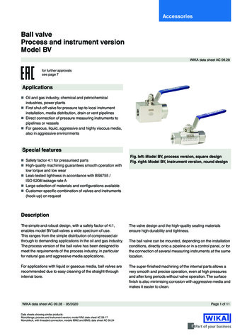
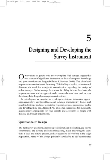
AccessoriesMonoflangeProcess and instrument versionModel IVMWIKA data sheet AC 09.17Applications Shut-off and venting of pressure measuring instruments Flange connection of instruments with threadedconnections to pipelines or vessels For aggressive liquids, gases and vapours, also inaggressive environments Oil and gas industry, chemical and petrochemicalindustries, power plants, primary metalsSpecial features Compact design with low number of potential leakagepoints reduces overall weight Threaded mounting of bonnets not wetted to avoid seizureand leaks Smooth valve actuation, even under high pressure, leadsto fault-free operation and long service life Metal valve seat with leak-tested tightness in accordancewith BS6755 / ISO 5208 leakage rate A Instrument version for “fugitive emissions” according toTA-Luft and ISO 15848-1Fig. left: Instrument versionFig. right: Process version with OS&Y bonnetDescriptionDue to its one-piece design, the model IVM monoflangecan withstand high overpressures. It ensures a robust andcompact mounting of the measuring instrument directly to theprocess flange. The use of metal and graphite seals allowsworking at high temperatures.In combination with pressure measuring instruments,diaphragm seals or level measuring instruments, the valvesare suitable for use in critical applications like refineries orsteam generation systems. The IVM can be used for “fugitiveemissions” in chemical applications or for processes withcritical gases. The bubble-tight leak-tested metal seat makesthese valves perfectly suitable for sour gases and natural gasprocessing or nitrogen production plants.The super-finished machining of the internal parts, such asspindle and spindle tip, allows a very smooth and preciseoperation, even at high pressures, and avoids leaks orseizure of the valve. The OS&Y bonnet has been specificallydeveloped in accordance with the highest internationalstandards for the direct mounting of IVM monoflanges onpipelines or vessels.WIKA offers the professional assembly of differentinstruments and valves into ready-to-install hook-upsolutions.WIKA data sheet AC 09.17 03/2019Data sheets showing similar products:Block-and-bleed valve, 2-valve manifold; models IV20 and IV21; see data sheet AC 09.19Valve manifold for differential pressure measuring instruments, models IV30, IV31, IV50 and IV51; see data sheet AC 09.23Page 1 of 10
SpecificationsMonoflange, model IVMStandards usedDesign ASME B16.5, pipe flanges and flange fittingsASME B16.34, valves - flanged, threaded and welding endASME B1.20.1, pipe threads, general purpose (inch)ASME B31.1, power pipingASME B31.3, process pipingISO 17292, metal ball valves for petroleum, petrochemical and allied industriesMSS SP-99, valves for measuring instrumentsTests API 598, valve inspection and testingBS EN ISO 10497, type testing in accordance with fire safety requirementsISO 5208, pressure testing of metallic valves with leakage rate AMSS SP-61, pressure testing of valvesDIN EN 12266-1, pressure tests, test procedures and acceptance criteria for industrial valvesMaterial requirements NACE MR0175 / ISO 15156, use in H₂S-containing environments in oil and gas production NORSOK M-630, specificaiton for use in pipelines (Norway)MarkingMSS SP-25, marking on valvesFunction(for functional diagram, seenext page) Block (shut off)Version Process version (with OS&Y bonnet on the process side) Instrument version (with standard bonnet on the process side)Process connection(see page 8 ff.) Flange ½" 2" / class 150 class 2500, following ASME B16.5 Flange DN 15 DN 25 / PN 16 PN 100, following EN 1092-1- 1 x bonnet for shutting off the process Block and bleed (shut off and vent)- 1 x bonnet for shutting off the process- 1 x standard bonnet for venting Double block and bleed (2 x shut off and 1 x vent)- 2 x bonnets for shutting off the process- 1 x standard bonnet for ventingSurface roughness Ra of the sealing faceFollowing ASME B16.5 RF: 3.2 . 6.3 μm [125 . 250 μin] (spiral surface) RJ: 1.6 μm [63 μin]Following EN 1092-1 Form B1: 3.2 . 6.3 μm [125 . 250 μin] Form B2: 0.8 . 3.2 μm [32 . 125 μin]1 x ½" NPT female, axial1 x ½" NPT female, swivel adapter, axial2 x ½" NPT female, 1 x radial and 1 x axial 1)2 x ½" NPT female, 1 x swivel adapter, radial and 1 x axial 1)Connecting flangeInstrument connection(see examples on page 7) Vent connection Without ¼ NPT female, plug screw is included in delivery, though not pre-fitted. ½ NPT female, plug screw is included in delivery, though not pre-fitted.1) Axial and/or radial instrument connection can be used. Optionally, one measuring instrument connection can be closed with the supplied plug screw.WIKA data sheet AC 09.17 03/2019Page 2 of 10
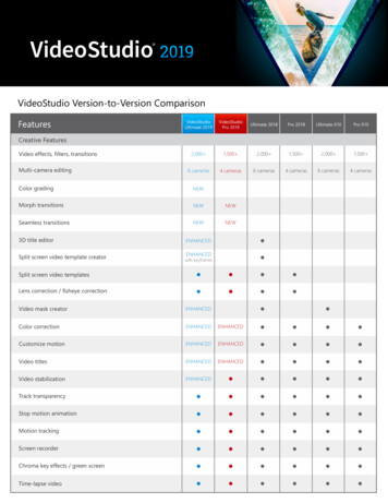
Functional diagramBlock (shut off)Colour codeBlock and bleed (shut off and vent)Double block and bleed(2 x shut off and 1 x vent)Blue: Shut offRed: VentMaterialsWetted partsFlangeMonoflangeSpindle tipSealing packing Stainless steel 316L (standard)Duplex F51 (1.4462)Super Duplex F55 (1.4501)Hastelloy C276 (2.4819)Monel 400 (2.4360)Steel A350 LF2 (1.0566), galvanised carbon steel per ISO/EN 2081 1) 2) PTFE Graphite RTFEReinforced PTFE, material for optional certificate „Emission protection in accordance with TA-Luft(VDI 2440) and ISO-15848-1Non-wetted partsGland packing, gland nut, yoke,valve spindle, seal bush, threadedbolt with nutStainless steel 316LHandle Stainless steel Stainless steel 316/316L1) Lacquered version on request2) Flange from steel A350 LF2 (1.0566), bonnet and spindle tip from stainless steel 316/316LWIKA data sheet AC 09.17 03/2019Page 3 of 10
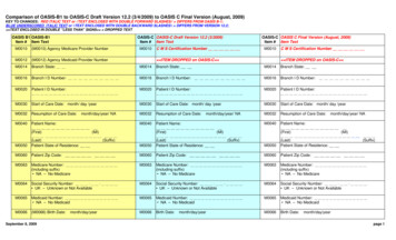
Bonnet versionsStandardOS&YT-bar handleT-bar handleYokeColoured dust capBlue dust capGland nutGland packingThreaded bolt with nutValve spindleValve spindleSeal bushSeal bushSealing packingSealing packingBonnet bodyBonnet bodySpindle tipSealing ringSealing ringSpecificationSpindle tipStandard bonnetStandards complied with ASME VIII div. 1 and MSS SP-99 TA-Luft (VDI 2440) and ISO-15848-1 (option)Dust cap colour codeBlue: Shut offRed: VentSpindle tipNon-rotating, low-wear, blow-out-safeValve bore size5 mm [0.197 in]Valve seatOS&Y bonnet ASME VIII div. 1 and ASME B31.1, ASME B31.3 API 607, ISO 10497, BS 6755-2Metal-to-metal, back seat designBonnet optionsAnti-tamper versionAnti-tamper version with padlockAnti-tamper key1)1) The anti-tamper key is not included in delivery of the anti-tamper version, but available as accessory.WIKA data sheet AC 09.17 03/2019Page 4 of 10
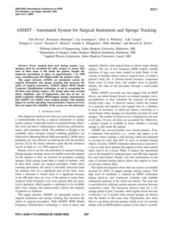
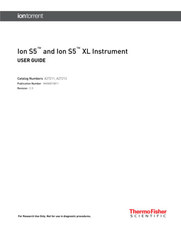
Pressure-temperature diagram700(10153)PTFE600(8702)GraphiteRTFE 1)Pressure in bar 0Temperature in C ( F)Material of thesealing packingPTFEGraphiteRTFE 1)Max. permissible operating pressure in barat temperature in CMax. permissible operating pressure in psiat temperature in F690 bar at 38 C10,000 psi at 100 F276 bar at 204 C4,000 psi at 400 F420 bar at 38 C6,000 psi at 100 F209 bar at 538 C3,030 psi at 1.000 F420 bar at 38 C6,000 psi at 100 F276 bar at 180 C4,000 psi at 356 F1) Reinforced PTFE, material for optional certificate „Emission protection in accordance with TA-Luft (VDI 2440) and ISO-15848-1The minimum design temperature is -54 C [-65 F].For continuously low operating temperatures -54 C [ -65 F] a special design is needed.WIKA data sheet AC 09.17 03/2019Page 5 of 10
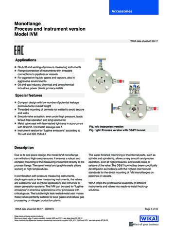
Installation examplesInstrument versionHorizontal flange arrangementProcess versionHorizontal flange arrangementVertical flange arrangementVertical flange arrangementInstrument monoflanges are, as shown, installed behind an initialshut-off device. Process monoflanges are designed with an OS&Ybonnet for the process-side shut-off. The broad design of thepassage geometries of the OS&Y bonnet prevents clogging throughparticle accumulation. With the use of process monoflanges, thepurchase of traditional shut-off devices can be saved.The monoflange assembly enables the integration of up to threebonnets with compact dimensions. Flange connections areadvantageous for frequent maintenance and service operations andfor applications with hazardous media.WIKA data sheet AC 09.17 03/2019Page 6 of 10
Examples for process connection and instrument connectionProcess and instrument connection: FlangeWIKA data sheet AC 09.17 03/2019Process connection: FlangeInstrument connection: Swivel adapter, axialPage 7 of 10
Model IVM, process version14325842.01Monoflange design from DN 2" Class 300 and higher14325848.01Block and bleed, up to DN 2" Class 15014325839.01Double block and bleed, up to DN 2" Class 15014325853.01BlockFlange connection per ASME B 16.5DNClassDimensions in mm [in]ABCØDE for RFE for RJF40 [1.57]½"150100 [3.94]96 [3.78]113 [4.45]88.9 [3.5]50.6 [2]-½"300/600103.2 [4.06]99.3 [3.91]116.8 [4.60]95.2 [3.75]55.4 [2.18]½"900/1500116 [4.57]112.3 [4.42]131.4 [5.17]120.6 [4.75]55.4 [2.18]½"2500121 [4.76]117 [4.61]138.5 [5.45]133.3 [5.25]¾"150105 [4.13]101 [3.98]118.8 [4.68]98.4 [3.87]¾"300/600115 [4.53]110.8 [4.36]129.6 [5.10]¾"900/1500121 [4.76]117 [4.61]¾"2500122 [4.80]118 [4.65]1"150109.8 [4.32]1"300/600118 [4.65]1"900/15001"25001 ½"1 ½"x 1) Weightkg [lb]40.7 [1.45]54.5 [2.15]40.8 [1.8]55.4 [2.18]41.3 [2.95]55.4 [2.18]55.4 [2.18]41.7 [3.71]50.6 [2]-40.9 [1.9]117.5 [4.62]55.4 [2.18]55.4 [2.18]41.3 [2.8]136.7 [5.38]130.2 [5.12]55.4 [2.18]55.4 [2.18]41.6 [3.5]142 [5.59]139.7 [5.5]55.4 [2.18]55.4 [2.18]41.9 [4.2]106 [4.17]124.2 [4.89]107.9 [4.25]50.6 [2]55.4 [2.18]41.1 [2.4]114 [4.49]133 [5.24]123.8 [4.87]55.4 [2.18]55.4 [2.18]41.5 [3.3]130.8 [5.15]127 [5]147 [5.79]149.2 [5.87]55.4 [2.18]55.4 [2.18]42.1 [4.7]135.6 [5.34]132 [5.20]152 [5.98]158.7 [6.25]55.4 [2.18]55.4 [2.18]42.5 [5.5]150119.5 [4.70]115.6 [4.55]135 [5.31]127 [5]50.6 [2]55.4 [2.18]42.4 [5.3]300/600134 [5.28]130 [5.12]150.2 [5.91]155.6 [6.12]55.4 [2.18]55.4 [2.18]42.4 [5.3]1 ½"900/1500146.5 [5.77]142.6 [5.61]163 [6.42]177.8 [7]55.4 [2.18]55.4 [2.18]43.2 [7.1]1 ½"2500158 [6.22]154 [6.06]174.7 [6.88]203.2 [8]55.4 [2.18]56.9 [2.24]45.4 [11.8]2"150132.5 [5.22]128.6 [5.06]148.7 [5.85]152.4 [6]50.6 [2]55.4 [2.18]42.4 [5.2]2"300/600138.9 [5.47]135 [5.31]155.5 [6.12]165.1 [6.5]55.4 [2.18]56.9 [2.24]82.8 [6.1]2"900/1500164.6 [6.48]161 [6.34]182 [7.17]215.9 [8.5]55.4 [2.18]56.9 [2.24]84.8 [10.5]2"2500174 [6.85]170.2 [6.70]191.5 [7.54]234.9 [9.25]66.2 [2.61]67.7 [2.67]87.1 [15.7]1) Number of screwsPlug screw for vent connection is included in delivery, though not pre-fitted.WIKA data sheet AC 09.17 03/2019Page 8 of 10
Model IVM, instrument version14325450.01Monoflange design from DN 2" Class 300 and higher14325434.01Block and bleed, up to DN 2" Class 15014325447.01Double block and bleed, up to DN 2" Class 15014325430.01BlockFlange connection per ASME B 16.5DNClassDimensions in mm [in]ABØDE for RFE for RJFx 1)Weightkg [lb]15099.9 [3.9]96 [3.7]88.9 [3.5]40.6 [1.6]-.30 [1.2]40.5 [1.15]½"300/600103.2 [4.1]99.3 [3.9]95.2 [3.75]45.3 [1.8]44.5 [1.7]30 [1.2]40.5 [1.2]½"900/1500116.3 [4.6]112.4 [4.4]120.6 [4.75]45.3 [1.8]45.3 [1.8]30 [1.2]41 [2.2]½"2500122.8 [4.8]118.9 [4.7]133.3 [5.25]45.4 [1.8]45.4 [1.8]30 [1.2]41.3 [2.9]¾"150104.9 [4.1]101 [3.9]98.4 [3.87]40.6 [1.6]-30 [1.2]40.7 [1.5]¾"300/600114.7 [4.5]110.8 [4.4]117.5 [4.62]45.4 [1.8]45.4 [1.8]30 [1.2]40.7 [1.5]¾"900/1500121.2 [4.8]117.3 [4.6]130.2 [5.12]45.4 [1.8]45.4 [1.8]30 [1.2]41.2 [2.7]¾"2500126 [4.9]122.1 [4.8]139.7 [5.5]47.1 [1.8]47.1 [1.8]31.7 [1.25]41.6 [3.5]1"150109.8 [4.3]105.9 [4.2]107.9 [4.25]40.6 [1.6]45.3 [1.8]30 [1.2]41 [2.1]1"300/600118 [4.6]114 [4.5]123.8 [4.87]45.4 [1.8]45.3 [1.8]30 [1.2]41.2 [2.6]1"900/1500130.9 [5.1]127 [5.0]149.2 [5.87]45.4 [1.8]45.4 [1.8]30 [1.2]41.6 [3.6]1"2500135.4 [5.3]131.5 [5.2]158.7 [6.25]50.4 [2.0]50.4 [2.0]35 [1.4]42.5 [5.5]1 ½"150119.6 [4.7]115.7 [4.6]127 [5]40.6 [1.6]45.4 [1.8]30 [1.2]41.4 [3]1 ½"300/600134 [5.3]130 [5.1]155.6 [6.12]40.6 [1.6]45.4 [1.8]30 [1.2]41.8 [4]1 ½"900/1500146.5 [5.8]142.6 [5.6]177.8 [7]47.2 [1.9]47.2 [1.9]31.8 [1.2]43.5 [7.7]1 ½"2500158.1 [6.2]154.2 [6.1]203.2 [8]60.1 [2.3]61.6 [2.4]44.7 [1.76]44.8 [10.6]2"150132.5 [5.2]128.6 [5.1]152.4 [6]40.6 [1.6]45.4 [1.8]30 [1.2]41.8 [3.9]2"300/600138.9 [5.5]135 [5.3]165.1 [6.5]45.4 [1.8]46.9 [1.85]30 [1.2]81.8 [4]2"900/1500164.6 [6.5]160.7 [6.3]215.9 [8.5]53.5 [2.1]55 [2.2]38.1 [1.5]84.7 [10.3]2"2500174 [6.85]170.1 [6.7]234.9 [9.25]66.2 [2.6]67.7 [2.7]50.8 [2.0]87.4 [16.3]½"1) Number of screwsPlug screw for vent connection is included in delivery, though not pre-fitted.WIKA data sheet AC 09.17 03/2019Page 9 of 10
ApprovalsLogoDescriptionCountry-CRNSafety (e.g. electr. safety, overpressure, .)CanadaEurasian Economic CommunityEAC (option)Machinery directiveManufacturer‘s information and certificatesLogo Description-PMI 1) test certificate (option)Valve body-Certificate for oxygen versions (option)- Oil and grease free for oxygen per ASTM G93 level C- Sealing packing 2) and lubricants in accordance with BAM requirements- Limits of the permissible operating ranges for pressure and temperature:420 bar at 60 C or 6,000 psi at 140 F90 bar at 200 C or 1,305 psi at 392 F-Emission protection in accordance with TA-Luft (VDI 2440) and ISO-15848-1 (option) 3)- Tightness class: AH- Endurance class: C01- Temperature class: -29 . 180 C [-20 . 356 F]-Type tested for fire safety in accordance with API 607, ISO 10497, BS 6755-2 4)1) Positive material identification2) PTFE or graphite3) Only for standard bonnet4) Only for OS&Y bonnetCertificates 3.1 inspection certificate per EN 10204- Material certificate for the valve body per NACE MR0103/MR0175- Confirmation of pressure tests per API 598 5) 3.1 inspection certificate per EN 10204 (option)- Material certificate for all wetted parts per NACE MR0103/MR0175- Confirmation of pressure tests per API 598 5)5) Shell test: 15 s test duration with 1.5 times the permissible working pressureSeat test: 15 s test duration with 1.1 tim
MSS SP-99, valves for measuring instruments Tests API 598, valve inspection and testing BS EN ISO 10497, type testing in accordance with fire safety requirements ISO 5208, pressure testing of metallic valves with leakage rate A MSS SP-61, pressure testing of valves DIN EN 12266-1, pressure tests, test procedures and acceptance criteria for industrial valves Material requirements NACE MR0175 .