Transcription
Hydraulic Cartridge SystemsProduct Selection Guideaerospaceclimate controlelectromechanicalfiltrationfluid & gas handlinghydraulicspneumaticsprocess controlsealing & shielding
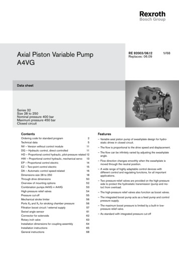
Presenting.We would like to take thisopportunity to welcome youto the new Hydraulic CartridgeSystems Division. This newProduct Selection Guiderepresents our publishedproduct offering. This Guide isintended to replace all previousHydraulic Cartridge Systems(HCS) catalogs. You will findmany changes to this catalogin content and format. Hereare a few highlights of whatyou will find:e Complete ProductOffering Including: Check Valves Shuttle Valves Load/Motor Controls Flow Controls Pressure Controls Logic Elements Directional Controls Manual Valves Solenoid Valves Proportional ValvesWe at the Hydraulic CartridgeSystems Division hope you findthis Guide useful and want tothank you for turning to ParkerHannifin for your integratedhydraulic needs.WARNING - USER RESPONSIBILITYFAILURE OR IMPROPER SELECTION OR IMPROPER USE OF THE PRODUCTS DESCRIBED HEREIN OR RELATED ITEMS CAN CAUSE DEATH,PERSONAL INJURY AND PROPERTY DAMAGE.This document and other information from Parker-Hannifin Corporation, its subsidiaries and authorized distributors provide product or system options for further investigationby users having technical expertise.The user, through its own analysis and testing, is solely responsible for making the final selection of the system and components and assuring that all performance, endurance,maintenance, safety and warning requirements of the application are met. The user must analyze all aspects of the application, follow applicable industry standards, and followthe information concerning the product in the current product catalog and in any other materials provided from Parker or its subsidiaries or authorized distributors.To the extent that Parker or its subsidiaries or authorized distributors provide component or system options based upon data or specifications provided by the user, the user isresponsible for determining that such data and specifications are suitable and sufficient for all applications and reasonably foreseeable uses of the components or systems.OFFER OF SALEThe items described in this document are hereby offered for sale by Parker-Hannifin Corporation, its subsidiaries or its authorized distributor. This offer and its accepteanceare governed by the provisions stated in the detailed "Offer of Sale" elsewhere in this document.
Threaded Cartridge Valves andIntegrated Hydraulic ProductsCheck ValvesCheckValvesCVShuttle ValvesShuttleValvesSHLoad and Motor Control ValvesLoad/MotorControlsLMFlow Control ValvesFlowControlsFCPressure Control ValvesPressureControlsPCLogic Element ValvesLogicElementsLEDirectional Control ValvesDirectionalControlsDCManual ValvesManualValvesMVSolenoid ValvesSolenoidValvesSVProportional ValvesProportionalValvesPVCoils and ElectronicsCoils &ElectronicsCEBodies and CavitiesBodies &CavitiesBCTDTechnical Data3Parker Hannifin CorporationHydraulic Cartridge SystemsTechnicalDataCatalog HY15-3501/US
NotesThreaded Cartridge Valves andIntegrated Hydraulic ProductsCatalog idValvesPVProportionalValvesCECoils &ElectronicsBCBodies &CavitiesTDTechnicalDataParker Hannifin CorporationHydraulic Cartridge Systems4
Catalog HY15-3501/USCheck ValvesCVH104P . C10-2 . Cartridge Check, Poppet Type. 2 to 1 Flow Path . 19/5 . 350/5000 .D06C2 . C16-2 . Cartridge Check, Poppet Type. 2 to 1 Flow Path . 500/132 . 420/6000 .PILOT OPERATED CHECKSCP084P . C08-3 . Single P.O. Check, Pilot on Port 1 . 19/5CPH104P . C10-3 . Single P.O. Check, Pilot on Port 1 . 30/8CPH124P . C12-3 . Single P.O. Check, Pilot on Port 1 . 75/20PP02SP . Single P.O. Check Package, Steel Body . 40/11PP04SP . Single P.O. Check Package, Steel Body . 135/36PP06SP . Single P.O. Check Package, Steel Body . 340/90. 207/3000 . 350/5000 . 350/5000 . 420/6000* . 420/6000* . 420/6000* .D4A020 . 53-1 . Single P.O. Check, Pilot on Port 3 . 30/8D4A040 . 68-1 . Single P.O. Check, Pilot on Port 3 . 60/16D2K1 . T11A . Single P.O. Check, Pilot on Port 3 . 70/19D3B125 . 3C . Single P.O. Check, Pilot on Port 3 . 150/40. 420/6000 . 420/6000 . 350/5000 . 420/6000 .CPC101P . C10-3 . Pilot to Close Check, Pilot on Port 3 . 20/5 . 420/6000 .CheckValvesSHShuttleValves. 420/6000 . 420/6000 . 420/6000 . 420/6000 . 350/5000 . 350/5000 . 420/6000 . 350/5000 . 420/6000 . 350/5000 . 350/5000 .CVLMLoad/MotorControlsSTANDARD CHECKSD1A060 . 2U . Check Valve Insert, Ball Type . 145/38D1B125 . 2C . Check Valve Insert, Ball Type . 500/132D0WB2 . CAV0W-2 . Cartridge Check, Ball Type . 3.5/0.9D02B2 . C08-2 . Cartridge Check, Ball Type . 45/12CVH081P . C08-2 . Cartridge Check, Poppet Type . 38/10CVH103P . C10-2 . Cartridge Check, Poppet Type . 60/16D04B2 . C10-2 . Cartridge Check, Ball Type . 160/42CVH121P . C12-2 . Cartridge Check, Poppet Type . 121/32D06B2P . C16-2 . Cartridge Check, Poppet Type . 280/74CVH161P . C16-2 . Cartridge Check, Poppet Type . 226/60CVH201P . C20-2 . Cartridge Check, Poppet Type . rectionalControlsSERIESMVManualValvesContentsCHECK WITH RELIEFD04F2 . C10-2 . Check With Thermal Relief,. Relieving Port 2 to 1 . 130/40 . 420/6000 .PVProportionalValves. 207/3000 . 420/6000* . 420/6000* . 420/6000* .CECoils &ElectronicsDUAL PILOT OPERATED CHECKSCPD084P . C08-4 . Dual P.O. Check Cartridge . 19/5PP02DP . Dual P.O. Check Package, Steel Body . 40/11PP04DP . Dual P.O. Check Package, Steel Body . 135/36PP06DP . Dual P.O. Check Package, Steel Body . 340/90SolenoidValvesSVBodies &CavitiesBC*Rated to 207 Bar/3000 PSI with Aluminum Body.5Parker Hannifin CorporationHydraulic Cartridge SystemsTechnicalDataTD
Catalog HY15-3501/USTechnical TipsCheck his technical tips section is designed to help familiarize you with the Parker line of Check Valves. In this sectionwe present the products that are new to this catalog as well as some design features of our checks valves. Inaddition, we present common options available to help you in selecting products for your application.Finally we give a brief synopsis of the operation and applications of the various product offered in this section.NEW PRODUCTS:Load/MotorControlsThere are several new additions and product improvements to our Check Valve product line.Here are just some of the general design features and advantagesto the “Winner’s Circle” check valve.FCFlowControlsDual Sense PathsThe dual sense paths reducethe pressure drop variations.Spherical PoppetsThe spherical design allows for amore consistent seating regardlessof poppet alignment resulting inlower leakage.PCPressureControlsLELogicElementsYellow Zinc CoatingSteel adapters arecoated with yellow zincdi-chromate for protectionfrom salt spray.Hardened SeatSeats are hardened to reducethe degredation of the seatingarea and increase life.DCDirectionalControlsCrimp DesignFold over crimp provides secureholding and eliminates the needfor adhesive.MV“D”-RingStandard 4301 Polyurethane sealeliminates the need for backup ringsproviding easier manifold installation.(For more information see theTechnical Data lValvesCECoils &ElectronicsBCBodies &CavitiesTDCOMMON OPTIONS:Since check valves and shuttles are fairly simplecomponents, there are very few options. Here are thestandard options you will find.Seals: The Winner’s Circle products feature astandard 4301 Polyurethane “D”-Ring. The “D”-Ringeliminates the need for backup rings. The majority ofthe products are available in Nitrile or FluorocarbonSeals. You should match the seal compatibility to thetemperature and fluid being used in your application.Pilot Piston Seal: On the pilot piston style pilotoperated check valves, Parker offers the option toplace a seal on the piston to reduce the leakageacross the piston. Note: Sealing the pilot piston doesnot decrease the leakage across the poppet. In otherwords, if you are trying to reduce the leakage from theactuator port, sealing the piston will not help. Whilemost applications do not require a seal on the piston, itcan be advantageous in applications with very smallpump flows where the lost fluid would have a highimpact on actuator speed.TechnicalDataCrack Pressure: Parker offers a number of standardcrack pressure options for each valve. Check themodel code pages for these options. The crack pressure is defined as the minimum amount of pressurethat is needed to unseat the poppet. In pilot operatedcheck applications, you may want to go with a slightlyhigher cracking pressure to keep the piston weight,friction, and drag from accidently unseating the poppet.6Parker Hannifin CorporationHydraulic Cartridge Systems
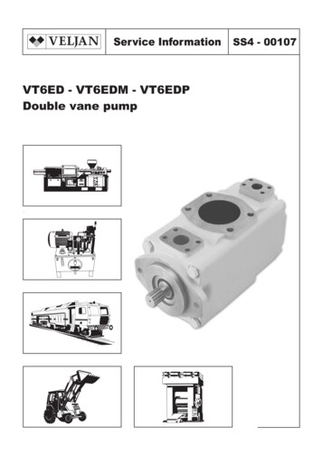
Catalog HY15-3501/USTechnical TipsCheck ValvesCV(2)SH(1)ShuttleValvesCheck Valve - Poppet TypeCheck valves are poppet style elements (1)(2)that allow free flow in one direction whilepreventing flow in the reverse direction.They can be used to isolate portions ofa hydraulic circuit or to provide a free flow path around a restrictive valve.CheckValvesPRODUCT TYPES / APPLICATIONSLoad/MotorControlsLMOPERATION - Pressure on the inlet (port 1) of the check valve creates a force against the poppet, pushing itoff its seat and permitting free flow to port 2. Reverse flow through the check is blocked by the poppet.Check Valve - Ball TypeBall type check valves are check valves (1)that use a hardened steel ball to sealagainst the valve seat as opposed to apoppet. They are simple in their designand provide low leakage over the life of the system.FlowControlsFC(2)LELogicElementsOPERATION - Pressure on the inlet (port 1) of the check valve creates a force on the steel ball pushing it off ofit’s seat and permitting free flow to port 2. Reverse flow through the check is blocked by the steel ball on the noidValvesOPERATION - Pressure on the inlet (port 2) of the check valve creates a force against the poppet, pushing itoff its seat and permitting free flow to port 1. Reverse flow through the check is blocked by the poppet.DCManualValvesSide to Nose Check Valve(2)Side to nose check valves are a special (2)(1)type of check valve where the free flow(1)path is from the side of the cartridgevalve to the nose. They functionally arethe same as the standard check valve. Side to nose check valves areoccasionally used by manifold designers to simply the flow path design of their blocks.ProportionalValvesPVCoils &ElectronicsCEBodies &CavitiesBCTechnicalDataTD7Parker Hannifin CorporationHydraulic Cartridge Systems
Catalog HY15-3501/USTechnical TipsCheck sDCPilot Operated Check Valve(1)Pilot operated check valves (also referred (3)(2)to as P.O. check valves), are checkvalves which can be opened by an(1)external pilot pressure. Thus, P.O.checks, block flow in one direction, likestandard check valves, but can be released once an adequate pilotpressure is applied. Free flow is allowed in the reverse direction. P.O.checks are often used to positively lock a dual acting cylinder. Thereare two types of pilot operated check valves; threaded cartridge styleand pilot piston style. These valves work best when used in conjunctionwith a control valve that vents the valve ports to tank when centered.DirectionalControlsOPERATION - In the absence of adequate pilot pressure, the poppetremains seated preventing flow from the actuator port (port 3) to thevalve port (port 2). Once adequate pilot pressure is applied at the pilotport (port 1), the internal pilot piston unseats the check poppet permittingflow from port 3 to port 2. The amount of pressure needed at port 1 tounseat the check valve is determined by the pilot ratio of the pilot pistonto the poppet seat diameter. If you have a pilot operated check valvewith a 3:1 ratio pilot piston, then you would need a pilot pressure atport 1 that is 1/3 of the pressure being checked at port 3 plusthe spring. For example, if you had 3000 psi on port 3 and a5 psi spring and a 3:1 pilot ratio, it would take 1002 psi[(3000 psi 5 psi) / 3)] to release the check valve.Free flow is permitted from the valve port (port 2) to thecylinder port (port 3).Cartridge Style P.O. Check Valve(2)(3)Single Pilot Piston Style P.O. Check ValveDual Pilot Piston Style P.O. Check alvesCECoils &ElectronicsBC(1)(2)Check Valve With Thermal ReliefThe check valve with thermal reliefperforms the same function as astandard check valve. It allows free flowin one direction. In the opposite direction,it performs as a normal check valvepreventing flow, while also venting excess pressure caused by thethermal expansion of fluid. This type of valve can be used with anexternal pilot piston to provide a pilot operated valve that will vent trappedpressure due to thermal expansion. These valves work best when used inconjunction with a control valve that vents the valve ports to tank when centered.Bodies &CavitiesOPERATION - The check valve is a guided poppet design. As the pressure on the inletexceeds the spring rate, the poppet is pushed off of its seat allowing flow to pass. Once thepressure on the inlet side drops below the spring force, the spring then pushes the poppetback on its seat blocking flow from the outlet to the inlet of the check valve. If the pressure onthe outlet side of the check valve (when it is in a load holding function) rises (through thermalexpansion), the direct acting relief will vent the excess pressure caused by the thermalexpansion to the inlet side of the check.TDTechnicalData8Parker Hannifin CorporationHydraulic Cartridge Systems
Catalog HY15-3501/USTechnical TipsCheck ilot to Close CheckPilot to close check valves are unique2 way valves that act as a checkvalve, allowing free flow in onedirection and blocking flow from theopposite direction. When an externalpilot pressure is applied, flow isblocked from both directions.(1)Load/MotorControlsLMOPERATION - In the absence of adequate pilot pressure,the valve functions as a simple check valve, allowing freeflow from port 1 to port 2. When adequate pilot pressure atport 3 is applied, the pilot piston holds the poppet closed,blocking flow in both CFlowControlsThese products are ideal for regeneration circuits.See sample diagram lvesMVSolenoidValvesSVProportionalValvesPVCoils &ElectronicsCEBodies &CavitiesBCTechnicalDataTD9Parker Hannifin CorporationHydraulic Cartridge Systems
Catalog HY15-3501/USCheck ValvesTechnical alvesPVProportionalValvesCECoils &ElectronicsBCBodies &CavitiesTDTechnicalDataParker Hannifin CorporationHydraulic Cartridge Systems10
Catalog HY15-3501/USShuttle SWA3 . SW-3 . Ball Insert Type . 9.5/2.5 . 420/6000 .K2A005 . 3Z . Poppet Insert Type . 38/10 . 350/5000 .CS041B . C04-3 . Cartridge Shuttle . 3.8/1.0 . 207/3000 .K02A3 . C08-3 . Cartridge Shuttle . 50/13 . 420/6000 .CSH101B . C10-3 . Cartridge Shuttle . 38/10 . 350/5000 .CVCheckValvesSERIESSHShuttleValvesContentsASH-04 . In-Line Shuttle,-4 Male JIC . 11/3 . 207/3000 .ASH-06 . In-Line Shuttle,-6T . 22/6 . 207/3000 .Load/MotorControlsLMFCFlowControlsK04B3 . C10-3 . Spool Type Shuttle . 90/24 . 420/6000 .PCPressureControlsK04D3 . C10-3 . Spool Type Shuttle . 90/24 . 420/6000 .LogicElementsLEK04C3 . C10-4 . Spool Type, Spring Centered,. All Ports Closed . 100/26 . 420/6000 .K3A125 . 3J . Spool Type, Spring Centered,. All Ports Closed . 175/46 . 350/5000 .K04F3 . C10-4 . Spool Type, Spring Centered,. All Ports Open . 100/26 . 420/6000 .DirectionalControlsDCK04G3 . C10-4 . Spool Type Shuttle, Inverse . 50/13 . 350/5000 VCoils &ElectronicsCEBodies &CavitiesBCTechnicalDataTD11Parker Hannifin CorporationHydraulic Cartridge Systems
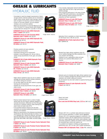
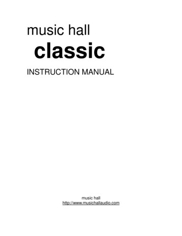
Catalog HY15-3501/USTechnical TipsShuttle oad/MotorControlsFCShuttle valves accept flow from two different sources and divert the highest pressure to a single outlet port.Shuttle valves are commonly used in Load Sensing circuits as well as Brake circuits. Parker offers manydifferent types of shuttles, including ball type, poppet type, spool type. There are a number of configurationsavailable such as cartridge type, insert type, and an in-line version.(2)OutletFlowControls(2)Ball Type - Cartridge StyleThe valve consists of a steel ball that(3)(1)can seal against one of two adjacentseats, providing a path from the highestpressure signal to another function.When one inlet port is pressurized, theball or poppet is forced against the opposite seat,blocking that inlet and providing a flow path to the outlet port.(3)Inlet(1)InletPCPressureControlsLEPoppet Type - Insert StyleThis shuttle performs the samefunction, but allows for higher flowrates due to poppet design.(2) ntrolsMVIn-Line TypeThis shuttle variant performs the samefunction in a self-contained body. It canbe mounted anywhere on the VSolenoidValvesSpool Type - Centered or Spring OffsetThe spool type shuttle allows for higher flow rates. These are 2 position valves.PVProportionalValvesCECoils &ElectronicsBC(3)(3)(1)(1)(2)(2)(2) Out(2) Out(3) In(3) In(1)In(1)InBodies &CavitiesTDTechnicalData12Parker Hannifin CorporationHydraulic Cartridge Systems
Catalog HY15-3501/USTechnical TipsShuttle Valves(3)(1)(3)SHShuttleValves3 Way 2 Position Spool type shuttles are designed to direct flow in such a way as to allow higher pressuresignals to open the lower pressure port and connect it to the common outlet port. These spring centered valveswill shift when pressure at either end of the spool exceed the spring setting. These are typically used intransmission hot oil shuttle circuits.CheckValvesCV(1)(2)(2)(3) In(1) In(2) Out(3) ProportionalValvesPVCoils &ElectronicsCEBCBodies &Cavities(2) OutTDTechnicalData(1) InLoad/MotorControlsLM13Parker Hannifin CorporationHydraulic Cartridge Systems
Catalog HY15-3501/USShuttle ValvesTechnical alvesPVProportionalValvesCECoils &ElectronicsBCBodies &CavitiesTDTechnicalDataParker Hannifin CorporationHydraulic Cartridge Systems14
Catalog HY15-3501/USLoad and Motor Control R/PSISHE2*020 . 53-1 . Load Control Cartridge Valve . 20/5.3 . 420/6000 .LME2*1S . T11-A . Load Control Cartridge Valve . 60/16 . 350/5000 .E2*1R . T11-A . Load Control Cartridge Valve . 60/16 . 350/5000 .E2*060 . 3C . Load Control Cartridge Valve . 120/32 . 350/5000 .E2*125 . 3M . Load Control Cartridge Valve . 200/53 . 350/5000 .FCFlowControlsE2*1 . T11-A . Load Control Cartridge Valve . 60/16 . 350/5000 .PCPressureControlsE2*040 . 68-1 . Load Control Cartridge Valve . 60/16 . 350/5000 .Load/MotorControlsMHC-010-S*** CDD-1010 . Load Control Cartridge Valve . 37/10 . 350/5000 .MHC-022-S*** CDD-1036 . Load Control Cartridge Valve . 94/25 . 350/5000 .ShuttleValvesSTANDARD PILOT ASSISTEDCB101 . C10-3 . Load Control Cartridge Valve . 45/12 . 380/5500 .CVCheckValvesContentsE6*1 . T11-A . Load Control Cartridge Valve . 60/16 . 350/5000 .DCDirectionalControlsINDEPENDENT OF BACK-PRESSURE, VENTED TO ATMOSPHEREE6B020 . 53-1 . Load Control Cartridge Valve, 4.5:1 Ratio . 20/5.3 . 350/5000 .E6K020 . 53-1 . Load Control Cartridge Valve, 15:1 Ratio . 20/5.3 . 350/5000 .LogicElementsLEE2*300 . 3K Flange . 350/90 . 350/5000 .MHC-010-V*** CDD-1010 . Load Control Cartridge Valve . 37/10 . 350/5000 .MHC-022-V*** CDD-1036 . Load Control Cartridge Valve . 94/25 . 350/5000 .SVSolenoidValvesE6A060*409 . 3C . Load Control Cartridge Valve, 3:1 Ratio . 180/48 . 350/5000 .E6B060*409 . 3C . Load Control Cartridge Valve, 3:1 Ratio . 180/48 . 350/5000 .ManualValvesMVE6B040 . 3C . Load Control Cartridge Valve, 3:1 Ratio . 60/16 . 350/5000 .CECoils &ElectronicsINDEPENDENT OF BACK-PRESSURE, VENTED TO DRAIN ON PORT 4E9*1 . T21A . Load Control Cartridge Valve . 60/16 . 350/5000 .ProportionalValvesPVBodies &CavitiesBCTechnicalDataTD15Parker Hannifin CorporationHydraulic Cartridge Systems
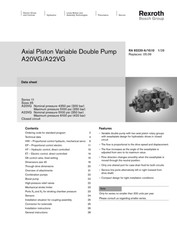
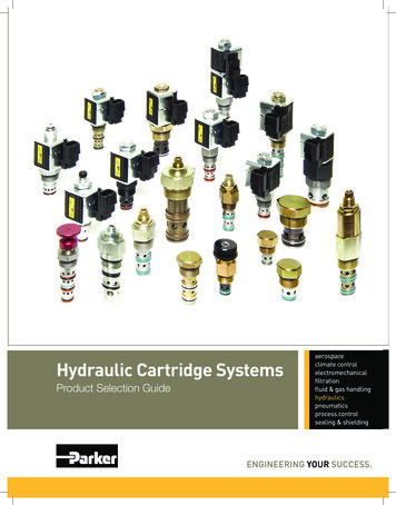
Catalog HY15-3501/USTechnical TipsLoad and Motor Control SolenoidValvesPVProportionalValvesCECoils &ElectronicsBCBodies &CavitiesTDCounterbalance valves are one of the most misunderstood products in the hydraulic industry. Many people tend tocomplicate the task of selecting a counterbalance valve and as such avoid opportunities. The goal of this TechnicalTips Section is to hopefully eliminate some of this confusion and help you chose the correct valve for your application. It is only a guide! It is not meant to be your only method of input, nor is it meant to replace good hydrauliccommon sense and reasoning.ApplicationHelp Protect Against Hose Failures – Since thefluid must be pushed through aLOADrestriction, hose failures resultin a controlled movement ofthe actuator and nota runaway load.DO I NEED A COUNTERBALANCE VALVE?A counterbalance is generally used for one or more ofthe following purposes:Control an Overrunning Load – It restricts the flowfrom an actuator, thus forcing the load to be pushedthrough the restriction and providing control of thepotential runaway load. This also helps in the prevention of cavitation.Bias SpringProvidesProtectionForceRequiredControl in Critical Metering Applications – Theoutward restriction also helps to gain control of systems with varying loads and speeds.When HoseBreaks LoadMust Be Pushed DownHolding a Load – Much like a pilot operated checkvalve, a load is held in one direction until the appropriate pilot pressure is available unseat the check andpass fluid.NOTE: Counterbalance Valves are only needed if the application calls for varying loads or varying speeds. If the loadand speed are fixed, flow control valves and pilot operatedcheck valves may be substituted at generally a lower cost.OperationAn understanding of the general operation of a counterbalance valve is required before proceeding furtherinto valve selection.ValvePortThe counterbalance valve is a pressure control deviceand functions as follows: Pressure is developed at theWork Port of the holding valve when the actuator ispressurized. This pressure acts on the differential area,and the force generated is counteracted by the biasspring. When there is sufficient pressure present toovercome the spring setting, the poppet begins to shift,allowing fluid to pass through the valve port to tank viathe control valve.DifferentialAreaPilotPortWorkPortBias SpringBy-PassCheckTechnicalDataAn added feature of the counterbalance valve is itsbuilt-in thermal relief characteristic. A temperature risecan cause thermal expansion of the hydraulic fluidtrapped between the actuator and the counterbalancevalve’s poppet. As the pressure increases and reachesthe bias spring setting, the poppet unseats and a fewdrops of oil are allowed to escape through the valveport of the counterbalance valve. This relieves thethermal expansion of oil, allowing the counterbalancevalve to continue holding the load in the same position.When the flow is reversed to the actuator, then pressure unseats the built-in bypass check portion of thecounterbalance valve allowing flow to pass from thevalve port to the work port. When no pressure isapplied to either port of the counterbalance valve, theload is held in place.To assist in the shifting of the poppet, an externalpressure source (generally the opposite side of theactuator) is connected to the pilot port of the counterbalance valve. This pressure is applied to the pilot areaand assists the differential area in opening the valve.The pilot assist reduces load pressure required toopen the valve, and allows for a reduction in thehorsepower required to
Hydraulic Cartridge Systems Check Valves Shuttle Valves Load/Motor Controls Flow Controls Pressure Controls Logic Elements Directional Controls Manual Valves Solenoid Valves Proportional Valves Coils & Electronics Bodies & Cavities Technical Data SH CV LM FC P