Transcription
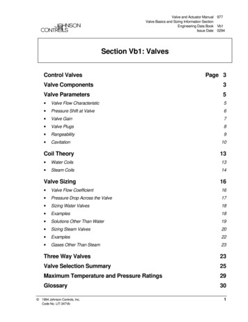
Valve and Actuator Manual 977Valve Basics and Sizing Information SectionEngineering Data Book Vb1Issue Date 0294Section Vb1: ValvesControl ValvesPage 3Valve Components3Valve Parameters5 Valve Flow Characteristic5 Pressure Shift at Valve6 Valve Gain7 Valve Plugs8 Rangeability9 CavitationCoil Theory1013 Water Coils13 Steam Coils14Valve Sizing16 Valve Flow Coefficient16 Pressure Drop Across the Valve17 Sizing Water Valves18 Examples18 Solutions Other Than Water19 Sizing Steam Valves20 Examples22 Gases Other Than Steam23Three Way Valves23Valve Selection Summary25Maximum Temperature and Pressure Ratings29Glossary30 1994 Johnson Controls, Inc.Code No. LIT-347Vb1
2 Vb1 Engineering Data Book
ValvesControl ValvesThe valve is a controlled device that regulates the flow of a liquid or gas ina system. This regulation is accomplished by the varying resistance thatthe valve introduces into the system as the valve is stroked. As the valvemodulates to the closed position the system pressure drop shifts to thevalve and reduces the flow in the system.The valve is very important to the operation of the system. Without aproperly sized valve the system will never operate at an efficient level.For valves that are oversized the result is poor controllability that maycause the system to hunt or cycle. Undersizing a valve will require alarger pressure drop across the valve to maintain adequate flow and maynot provide required capacity. This results in the pump working harderand leaves the valve susceptible to the effects of cavitation.ValveComponentsJohnson Controls currently manufactures three different styles of globevalve. They are the VT series valve, the Cage Trim style valve, and theIron Body Flange valve. The normally open versions of these valves areshown in Figures 1, 2, and 3. For information on butterfly valves consultthe Engineering Data Book Section Vb2: Butterfly Valves.Vb1 Engineering Data Book3
All globe style valves contain the same four basic sections; (1) Body, (2)Trim, (3) Bonnet, and (4) Actuator. The Body contains the orifice and isthe main housing through which the controlled fluid flows. The Trim isthe part of the valve excluding the body that comes in contact with thefluid. It is composed of the valve seat, plug, disc and disc holder, andstem. The Bonnet is an assembly that provides a mounting for theactuator and a guide through which the stem must pass. It is composed ofthe centerpiece, packing, packing guide, and packing nut. The packingprovides a seal between the stem and bonnet to prevent leakage. Thestandard packing available on the current valves is the EPDM (EthylenePropylene Diene Monomer) Ring Pack as shown in Figure 4. Many of thediscontinued JCI valves used a Teflon or graphite packing.The Actuator consists of either pneumatic or electric means to provide theforce to stroke the valve. Consult Section Va: Valve Actuator in theEngineering Data Book for further discussion.4 Vb1 Engineering Data Book
ValveParametersValve FlowCharacteristicThe factor that is most useful in selecting a valve type for a givenapplication is the flow characteristic. This characteristic is the relationshipthat exists between the flow rate through the valve and the valve stemtravel as the latter is varied from zero to 100 percent. Different valveshave different flow characteristics, depending primarily on internalconstruction. This flow relationship is usually shown in the form of agraph as in Figure 7. The characteristic that is usually graphed is theInherent Flow Characteristic that is found under laboratory conditionswith constant pressure drop across the valve. The inherent equalpercentage characteristic can be described by the following equation:Where: Q Flow rate (GPM)x Valve Position (in.)T Maximum Valve Travel (in.)Qm Maximum Flow rate (GPM)R Valve Rangeability (see Table II)These inherent flow characteristics are valuable for specifying a type ofvalve to be supplied by a manufacturer, but they do not reflect the actualperformance of the valve once installed within a system. The pressuredrop across the valve in the system is not constant; it varies with flow andother changes in the system. As the valve closes the pressure drop shiftsto the valve and away from the other system components. This has asignificant impact on the actual installed valve flow characteristic. Thedeviation from the inherent flow characteristic is a function of a propertycalled Valve Authority. It is defined as the ratio of the full flow valvepressure drop to the system pressure drop (including the valve).N Pvalve Psystemwhere: N Valve AuthorityThe actual characteristic when installed is known as the InstalledFlow Characteristic. The installed flow characteristic can bedescribed by the following equation which is a function of valveauthority and the inherent valve flow characteristic.Vb1 Engineering Data Book5
Pressure Shift atValveThis change in pressure drop across the valve can be attributed to twobasic causes. 1) the pump characteristic, which results in an increase inpump head as the flow is reduced and 2) the reduction in line losses as theflow is reduced, causing more and more of the pump head to appear acrossthe valve.The amount that the pump head will increase with a decrease in systemflow will depend upon the operating characteristics of the pump. A pumpwith a steep characteristic will produce a considerable increase in pressurehead as the system resistance is increased. However, a flat characteristicpump will produce a relatively constant, high pressure head for any systemflow. The relatively constant pressure would be preferable from a controlstandpoint but the advantages and disadvantages of the many varieties ofpumps are beyond the scope of this article.This point where the system curve crosses the pump characteristic curveshows the operating conditions (flow and head) that will exist for thisparticular pump for a given system resistance (see Figure 5a). The systemresistance is the combination of the pressure drop across the control valveand the other system components (coils, piping, balancing valves, etc.)pressure drop. As the valve is closed on a system in full flow, theresistance to the system flow that the valve provides (valve pressure drop)will increase by shifting from point A towards point B (See Figure 5b).This increasing resistance will use more of the head in the system, as wellas decrease system flow. The decrease in system flow will result in adecrease in pressure drop across every other component (coils, piping,balancing valves, etc.) and leave additional pressure drop for the controlvalve. This is because the resistance of the components is proportional tothe square root of the flow through them.6 Vb1 Engineering Data Book
The effect of these system variables can be minimized by keeping therelative change in valve pressure drop as small as possible. Because thetotal pump head will appear across the valve when it is closed, the bestway to keep the relative change as small as possible is to size the valve foras large a pressure drop as is permissible for the system. The largerpercentage this initial pressure drop is of the total pump head, the smallerthe relative change in pressure will be and the closer the valve installedflow characteristic will resemble its inherent flow characteristic.The desired result is to match a particular valve to a certain system. Thiscould involve a very detailed analysis of the control loop. However, witha basic knowledge of valves and a few generalizations the process can begreatly simplified.Valve GainValve gain is the incremental change in flow rate produced by anincremental change in plug position. This gain is a function of valve sizeand type, plug configuration and system operating conditions. The gain atany point in the stroke of a valve is equal to the slope of the valve flowcharacteristic curve at that point.Vb1 Engineering Data Book7
Valve PlugsThe shape of the valve plug determines the flow characteristic of thevalve. (See Figure 7) Matching this plug flow characteristic to a particularcontrol loop required that valve gain change in such a way as tocompensate for the gain changes of the other elements (coil, balancingvalve, piping, etc.) in the control loop. The valve gain is equal to the slopeof the flow characteristic and is of primary significance in establishing thecompatibility of the plug with the process. This will be shown graphicallywhen valve and coil combinations are considered.The most common types of plugs are the equal percentage, linear, andquick opening plug. Typically JCI offers the equal percentagecharacteristic. The idealized flow characteristics for these are shown inFigure 8.8 Vb1 Engineering Data Book
The equal percentage valve plug produces the same percentage change inflow per fixed increment of valve stroke at any location on itscharacteristic curve. For example, if 30% stem lift produces 5 gpm and alift increase of 10% to 40% produces 8 gpm or a 60% increase over theprevious 5 gpm then a further stroke of 10% now produces a 60% increaseover the previous 8 gpm for a total flow of 12.8 gpm. (see Table I below.)The flow through a linear valve plug varies directly with the position ofthe valve stem. This type of valve plug is normally utilized in processcontrol applications. They can be useful where it is desirable to controlmass flow rates into and out of a process such as liquid level control.A quick opening valve plug produces a large increase in flow for a smallinitial change in stem travel. Near maximum flow is reached at arelatively low percentage of maximum stem lift. Quick opening plugs arenormally utilized in two position applications but may be used in somelinear valve applications. This is possible because of its initial linearcharacteristic at a low percentage of stem travel. The slope of this linearregion is very steep which produces a higher initial gain than the linearplug but also increases the potential instability of the control valve.RangeabilityAnother valve parameter which can be considered at this point israngeability. Rangeability is defined as the ratio between maximum andminimum controllable flow through the valve. Large values forrangeability are desirable because it will allow for control across a largerportion of the valve stroke.(Maximum Flow)Rangeability ----------------------------------(Minimum Controllable Flow)Vb1 Engineering Data Book9
The rangeability for the current JCI valves are listed below in Table II.All valves have some amount of uncontrollable flow. This occurs whenthe plug is initially lifted off the seat and is due to the matching tolerancesbetween the plug and seat. Valves with high rangeabilities will benefitfrom lower uncontrollable flow rates for a given size valve plug. Thisuncontrollable flow rate can be approximated as shown in the followingexample.ExampleDetermine the uncontrollable flow rate through a 6 in. globe valve whereCv equals 350 and rangeability equals 10.4:1. Assume the full flow (wideopen) differential pressure across the valve equals 5 psig.It should be noted that in reality the pressure drop across a control valvewill normally rise due to pressure shifts within the hydronic system.These effects were not considered in the example. The pressure shifts arediscussed in Engineering Report H110 and H112. The net effect of thepressure shifts is to increase the uncontrollable flow rate.CavitationCavitation is a two-stage phenomenon which can greatly shorten the life ofthe valve trim in a control valve. Whenever a given quantity of liquidpasses through a restricted area such as an orifice or a valve port, thevelocity of the fluid increases. As the velocity increases, the staticpressure decreases. If this velocity continues to increase, the pressure atthe orifice will decrease below the vapor pressure of the liquid and vaporbubbles will form in the liquid. This is the first stage of cavitation.(See Figure 9)10 Vb1 Engineering Data Book
As the liquid moves downstream, the velocity decreases with a resultantincrease in pressure. If the downstream pressure is maintained above thevapor pressure of the liquid, the voids or cavities will collapse or implode.This is the second stage of cavitation. (See Figure 9)The second stage of cavitation is detrimental to valve. Because of thetremendous pressures created by these implosions (sometimes as high as100,000 psi), tiny shock waves are generated in the liquid. If these shockwaves strike the solid portions of the valve they act as hammer blows onthese surfaces. Repeated implosions on a minute surface will eventuallycause fatigue of the metal surface and chip a portion of this surface off.Tests show that only those implosions close to the solid surfaces of a valveact on the valve in this manner.Low degrees of cavitation are tolerable in a control valve. Minimumdamage to the valve trim and little variation in flow occur at these levels.However, there is a point where the increasing cavitation becomes verydetrimental to the valve trim and possibly even the valve body. It is at thispoint that the cavitation is beginning to choke the flow through the valveresulting in the flow rate staying the same regardless of increases inpressure drop.Vb1 Engineering Data Book11
The point at which cavitation becomes damaging can be expressed by thefollowing: Pallowable KM * (P1-Pv)KM Valve Recovery CoefficientP1 Absolute Inlet Pressure (psia) Pallowable Maximum Allowable Pressure Drop (psi)Pv Absolute Vapor Pressure (psia)The Valve Recovery Coefficient differs among various types and sizes ofvalves. The following values of KM are recommended for JohnsonControls globe valves:0.70.51/2 to 2 inch - Brass Body2-1/2 to 6 inch - Cast Iron BodyPv is based on temperature and can be found in Table III below or in anysteam tables book.The following is an example of calculating the maximum allowablepressure drop Pallowable.Given: 1 in
Sizing Steam Valves 20 Examples 22 Gases Other Than Steam 23 Three Way Valves 23 Valve Selection Summary 25 Maximum Temperature and Pressure Ratings 29 Glossary 30 Section Vb1: Valves. 2 Vb1 Engineering Data Book. Vb1 Engineering Data Book 3 Valves The valve is a controlled device that regulates the flow of a liquid or gas in a system. This regulation is accomplished by the