Transcription
ENReference ManualSolaira MalibuPost Kit with Alpha H1 HeatersMAL45240-CMAL60240-CC208V - 3375W / 240V - 4500W208V - 4500W / 240V - 6000W(3 1125 / 1500W)(3 1500 / 2000W) COLOR CODESHORTWAVE INFRARED HEATERS WITH POST & INCOMING TERMINAL BOX KITFOR: INDOOR USE - COMMERCIAL AND INDUSTRIAL ONLYOUTDOOR USE - RESIDENTIAL, COMMERCIAL AND INDUSTRIALFOR USE IN NON-HAZARDOUS AREAS ONLYPost and weatherproof terminal box rain tested to:UL 2021 4th Edition by CSA Montréal Lab.Alpha H1 Heaters fitted are approved to:CAN.CSA-C22.2 No. 46-13 & UL 2021 3rd Edition.247748INFORESIGHT CONSUMER PRODUCTS INC.125 Traders Blvd. E Unit # 4, Mississauga, Ontario L4Z 2H3Tel: 905-568-7655 - Fax: 905-568-7521Email: info@solairaheaters.com - Website: www.solairaheaters.comI M P O R TA N T - S AV E T H E S E I N S T R U C T I O N S F O R F U T U R E R E F E R E N C E
I M P O R TA N T I N S T R U C T I O N SWhen using electrical INFRARED HEATERS, basic precautionsshould always be followed to reduce the risk of fire, electric shock,and injury to persons, including the following:1. Read all instructions before using this heater.2. Use this heater only as described in this manual. Any other use notrecommended by the manufacturer may cause fire, electric shock, orinjury to persons.3. This heater is hot when in use. To avoid burns, do not let bare skintouch hot surfaces. If provided, use handles when moving this heater.Keep combustible materials, such as furniture, pillows, bedding,papers, clothes, and curtains at least 6 feet (1.8m) from the front of theheater and keep them away from the sides and rear.4. Extreme caution is necessary when any heater is used by or nearchildren or invalids and whenever the heater is left operating andunattended.5. Do not operate any heater with a damaged cord after the heatermalfunctions, has been dropped or damaged in any manner. Returnheater to authorized service facility for examination, electrical ormechanical adjustment, or repair.6. This heater must not be used in bathrooms, laundry areas and similarlocations.7. Do not run supply cables under carpeting. Do not cover supply cableswith throw rugs, runners, or the like. Arrange cord away from trafficarea and where it will not be tripped over.8. To disconnect heater, if hard wired switch off breaker. Connect togrounded CFI outlets only.9. WARNING - Connect to properly grounded supply.10. Check that the voltage indicated on the units rating label correspondsto the mains supply voltage.2 of 20Ref No. 043477-ENRev. Ac
I M P O R TA N T I N S T RU C T I O N S11. Do not insert or allow foreign objects to enter any opening as this maycause an electric shock or fire, or damage the heater.12. To prevent a possible fire, do not block openings in any manner.13. A heater has hot parts inside. Do not use it in areas where gasoline,paint, or flammable liquids are used or stored.14. Do not cover or otherwise obstruct the heater.15. Do not use if guard is not present.16. WARNING - Keep the mains cables away from the body of the heaterand heater heads which will get hot during use.17. Do not touch the heater during operation as the body becomeshot and could causes burns. Particular attention has been givenwhere children and vulnerable people are present.18. The heater should be fixed to solid and firm ground such as concreteand the heater heads fixed in their final downward position.19. The heater is not intended for use by young children and must besupervised by a responsible person at all times.S AV E T H E S E I N S T RU C T I O N SGROUNDING INSTRUCTIONSFor 240 (or 208) volt heaters. The cable from the terminal box must behard wired.WARNING: RISK OF FIREKeep combustible material such as furniture, papers,clothes and curtains at least 6 feet (1.8m) from the frontof the heater and away from the sides and rear.3 of 20Ref No. 043477-ENRev. Ac
INTRODUCTIONThe Malibu outdoor heater produces radiant heat like the sun, warming people and objectsand not the air in between, providing the only form of heat that will not blow away with wind ordrafts. The Malibu is primarily designed for outdoor use and indoor - commercial andindustrial use.Please read the enclosed instructions carefully before use. The safety of this heater isguaranteed only by the correct usage in accordance with these instructions, thereforeit is recommended that they are retained for future reference.S P E C I F I C AT I O NTable 1. Canada and USA Heaters Fitted( a p p r o v e d t o CAN/CSA-C22.2 No. 46-13 UL 2021 3rd Edition)Model VoltageTotalPowerNo. ofMin.Min.TotalHeaters Distance Distance toCurrentPowerto Ceiling Side WallMAL45240208 /240V3375 /4500W3 1125 /1500W16.2 /18.8AMAL60240208 /240V4500 /6000W3 1500 /2000W21.6 /25.0A19½in(50cm)59in(150cm)Dimensions(H W D)&Weight8ft 3ft 4in 2ft 11in(244 102 88cm)91lb 8oz (41.5kg)WARNING - RISK OF FIRE: Do not use as an indoor residential or household heater.I N S TA L L AT I O NUse a waterproof supply cable to connect to the heater terminal box. The installation shouldbe to the local/national electrical code. See the specification table above for the appropriatesupply cable current rating.WARNING: Wiring procedures and connections should be in accordance with theNational Electric Code (NEC) and local codes.WARNING: If the supply cable becomes damaged, it must be immediately replaced by aqualified person.CAUTION: Disconnect electric power supply before working on circuit wiring to preventelectric shock.CAUTION: Please observe the minimum safe distance between the heater body and anyinflammable surfaces.CAUTION: When the electrical connection is outside a weatherproof socket must be usedhaving ground fault protection (GFCI or GFI).!NOTE: IF IN DOUBT, CONSULT A QUALIFIED ELECTRICIAN.4 of 20Ref No. 043477-ENRev. Ac
KIT CONTENTSINFILL PIECE3 - OFFDEBRIS PROTECTIONCOVER1 - OFFINFILL & COVER FIXING KIT1 - OFFALPHA H1 WEATHERPROOF CSA APPROVEDHEATER3 - OFFHEATER FIXING KIT1 - OFFJOINING INSERT6 - OFFAPPROVED WEATHERPROOFTERMINAL BOX ASSEMBLYINCLUDING CERAMICBLOCKS & STRAIN RELIEFGLANDS1 - OFFBODY POLE2 - OFFCURVED ARM (TUBE)3 - OFFPOLE & ARM FIXING KIT1 - OFFBASE PLATE1 - OFF5 of 20WIRING CONNECTOR KIT1 - OFFRef No. 043477-ENRev. Ac
A S S E M B LYC AU T I O NThe following procedure should be carried out by a qualified person only inaccordance with the National Electric Code (NEC) and local codes. Ensure the mainspower supply is disconnected throughout this assembly procedure.1. Take the Malibu base plate and place on a work surface to begin mounting the tubes on.Fig. 12. Take a curved tube (arm) and slide over a mounting tab. Secure with an M8 screw,spring washer and plain washer but don’t fully tighten yet.Fig. 2aFig. 2b3. Fit the other two curved tubes (arms) and once in place fully tighten the screws further.6 of 20Ref No. 043477-ENRev. Ac
4. Take the terminal box/bracket assembly (Fig. 4) and place in the space where the 3 curved tubes (arms) come together as shown in Fig. 5 with the lid on the top. Note. The nutson the two side strain relief glands can be removed to provide better access to the screwslots.GROUNDPOSTFig. 4Fig. 55. Using and M4 screw and shake-proof washer fit the bracket to the arm as shown in Fig. 6.Repeat with the other two legs.Fig. 6aFig. 6b7 of 20Ref No. 043477-ENRev. Ac
6. Fit a Alpha H1 heater to a curved tube by placing the middle bracket of the heater into thetube opening and push an M8 screw through the underside of the tube. Place a washer andan M8 Nyloc nut on the end of the screw (Fig. 7a) taking care not to drop the nut down thetube. Using a 13mm A/F socket, tighten the nut fully by gaining access through the hole inthe top of the tube as shown in Fig. 7b. Repeat with the other two heaters.Fig. 7aFig. 7b7. The heaters should now be mounted (Fig. 8a) so feed the heaters cords down the tubeopening by the brackets so it exits through the large diameter cord hole by the strain reliefglands (Fig. 8b). Ensure rubber grommets are fitted to cord holes in curved arms (tubes).Fig. 8aFig. 8b8 of 20Ref No. 043477-ENRev. Ac
8. Cut the heater cords to the correct length for connecting into the terminal box. Then passcords through respective strain relief glands into the box. Strip back cable to relevant length.GROUNDPOSTFig. 9Fig. 10aFig. 10b9. Crimp Ø4mm ring terminals (Fig. 10a) to the wires ready for connection (Fig. 10b).10. Connect the ground wires to the ground post with copper clamps, serrated washers andM4 nut then wire the heaters to the terminal block as shown in Fig. 11.INCOMINGSUPPLYTERMINALSL1 & L2208/240VINCOMINGSUPPLYTERMINALSL1 & L2208/240VGROUNDPOSTINCOMING SUPPLYCABLE ENTRYFig. 119 of 20Ref No. 043477-ENRev. Ac
11. Fully tighten the strain relief gland nuts and the terminal box lid can be fitted as shown inFig. 12.Fig. 1212. Fit a zip tie around the curved arms at the base plate to keep them together when theassembly is moved in the installation stage (on the next page). It is recommended somecardboard is placed around the tubes before zip tying to protect the painted surface asshown in Fig. 13.Fig. 1310 of 20Ref No. 043477-ENRev. Ac
I N S TA L L AT I O N I N S T R U C T I O N S Always allow the heater to cool before attempting to reposition/move. Never attempt tomove the heater while it is switched on!Observe the minimum safe distance between the heater body and inflammable surfacesand objects when mounting.Please refer to the specification table for the recommended positioning of the heater withregards to minimum distances. Do not install the heater in a corner!Keep out of the reach of children.Refer to the page 15 for general sizes and dimensions of the base fixing holes.1. The terminal box lid can be removed now for installation. The M8 20 button head socketscrews and spring washers should be removed and retained while the zip tie should be leftaround the curved arms (tubes) until installation is complete. Take the heater assembly offthe base plate and store safely.TERMINAL BOX LIDM8 20 BUTTONHEAD SOCKETSCREWS & SPRINGWASHERS3 - OFF2. Having made provision for cabling use, consider one of the following options for fixing thebase to a suitable floor:Option 1: Preset 1/2” or 12mm bolts in concrete and fasten .Option 2: Secure the base with nuts & washers into concrete or other similar material.Note. Total weight of heater is 91lb 8oz (41.5kg)NUTS &WASHERSSUPPLYCABLE208/240VFLOORBOLTS &WASHERSSTUDSHOLESCONCRETENote. Ensure the base is sitting level so the heater doesn’t lean when assembled.11 of 20Ref No. 043477-ENRev. Ac
3. Slide a body pole (with joining pieces fitted) onto the three upright pieces on the baseplate by matching the flat faces on the tube with the flat faces of the upright piece, feedingthe supply cable through. Secure in place with 3 X M8 20 button head socket screwsplacing a M8 spring/split washer behind the head of the screw on all faces.SUPPLYCABLE208/240VM8 SPRING/SPLITWASHER3 - OFFM8 20 BUTTON HEADSOCKET SCREW3 - OFFSUPPLYCABLE208/240V4. Slide a body pole (with joining piecesfitted) onto the three joining pieces of thepreviously mounted body pole bymatching the flat faces on the tube withthe flat faces of the joining pieces,feeding the cable through. Secure inplace with 3 X M8 20 button headsocket screws placing a M8 spring/splitwasher behind the head of the screw oneach face.12 of 20Ref No. 043477-ENRev. Ac
5. Feeding the supply cable through the heater assembly, pass the cable through the M25cable gland and through the terminal box. Locate the heater assembly onto the joiningpieces of the body pole assembly. Secure in place with 3 X M8 20mm button head socketscrews, placing M8 spring/split washers behind the heads of the screws.GROUNDCONDUCTORL1 CONDUCTOR (208/240V)SUPPLYCABLE208/240VM8 SPRING/SPLIT WASHER3 - OFFL2 CONDUCTOR (208/240V)M8 20 BUTTON HEADSOCKET SCREW3 - OFF6. Connect the mains supply cable to the connector block and earth post as shown usingring terminals and keeping the link wires in place as shown. Tighten the strain relief glandnut fully and replace the terminal box lid and tighten the screws fully to prevent wateringress.LINK WIRESINCOMINGSUPPLY CABLE208/240VGROUNDPOSTL2L1L2L1PRE-WIREDHEATERS SIDE13 of 20Ref No. 043477-ENRev. Ac
7. Replace the terminal box lid and fit the infill pieces by locating the lower tabs into thelocating tabs on the curved arms. Once located the upper tabs can be screwed into positionwith M4 screws and shake-proof washers in the threaded holes. Repeat for the other sides(total of three).LOWER TABS/LOCATING TABSUPPER TABSTHREADED HOLESFORDEBRIS COVER (3)SCREWS FIXINGDEBRIS COVER (3)8. The debris protection cover can now be fitted by ensuring the lip on the edges go over theinfill pieces and lining the slots up with the holes in the curved arms. Fix in place with M4screws and shake-proof washers.9. Remove the zip tie and check all screws in the individual post sections are fully tightened.Adjust the heaters to the desired downward positions. Conduct all necessary electrical safety checks including the ground continuity of the system.14 of 20Ref No. 043477-ENRev. Ac
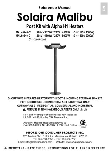
GENERAL SIZES[3.937in]Ø100mmFOOT TYP.[21.654in]Ø550mm[0.591in]3 BASE FIXING HOLES - Ø15mmEQUALLY SPACED ON P.C.D.[15.748in]Ø400mm P.C.D.15 of 20Ref No. 043477-ENRev. Ac
M AI N T E N A N C E!NOTE: For replacement lamp emitters or spare parts please contact your localdistributor quoting model type and rating from rating label. It is very important thatyour replacement lamp emitter is exactly the same as the one it was supplied with.Failure to fit the exact same type can cause the heater to prematurely fail.CAUTION: Switch off unit from the mains supply by locking off the breaker beforereplacing a lamp emitter or any maintenance procedure including cleaning.CAUTION: Should dust or dirt appear on the reflector, it is recommended that that theguard and lamp emitter are removed and the reflector is wiped with a lint-free cloth beforereassembling (see lamp emitter replacement instructions).YOUR REPLACEMENT LAMP EMITTERIt is important that when ordering a replacement lamp emitter the heater model type is specified. Failure to fit the correct lamp emitter will cause the heater to fail and become dangerous in use. Please contact your service agent to purchase your replacement lamp emitter.H ANDLING THE REPL ACEMENT LAM P EMITTERYour new lamp emitter should be handled with care and without touching the quartzglass with bare hands. A cotton glove may be used for this purpose. Remove anyfinger marks with a soft cloth and methylated spirits or rubbing alcohol. Finger markswill burn into the lamp emitters quartz glass causing premature failure.16 of 20Ref No. 043477-ENRev. Ac
REPLACING A L AMP EMITTERC AU T I O NSwitch off from the mains to the unit by locking off breaker before any attempts aremade to replace a lamp emitter. Contact your distributor for the correct replacementlamp emitter quoting model type and rating from rating label. It is important that youread through the lamp emitter replacement procedure before commencing.1. Ensure the heater and lamp emitter are cool and the power supply is disconnected fromthe mains supply.2. Remove the screws from the terminal box at the back of the heater for the lamp emitter tobe replaced and lift off the lid - see Fig. A.CONNECTOR BLOCKFig. AFig. B3. Disconnect the lamp emitter wires from the connector block by unscrewing the screwshighlighted above in Fig. B and remove the lamp emitter wires from the connector block.4. At the back of the heater, remove the plate holding the terminal box by removing the twofixing screws as shown in Fig. C.5. Pull the lamp emitter wires one at a time through the plate to remove as shown in Fig. D.FIXING SCREWSFig. CFig. D17 of 20Ref No. 043477-ENRev. Ac
6. At the front of the heater, gently remove the wire guard by prizing it away from its locatingholes at each end of the heater case (Fig. E).Fig. E7. Remove the screw from the side reflector (Fig. F) and lift the side reflector up and awayfrom the heater. Repeat at the opposite end to remove other side reflector.8. The lamp emitter wires should be pulled out of the side slots (Fig. G) and the lamp emittercan be lifted out completely. The wires can then be gently pulled forward so that they comeout from behind the reflector.SCREWFig. FFig. G18 of 20Ref No. 043477-ENRev. Ac
9. The lamp emitter can now be removed away from the heater leaving it ready to have thenew lamp emitter fitted as shown in Fig. H.Fig. H10. Refit the new lamp emitter in reverse order making sure that no wires can get trapped.Replace both ends side reflectors and their screws ensuring the lamp emitter is held firmlythen fit any other parts.19 of 20Ref No. 043477-ENRev. Ac
I M POR TANT - SAVE T H ESEI N STR UCT ION S FOR FU TU RE R EF ERENC ESolaira MalibuPost and weatherproof terminal box rain tested to: UL 2021 4th Edition by CSA Montréal Lab.Alpha H1 Heaters fitted are approved toCAN.CSA-C22.2 No. 46-13 UL 2021 3rd Edition.247748INFORESIGHT CONSUMER PRODUCTS INC.125 Traders Blvd. E Unit # 4, Mississauga, Ontario L4Z 2H3Tel: 905-568-7655 - Fax: 905-568-7521Email: info@solairaheaters.com - Website: www.solairaheaters.comDue to our policy of ongoing improvement, we reserve the right to make changes without notice. 2019 INFORESIGHT CONSUMER PRODUCTS INC.Ref No. 043477-ENRevision. Ac
The Malibu outdoor heater produces radiant heat like the sun, warming people and objects . RISK OF FIRE: Do not use as an indoor residential or household heater. INSTALLATION Use a waterproof supply cable to connect to the heater terminal box. . Fit a Alpha H1 heater to a curved tube by placing the middle bracket of the heater into the tube .