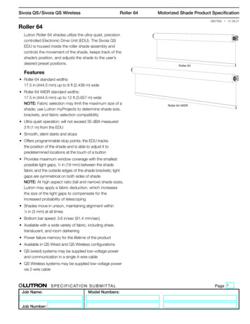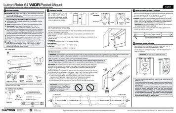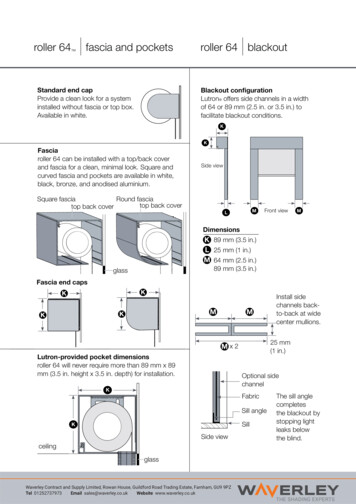
Transcription
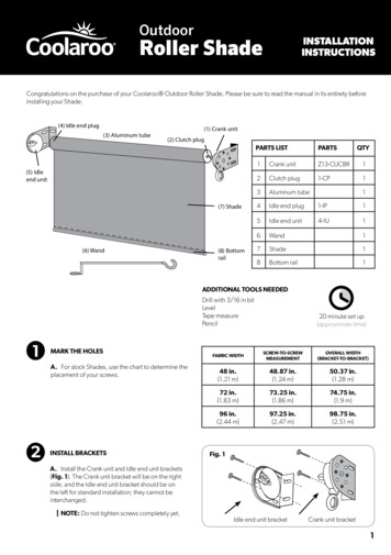
OutdoorRoller ShadeINSTALLATIONINSTRUCTIONSCongratulations on the purchase of your Coolaroo Outdoor Roller Shade. Please be sure to read the manual in its entirety beforeinstalling your Shade.(4) Idle end plug(3) Aluminum tube(1) Crank unit(2) Clutch plug(5) Idleend unit(7) Shade(6) Wand(8) BottomrailPARTS LISTPARTSQTY1Crank unitZ13-CUCBR12Clutch plug1-CP13Aluminum tube4Idle end plug1-IP15Idle end unit4-IU16Wand17Shade18Bottom rail11ADDITIONAL TOOLS NEEDEDDrill with 3/16 in bitLevelTape measurePencil1MARK THE HOLESA. For stock Shades, use the chart to determine theplacement of your screws.2INSTALL BRACKETS20 minute set up(approximate time)FABRIC WIDTHSCREW-TO-SCREWMEASUREMENTOVERALL WIDTH(BRACKET-TO-BRACKET)48 in.(1.21 m)48.87 in.(1.24 m)50.37 in.(1.28 m)72 in.(1.83 m)73.25 in.(1.86 m)74.75 in.(1.9 m)96 in.(2.44 m)97.25 in.(2.47 m)98.75 in.(2.51 m)Fig. 1A. Install the Crank unit and Idle end unit brackets(Fig. 1). The Crank unit bracket will be on the rightside, and the Idle end unit bracket should be onthe left for standard installation; they cannot beinterchanged.NOTE: Do not tighten screws completely yet.Idle end unit bracketCrank unit bracket1
B. First, insert the Clutch plug into the Crank unit (Fig. 2).Fig. 2C. Insert the Idle end plug into the Idle end unit, andsnap the Idle end plug securely into place (Fig. 3). Withthe Shade in place, adjust the brackets so they fit snuglyon each end of the Shade.Clutch plugIMPORTANT: Now go back and tighten the bracketscrews completely.Your Shade comes standard with the Clutch on theright side of the Shade and ready to be mounted onthe inside or outside of your window frame. If youpurchased a custom Shade, or intend to keep yourShade with the standard settings, you may skip thissection and proceed to the installation instructions.Fig. 3Snap Idle end pluginto Idle end unitIf you want to move the Clutch to the left side of theShade or you want to hang your Shade from the top ofthe window (or ceiling), you will need to make a fewsimple changes to your Shade before proceeding to theinstallation instructions.IMPORTANT: The screws included in yourhardware kit are for use with wood only. See yourretailer for mounting recommendations whenattaching your Shade to any other material.3ALTERNATIVE CLUTCH SETUPFig. 4Your Shade will require a non-standard installation if:you are changing the Clutch to the left side of theShade, or if you are mounting your Shade from thetop/ceiling.Removescrews tochange fromright handto left handcontrolNOTE: If you purchased a custom Shade or aredoing a standard installation, you do NOT needto make these changes.A. If you want your Clutch to be on the left side ofyour Shade, you will need to make a simple changeto your Crank unit before you install your Shade. Tomake this change, remove the four screws (Fig. 4).B. Turn the Crank unit 180 so the wand eyelet cannow hang down from the left side (Fig. 5).C. Put the screws back in, and tighten. No changeis needed to the Idle end unit, it works for right andleft mounts.2Fig. 5Rotate Crankunit 180
INSTALLATIONINSTRUCTIONS4CHANGE TO A TOP CEILING MOUNTFig. 6If you want your Shade hang from the top (forexample, the ceiling), you will need to make a simplechange to your Crank unit and Idle end unit beforeyou install your Shade.Remove screwsA. Remove the four screws from both brackets(Fig. 6).B. Turn the Crank unit 90 so the Clutch eyelethangs straight down. If the Clutch were hanging fromthe top, and turn the Idle end unit so the opening isfacing away from the window (Fig. 7), put screwsback in.Fig. 7Rotate Crankunit 90 Rotate Idle end unit 90 5INSTALL THE STANDARD WALL MOUNTFig. 8IMPORTANT: Only install your valance afteryou have installed your Shade. Refer to (Fig. 8)in order to help identify which bracket goes onwhich side.A. Remove bracket Covers (if installed):Slide off the Shade bracket covers if installed. Youwill not be using your bracket covers (Fig. 9).B. Attach the right valance bracket:Screw the RIGHT valance bracket into place (Fig. 10).Fig. 9Fig. 10C. Insert the right side of valance into valancebracket:Slide the back corner of the valance in between thelip of the top of the valance bracket. Start slidingvalance into place, moving towards the curve.Use a flathead screwdriver to open the slot on theunderside of the valance bracket to wedge the front(curved portion) of the valance into place (Fig. 11).Fig. 11D. Install the left side of valance:Slide the valance (while attached to the left valancebracket) over the left mounting bracket of the Shade.Screw bracket into place (Fig. 12).Fig. 123
Installing Inside Top MountBrackets facing down1PREPARE CRANK UNIT FOR AN INSIDEVERTICAL MOUNTFig. 13A. Start by sliding off the bracket cover on theCrank unit if installed (Fig. 13).B. Remove the four screws from the Crank unit.C. Rotate the Crank unit 90 so the wand eyelethangs straight down to the ground if the bracketwere hanging from the inside mount (Fig. 14).D. Put screws back in. You will not need the bracketcovers.2Fig. 14INSTALL CRANK UNIT, IDLE END UNIT ANDVALANCEA. Mark the holes where you are going to put yourscrews.B. Attach valance to Crank unit and Idle end unitthrough holes in top of valance or sandwich thevalance between the top of window casing and thebrackets.Fig. 15NOTE: Hardware to attach valance to Clutchand Idle end unit is not provided.C. Install the Crank unit and Idle end unit usingscrews provided (Fig. 15).Fig. 163INSTALL SHADEA. Insert the Clutch plug into the Crank unit(Fig. 16).B. Then insert the Idle end plug into the Idle endunit, and snap the Idle end plug securely into place(Fig. 17).Fig. 174
Inside Side MountBrackets facing away from window1SWITCH CLUTCH TO LEFT MOUNTFig. 18A. Remove both bracket covers, if installed (Fig.18). You will not be using your bracket covers.B. Your Shade comes standard with the clutch onthe right side of the Shade.NOTE: Only do this step if you want to moveyour clutch to the left side of the Shade.C. Remove the four screws from the Crank unit.Fig. 19D. Turn the Crank unit 180 so the wand eyelet cannow hang down from the left side (Fig. 19).E. Put the screws back in.2SLIDE VALANCE INTO BRACKETSFig. 20A. Slide the valance into the two valance brackets(Fig. 20).B. Once the valance is in its brackets, slide entirevalance into place.NOTE: Valance should stay in place on its own(Fig. 21).C. Mark your holes: With the valance andbrackets in correct position, mark holes wherescrews will go. Take down valance and brackets andpre-drill holes for screws, put valance and bracketsback into place.3Fig. 21INSTALL CRANK UNIT, IDLE END UNITA. Install Crank unit (through holes in valancebracket)into pre-drilled holes.Fig. 22B. Install Idle end unit (through holes in valancebracket) into pre-drilled holes.4INSTALL SHADEFig. 23A. Insert the Clutch plug into the Crank unit(Fig. 22).B. Then insert the Idle end plug into the Idle endunit, and snap the Idle end unit securely into place(Fig. 23).5
Persiana En Rollopara exterioresINSTRUCCIONESPARA INSTALACIÓNFelicitaciones por la compra de su persiana Coolaroo . Por favor asegúrese de leer las instrucciones antes de instalar su persiana.(4) Tapón finalinactivo(3) Tubo de aluminio(2) Tapón deembrague(1) Unidade deembragueLISTA DE PARTES(5) Unidadfinal inactiva(7) Persiana(6) Vara(8) TuboinferiorMARQUE LOS HOYOSA. Para persianas enrollables, utilizar tabla (der.) paradeterminar donde colocará los tornillos.2INSTALE LOS SOPORTESA. Instale la Unidad de manivela y el soporte dela Unidad final inactiva (Fig. 1). Para una instalaciónestándar, el soporte de la Unidad de manivela estaráen el lado derecho y el soporte de la Unidad finalinactiva estará en el lado izquierdo; esto no se puedeintercambiar.NOTA: No apriete los tornillos completamente.CT11Unidad de manivelaZ13-CUCBR2Tapón de embrague1-CP3Tubo de aluminio4Tapón final inactivo1-IP15Unidad final inactiva4-IU16Vara1117Persiana18Tubo inferior1HERRAMIENTAS ADICIONALESNECESARIASTaladro con broca de 3/16 pulgadaNivelCinta métricaLápiz1PARTES20 minutos(tiempo aproximadode instalación)ANCHO DE LAPersianaMEDIDADE TORNILLO ATORNILLOMEDIDA GENERAL(DE SOPORTE ASOPORTE)48 in.(1.21 m)48.87 in.(1.24 m)50.37 in.(1.28 m)72 in.(1.83 m)73.25 in.(1.86 m)74.75 in.(1.9 m)96 in.(2.44 m)97.25 in.(2.47 m)98.75 in.(2.51 m)Fig. 1Soporte de Unidadfinal inactivaSoporte de Unidadde manivela7
A. Primero, inserte el Tapón de embrague dentro de laUnidad de manivela (Fig. 2).Fig. 2Tapón de embragueB. Luego, inserte el Tapón final inactivo dentro de laUnidad final inactiva, asegúrese que quede fijo (Fig. 3).Con la persiana en su lugar, ajuste los soportes para quequeden cómodamente instalados en cada lado de lapersiana.IMPORTANTE: Después de seguir estasinstrucciones, vuelva y apriete los tornillos de lossoportes completamente.Su persiana viene en posición estándar con la vara enel lado derecho y está preparada para ser instalada enel interior o exterior de su ventana. Si usted obtuvosu persiana a través de una orden especial o deseamantener la persiana con sus ajustes uniformes, puedesaltar esta sección y proceder a las instrucciones de lainstalación regular.Fig. 3Enganche el Tapón final inactivoa la Unidad final inactivaSi usted desea mover la Unidad de manivela al ladoizquierdo de la persiana o desea colgar su persianaencima de la ventana (o en el techo), deberá hacerunos cambios a su persiana antes de proceder con lasinstrucciones de instalación.IMPORTANTE: Los tornillos que están incluidosen su juego de aditamentos son solamente parael uso en madera. Visite su ferretería mas cercanapar recomendaciones de que usar para montar supersiana en otras superficies.3ALTERNATIVA DE ARREGLO DE LA UNIDAD DEMANIVELAFig. 4Su persiana requerirá una instalación que no esestándar si: usted quiere cambiar el Unidad demanivela al lado izquierdo de la persiana, o ustedquiere montar la persiana en el techo.NOTA: Si usted compro una persiana especialo esta instalando una persiana uniforme, NOnecesita hacer estos cambios.A. Si usted quiere que su Unidad de manivela esteen el lado izquierdo de la persiana, usted necesitahacer un cambio sencillo a su Unidad de manivelaantes de instalar la persiana. Para hacer este cambio,quite los cuatro tornillos de los dos soportes (Fig. 4).B. Gire la Unidad de manivela 180 para que laUnidad de manivela pueda colgar hacia abajo (Fig. 5).C. Vuelva a poner los tornillos. Ningún cambio esnecesario en el Unidad final inactiva.8Fig. 5Retire lostornillos paracambiar elcontrol del ladoderecho al ladoizquierdo.Gire lo Unidadde manivela180
INSTRUCCIONESPARA INSTALACIÓN4CAMBIANDO A INSTALACIÓN EN EL TECHOFig. 6Si usted desea que su persiana cuelgue encima oen el techo, deberá hacer cambios a la Unidad demanivela y a la Unidad final inactiva antes de instalarsu persiana.Quite los tornillosA. Para hacer ese cambio, quite los cuatro tornillosde los dos soportes (Fig. 6).B. Gire la Unidad de manivela 90 para que estecuelgue directamente hacia abajo haciendo que elembrague cuelgue en el techo y gire la Unidad finalinactiva para que la abertura esté enfrente del ladomás lejos de la ventana (Fig. 7), vuelva a poner lostornillos.5INSTALACIÓN EN PARED ESTÁNDARFig. 7Gire la Unidad demanivela 90 Gire la Unidad finalinactiva 90 Fig. 8IMPORTANTE: Solo instale la cenefa una vez quehaya instalado la persiana. Consulte la (Fig. 8)en el manual de instrucciones de la cenefa paraidentificar con mayor facilidad el lugar correctopara cada soportes.A. Retire las cubiertas de los soportes (siestá instalado): Deslice y retire las cubiertas delos soportes de la persiana (si está instalado). Ya noutilizará las cubiertas de los soportes (Fig. 9).Fig. 9Fig. 10B. Instale los soportes a la derecha de lacenefa:Atornille los soportes a la DERECHA de la cenefa ensu lugar (Fig. 10).C. Inserte el lado derecho de la cenefa enel soporte de la cenefa: Deslice la esquinaposterior de la cenefa a la mitad del reborde en laparte superior del soporte de la cenefa. Comiencea deslizar la cenefa a su lugar, moviendo la hacia lacurva.Use un destornillador de cabeza plana para abrir laranura en el lado inferior del soporte de la cenefapara insertar a presión la parte frontal (sección curva)de la cenefa (Fig. 11).Fig. 11Fig. 12D. Instale el lado izquierdo de la cenefa:Deslice la cenefa (mientras está fija al soporteizquierdo) sobre el soporte de instalación izquierda dela persiana. Atornille el soporte en su lugar (Fig. 12).9
Instalación Superior En La Parte InteriorSoportes apuntando hacia abajo1PREPARE LA UNIDAD DE ELEVACIÓN PARAUNA INSTALACIÓN VERTICAL EN LA PARTEINTERIORFig. 13A. Comience por deslizar y retirar la cubierta delsoporte en la Unidad de manivela (si está instalado)(Fig. 13).B. Retire los cuatro tornillos de la Unidad demanivela.C. Gire la Unidad de manivela 90 de manera talque la Unidad de manivela cuelgue directamentehacia abajo si el soporte cuelgue desde el montajeinterior (Fig. 14).Fig. 14D. Vuelva a colocar los tornillos. Ya no necesitarálas cubiertas de los soportes.2INSTALE LA UNIDAD DE ELEVACIÓN, LAUNIDAD DEL EXTREMO INACTIVO Y LACENEFAFig. 15A. Marque los orificios en los que pondrá lostornillos.B. Fije la cenefa a la Unidad de manivela y a laUnidad final inactiva a través de los orificios en laparte superior de la cenefa. O presione la cenefaentre la parte superior del contramarco de la ventanay los soportes.NOTA: No se incluyen aditamentos para fijar lacenefa a la unidad de elevación y la Unidad finalinactiva.Fig. 16C. Instale la unidad de elevación y la unidad delextremo inactivo con los tornillos proporcionados(Fig. 15).3INSTALE LA PERSIANAA. Inserte la conexión de la Unidad de manivela(Fig. 16).B. Luego, inserte el Tapón final inactivo en laUnidad final inactiva y ajuste a presión el extremoinactivo (Fig. 17).10Fig. 17
Instalación Lateral En La Parte InteriorSoportes apuntando en dirección contraria a la ventana1CAMBIAR EMBRAGUE A INSTALACIÓN IZQUIERDAFig. 18A. Retire ambas cubiertas de los soportes (si estáinstalado) (Fig. 18). Ya no utilizará las cubiertas de lossoportes.B. La persiana y la Unidad de manivela del lado derechode la persiana son de tamaño estándar.NOTA: Realice este paso solamente si deseacambiar la Unidad de manivela al lado izquierdo dela persiana.Fig. 19C. Retire los cuatro tornillos de la Unidad de manivela.D. Gire la Unidad de manivela 180 de manera tal que laUnidad de manivela cuelgue del lado izquierdo (Fig. 19).E. Vuela a insertar los tornillos.2DESLICE LA CENEFA DE AMBOS LOS SOPORTESFig. 20A. Deslice la cenefa en ambos soportes de la cenefa(Fig. 20).B. Una vez que la cenefa esté en los soportes,deslícela completamente hasta su lugar.NOTA: La cenefa debe mantenerse en su lugar,sin ayuda (Fig. 21).Fig. 21C. Marque los orificios: Con la cenefa y lossoportes en la posición correcta, marque los orificiosdonde irán los tornillos. Retire la cenefa y los soportesy taladre previamente orificios para los tornillos.Vuelva a colocar la cenefa y los soportes en su lugar.3INSTALE LA UNIDAD DE ELEVACIÓN Y LAUNIDAD DEL EXTREMO INACTIVOFig. 22A. Instale la Unidad de manivela (en los orificios delos soportes de la cenefa) en los orificios taladradospreviamente.B. Instale la Unidad final inactiva (en los orificios delos soportes de la cenefa) en los orificios taladradospreviamente.4Fig. 23INSTALE LA PERSIANAA. Inserte el Tapón final inactivo en la Unidad finalinactiva (Fig. 22).B. Luego, inserte el Tapón final inactivo en la unidaddel extremo inactivo e insértela persiana firmementea presión en su lugar (Fig. 23).11
4 PREPARE CRANK UNIT FOR AN INSIDE VERTICAL MOUNT A. Start by sliding off the bracket cover on the Crank unit if installed (Fig. 13).B. Remove the four screws from the Crank unit. C. Rotate the Crank unit 90 so the wand eyelet hangs straight down to the ground if the bracket were hanging from the inside mount (Fig. 14).D. Put screws back in. You will not need the bracket