Transcription
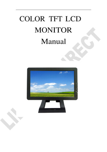
Thank you for purchasing our product.Please read this User’s Manual beforeusing the product.Change without Notice7” Q TFT LCD MONITOR (LED Backlight)USER MANUALHoltz Industries, INC.200 South Terrace CourtNewark Ohio 43055Tel: 1-800-535-0104
Safety PrecautionsFederal Communications Commission (FCC) StatementThis Equipment has been tested and found to comply with the limits for a ClassB digital device, pursuant to Part 15 of the FCC rules. These limits are designedto provide reasonable protection against harmful interference in a residentialinstallation. This equipment generates, uses and can radiate radio frequencyenergy and, if not installed and used in accordance with the instructions, maycause harmful interference to radio communications. However, there is noguarantee that interference will not occur in a particular installation. If thisequipment does cause harmful interference to radio or television reception,which can be determined by turning the equipment off and on, the user isencouraged to try to correct the interference by one or more of the followingmeasures:-Reorient or relocate the receiving antenna.-Increase the separation between the equipment and receiver.-Connect the equipment into an outlet on a circuit different from that towhich the receiver is connected.-Consult the dealer or an experienced radio / TV technician for help.You are cautioned that changes or modifications not expressly approved bythe party responsible for compliance could void your authority to operate theequipment.This device complies with Part 15 of the FCC Rules.Operation is subjectto the following two conditions:(1) This device may not cause harmful interference and,(2) This device must accept any interference received, including interferencethat may cause undesired operation.2
Table of ContentSafety Precaution. . 2Table of Content. . 3Features. 4Package Contents . . 4TFT Installation 5Signal Cable Description . . 6Control Cable Description . 8Front Panel Control. 9OSD Menu . . . 10Video Setting Menu . . 11Display Setting Menu 12Camera Setting Menu . 13Information . 16Vehicle Installation . 17Specification . . 18Attachment . . 193
FeaturesAdvanced OSD Menu for easy useSupport up to 4 CCD Camera Inputs (Mini din Connector)Extra RCA Input for Multimedia (VCD, DVD, Game Device)Provide 1 Live Video / Audio Signal Output / Cam OutAuto Detection for NTSC / PAL SystemSignal Trigger for CAM A / CAM B / CAM C /CAM R / AV ViewAuto Brightness Adjustment by light sensorOSD Control for Individual Normal / Mirror Camera ImageSwitch Timer (2-100 sec) Step Selection via OSD (CAM A / CAM B / CAM C /CAMR / AV)Supported 9.6V 32V Car power system workingPackage ContentsItemQty.1.7” LCD Monitor12.Sun-hood13.Mounting Bracket14. Accessories25.Control Cable16.User Manual14
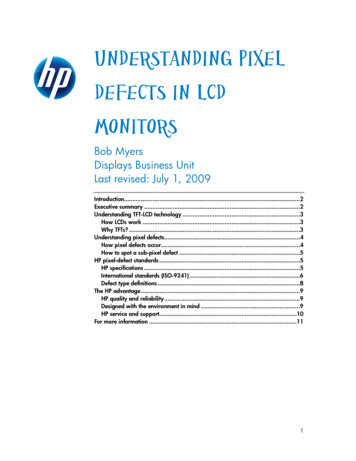
TFT InstallationStep 1Check the package and make sure all parts areincludedStep 2Clip the sun-hood on to the monitorStep 3Make sure it is installed properlyStep 4Install the monitor on to the bracketStep 5Adjust the monitor to an appropriate / comfortableviewing angle before tightening the screwsStep 6Monitor installation is now completed.Each control cable wire is attached with a sticker toindicate its signal function.Referred to theidentification sticker for further installation.5
Signal Cable Description1. CAM A (Mini din)For 1st camera connection2. CAM B (Mini din)For 2nd camera connection3. CAM C (Mini din)For 3rd camera connection4. CAM R (Mini din)For 4th camera connection5. LIVE VIDEO OUT (White Color RCA Jack)On screen video loop out (for recording, second monitor or other device)6. LIVE AUDIO OUT (Black Color RCA Jack)On screen audio loop out (for recording, second monitor or other device)7. AV VIDEO IN (Yellow Color RCA Jack)Connection for any Video signal (DVD, VCD, Game)8. AV AUDIO IN (Red Color RCA Jack)Connection for any Audio signal (such as DVD, VCD, Game)9. CAM OUT (Green Color RCA Jack)Video loop out (for recording, second monitor or other device)6
Mini Din Pin Assignment* Type 1 (Standard):53641. -----4. GND2. -----5. 12V3. Audio6. Video*Type 2 (Optional):211. GND4. 12V2. ------5. -------3. Video6. AudioFunction of the AudioCam AAudio from Cam ACam BAudio from Cam BCam CAudio from Cam CCam RAudio from Cam RCam A Cam BAudio from Cam ACam C Cam RAudio from Cam RCam A Cam RAudio from Cam RCam R Cam BAudio from Cam RCam A Cam CAudio from Cam ACam C Cam BAudio from Cam CCam R / Cam ABAudio from Cam RQuadAudio from Cam RAVAudio from AV※ Cam Out: Composite video loop out signal to recorder, monitor or other device.※ Live Video/Audio Out: On screen video/audio signal loop out to recorder, monitoror other device.7
Control cable DescriptionDon’t connect the red wire (power wire) of thisproduct directly to the battery. Connect the redwire of this product to the ACC of the ignition keyswitch. Failure to do so may result in permanentdamage of the product.WIRE COLORFUNCTIONREDACC POWERBLACKGNDWHITEParking ControlREMARKON SCREEN VIEWActive GNDAVYELLOWORANGEBLUELeft turn Control(Correspond toCAM A)Active Power LevelConnect to DirectionLight(Left Turn Light)Right turn(Correspond toCAM B)Active Power LevelConnect to DirectionLight(Right Turn Light)Reverse Control(Correspond toCAM R)Active Power LevelConnect to ReverseCAM ACAM BCAM R1. The control cable sequence: Reverse Right / Left Park (AV)2. With car power is on, the monitor power is off, when making a reverse / right / left turn, themonitor will display default screen.3. *When pull the hand break, user need to press SOURCE button again to display AV IN picture.8
Front Panel ControlPOWERPress the power button to activate the monitor or to keep the monitorunder stand by mode. Red light for stand by, Green light is turn on.MENUPress the menu button to pop up OSD menu.UPScroll up the function item or increase value.DOWNScroll down the function item or decrease value.SELECT With power on press this button to select image sequence.CAM A CAM B CAM C CAM R CAM A B CAM C RCAM A R CAM R B CAM A C CAM C B CAM R/ABCAM R AB CAM A With pull hand break, press this button to select image sequenceAV CAM A B CAM C R CAM A R CAM R B CAM A CCAM C B CAM R/AB CAM R AB CAM A CAM B CAM CCAM R AV .9
JUMPPress this button, it can switch CAM A, CAM B, CAM R recurrently.With pull hand break and check the Jump option is ON, pressthis button to select image sequenceQUAD SEQ CAM A B CAM C R CAM A R CAM R BCAM A C CAM C B CAM R/AB CAM R AB CAM ACAM B CAM C CAM R, The default value is QUAD.OSD Menu1.Press the MENU button to enter to the OSD Menu2.Press UP & Down button to select the setting you wish to proceed.The picture of the content will turn rise high to identify your selection.Press UP & Down button to adjust your setting value.3.Press the MENU button once back to submenu and then select theBACK item in order to return to OSD menu.Enter to Main Menu10
Video Setting MenuThis menu set up contains different setting for the TFT LCD.BrightnessProvide adjustment for shade and brightness level of TFT display.Setting value from 0 100. Default value is 50.ContrastProvide adjustment for the light and dark level of the TFT display.Setting value from 0 100. Default value is 50.SaturationProvide adjustment for the light intensity level of TFT display.Setting value from 0 100. Default value is 50.HueProvide adjustment for the lightness and colorfulness level of TFT display.Setting value from 0 100. Default value is 50.(Only in NTSC system is available.)SharpnessProvide adjustment for the edge contrast (acutance) level of TFT display.Setting value from 0 100. Default value is 50.BackReturn to OSD menu selection screen.11
Display Setting MenuThis menu set up contains the on screen identification and the activationof the distance gage.Light SensorSelect “Auto” to activate the auto brightness adjustment function for screen.Or select “Night” to reduce the brightness for screen.Default value is Day.CAM DisplaySelect “ON” to show the source of video input title on screen or “OFF” tokeep it invisible. Default value is ON.Guiding LineSet the distance gauge “ON” to show the distance gauge on screen whilereserving or “OFF” to deactivate. Default value is ON.(This “Guiding Line” is for user’s reference only)OSD LockThis function provides protection when an unauthorized person tries toaccess the OSD settings. UP and DOWN key press simultaneously for over5 seconds to unlock. Default value is OFF.※Users must turn on LCD in order to run unlock process. All functionbuttons are still working during OSD Menu lock up period.BackReturn to OSD menu selection screen.12
Camera Setting MenuThis menu set up contains the on Camera and Jump setting.Normal/MirrorSet the all camera’s display mode. CAM ASelect “Mirror” to activate the mirror function for different camerasor “Normal” for a normal image.Default value is Normal.CAM BSelect “Mirror” to activate the mirror function for different camerasor “Normal” for a normal image.Default value is Normal.CAM CSelect “Mirror” to activate the mirror function for different camerasor “Normal” for a normal image.Default value is Normal.CAM RSelect “Mirror” to activate the mirror function for different camerasor “Normal” for a normal image.Default value is Mirror.13
JumpJump provide automatically channel switch function.Setting value from SEQ, A B, C R, A R, R B, A C, C B, R/AB, R AB,A ,B , C, R, QUAD. Default value is QUAD.Dir ImageThe screen image setting of this panel during left / right turn:TRIPLE: When you are making a right turn or left turn, the screen ofpanel will display triple images for left hand side, righthand side and rear view when you are making a right turnor left turn.DUAL: With proper wiring, the screen will display dual image forboth rear and right hand side view when making a right turn.While left turning, the screen will show dual image for bothrear and left hand side view.SINGLE: Screen of touch panel shows only single picture on directionturn. The screen will show only left side view on left turn andonly right side view on right turn.A B, B A : With proper wiring, When you are making a left turn thescreen will display Cam A Cam B image. When make a rightturning, the screen will show Cam B Cam A image on thescreen.Default value is SINGLE.Rear SetupThe screen image setting of this panel during reverse gear:R:Screen will display single image for Cam R only.R A:Screen will display dual image for both Cam R and Cam A.R B:Screen will display dual image for both Cam R and Cam B.R/AB:Screen will display triple image from Cam R、Cam A、Cam B.14
R AB:Screen will display triple image from Cam R、Cam A、Cam B.Default value is R.CAM OutComposite video loop out to recorder, monitor or other device.QUADRecording or viewing from the output device in quad modeCAM ARecording or viewing from the output device for CAMA imageCAM BRecording or viewing from the output device for CAMB imageCAM CRecording or viewing from the output device for CAMC imageCAM RRecording or viewing from the output device for CAMR imageDefault value is QUAD.SEQ TimeSetting Jump dwell value from 2 100.Default value is “2”.BackReturn to OSD menu selection screen.15
Information MenuThis menu can set device to default value and leave the OSD menu.DefaultRecall factory default.ExitExit OSD menu to live screen.16
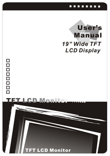
Vehicle InstallationCam eraGreenYellow1M0M1MRed2MYellowRed3MGreena. Install Camera R (for rear view)b. Use a measuring tool to mark out the distance behind the vehicle.c. Adjust the viewing angle of the camera so that the distance gage shown fromthe TFT match to the distance marks behind the vehicle.d. Switch to Rear view with source button, the screen always display on 16:9While rear viewing, the screen always display on 16:9.SOURCE button:Rear viewing:161699e.17
SpecificationChannel DisplayFull OnlyScreen size7 inchActive area153.6(H) x 86.64(V)Pixel Pitch0.192(H) x 0.1805(V)Resolution800(H) x 480(V)Viewing angleUP:70 / Down:60 / Left: 75 / Right:75 Power source:DC9.6V DC32VContrast ratio500:1※※Brightness450 cd/m2※AV Video InConnectorRCA TypeInput Signal1VppImpedance75 OhmsCamera MINI DIN InConnector6 PIN MINI DIN Type (Standard)Input video signal level1VppImpedance75 OhmsInput audio signal level1VppPower output for camera DC12V (300mA Max)AV Audio InConnectorRCA TypeInput audio signal level1VppImpedance1K OhmsComposite Video Live OutConnectorRCA TypeOutput signal level1VppImpedance75 OhmsAudio Live OutConnectorRCA TypeInput signal level1VppImpedance1K OhmsCAM OutConnectorRCA TypeInput signal level1VppImpedance75 OhmsDimensionWxHxD:182.8 x168.5 x 103.6mmWeightN.W./G.W.: 1.5kg / 2.1kgEnvironmental:Operation temperature-20 70 (14 158 )Storage temperature-30 80 (-22 176 )Humidity20%-80%WeatherproofIPX1※The brightness and contrast ratio specifications are from panel specification. Design andSpecifications are subject to change without notice.18
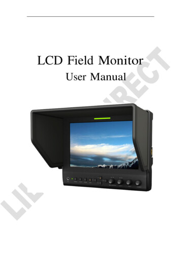
AttachmentAttachment 1:Dimension Chart19
Attachment 2:Installation Chart2085-ML074Q-A001G-B
7" Q TFT LCD MONITOR (LED Backlight) USER MANUAL Holtz Industries, INC. 200 South Terrace Court Newark Ohio 43055 Tel: 1-800-535-0104 . 2 . Monitor installation is now completed. Each control cable wire is attached with a sticker to indicate its signal function.