Transcription
AC / HP PuronR Refrigerant SystemsSingle---Stage, Two---Stageand Variable Speed ModelsResidential Piping and Long Line GuidelineTABLE OF CONTENTSSafety Considerations . . . . . . . . . . . . . . . . . . . . . . . . . . . . . . . . . . . . . . . . . . . . . . . . . . . . . . . . . . . . . . . . . . . . . . . . . . . . . . . . . . . . . . . . . . 2Definitions . . . . . . . . . . . . . . . . . . . . . . . . . . . . . . . . . . . . . . . . . . . . . . . . . . . . . . . . . . . . . . . . . . . . . . . . . . . . . . . . . . . . . . . . . . . . . . . . . . . . 2Introduction . . . . . . . . . . . . . . . . . . . . . . . . . . . . . . . . . . . . . . . . . . . . . . . . . . . . . . . . . . . . . . . . . . . . . . . . . . . . . . . . . . . . . . . . . . . . . . . . . . 3General Limitations . . . . . . . . . . . . . . . . . . . . . . . . . . . . . . . . . . . . . . . . . . . . . . . . . . . . . . . . . . . . . . . . . . . . . . . . . . . . . . . . . . . . . . . . . . . . 3Interconnecting Tubing and Fitting Losses . . . . . . . . . . . . . . . . . . . . . . . . . . . . . . . . . . . . . . . . . . . . . . . . . . . . . . . . . . . . . . . . . . . . . . . . . 4Metering Device — Long Line Cooling . . . . . . . . . . . . . . . . . . . . . . . . . . . . . . . . . . . . . . . . . . . . . . . . . . . . . . . . . . . . . . . . . . . . . . . . . . . . 4Heat Pump Piston Sizing — 1 and 2--Stage . . . . . . . . . . . . . . . . . . . . . . . . . . . . . . . . . . . . . . . . . . . . . . . . . . . . . . . . . . . . . . . . . . . . . . . . 5Heat Pumps Containing Electronic Expansion Valve (EXV for heating mode) . . . . . . . . . . . . . . . . . . . . . . . . . . . . . . . . . . . . . . . . . . . 5Liquid Line Solenoid — Long Line Heat Pump Heating . . . . . . . . . . . . . . . . . . . . . . . . . . . . . . . . . . . . . . . . . . . . . . . . . . . . . . . . . . . . . 5Charging Information . . . . . . . . . . . . . . . . . . . . . . . . . . . . . . . . . . . . . . . . . . . . . . . . . . . . . . . . . . . . . . . . . . . . . . . . . . . . . . . . . . . . . . . . . . 5Vapor Line Sizing & Cooling Capacity Loss . . . . . . . . . . . . . . . . . . . . . . . . . . . . . . . . . . . . . . . . . . . . . . . . . . . . . . . . . . . . . . . . . . . . . . . 5Applications . . . . . . . . . . . . . . . . . . . . . . . . . . . . . . . . . . . . . . . . . . . . . . . . . . . . . . . . . . . . . . . . . . . . . . . . . . . . . . . . . . . . . . . . . . . . . . . 6 - 91 and 2--Stage Long Line Applications -- Units on Equal Level . . . . . . . . . . . . . . . . . . . . . . . . . . . . . . . . . . . . . . . . . . . . . . . . . . . . . . 61 And 2--Stage Long Line Applications -- Indoor Unit Above Outdoor Unit . . . . . . . . . . . . . . . . . . . . . . . . . . . . . . . . . . . . . . . . . . . . 71 And 2--Stage Long Line Applications -- Outdoor Unit Above Indoor Unit . . . . . . . . . . . . . . . . . . . . . . . . . . . . . . . . . . . . . . . . . . . . 8Variable Speed Long Line Applications . . . . . . . . . . . . . . . . . . . . . . . . . . . . . . . . . . . . . . . . . . . . . . . . . . . . . . . . . . . . . . . . . . . . . . . . . 9Puronr Refrigerant Quick Reference Guide . . . . . . . . . . . . . . . . . . . . . . . . . . . . . . . . . . . . . . . . . . . . . . . . . . . . . . . . . . . . . . . . . . . . . . . 10
SAFETY CONSIDERATIONSOnly trained service technicians familiar with standard service instructions and training materials should attempt installation, service,and repair of these units. Improper installation, adjustment, alteration, service, maintenance, or use can cause explosion, fire, electricalshock, or other conditions which may cause death, personal injury, or property damage. Consult a qualified installer, service agency, oryour distributor or branch for information or assistance. The qualified installer or agency must use factory----authorized kits oraccessories when modifying this product. Refer to the individual instructions packaged with the kits or accessories when installing.Follow all safety codes. Wear safety glasses, protective clothing, and work gloves. Use quenching cloth for brazing operations. Havefire extinguisher available. Read these instructions thoroughly and follow all warnings or cautions included in literature and attached tothe unit. Consult local building codes and National Electrical Code (NEC) for special requirements.Recognize safety information. This is the safety--alert symbol. When you see this symbol on the unit and in instructions ormanuals, be alert to the potential for personal injury. Understand these signal words; DANGER, WARNING, and CAUTION. Thesewords are used with the safety--alert symbol. DANGER identifies the most serious hazards which will result in severe personal injury ordeath. WARNING signifies hazards which could result in personal injury or death. CAUTION is used to identify unsafe practiceswhich may result in minor personal injury or product and property damage. NOTE is used to highlight suggestions which will result inenhanced installation, reliability, or operation.!WARNINGELECTRICAL SHOCK HAZARDFailure to follow this warning could result in personal injury or death.All equipment should be installed in accordance with accepted practices and unit Installation Instructions, and in compliance withall national and local codes. Power should be turned off when servicing or repairing electrical components. Extreme cautionshould be observed when troubleshooting electrical components with power on. Observe all warning notices posted on equipmentand in instructions or manuals.!WARNINGEXPLOSION AND PERSONAL SAFETY HAZARDFailure to follow this warning could result in personal injury, equipment damage or improper operation.Refrigeration systems contain refrigerant under pressure. Puronr refrigerant (R--410A) systems operate at higher pressure thanstandard R--22 systems. Use only service equipment and components rated for Puronr refrigerant. Extreme caution should beobserved when handling refrigerants. Wear safety glasses and gloves to prevent personal injury. During normal system operations,some components are hot and can cause burns. Rotating fan blades can cause personal injury. Appropriate safety considerationsare posted throughout this manual where potentially dangerous techniques are addressed.Refrigeration systems contain refrigerant under pressure. Extreme caution should be observed when handling refrigerants. Wear safetyglasses and gloves to prevent personal injury. During normal system operations, some components are hot and can cause burns.Rotating fan blades can cause personal injury. Appropriate safety considerations are posted throughout this manual where potentiallydangerous techniques are addressed.DEFINITIONSThis Guideline covers all residential split system air conditioner and heat pump products using Puron refrigerant includingtwo--stage and variable speed models.2
INTRODUCTIONAn application is considered Long Line, when the refrigerant level in the system requires the use of accessories to maintain acceptablerefrigerant management for systems reliability. Accessory requirements depend on the system type, and are defined in this document.Defining a system as long line depends on the liquid line diameter, indoor metering device (piston or TXV), actual length of the tubing,and vertical separation between the indoor and outdoor units.For Air Conditioner systems, the charts below show when an application is considered Long Line:AC with Puronr Refrigerant Long Line Description ft (m) Beyond these lengths, a TXV is requiredTotal LengthTXV required beyond 50 ft. (15.2 m)Outdoor Unit Above or Below Indoor UnitTXV required beyond 20 ft. (6.1 m)AC with Puronr Refrigerant Long Line Description ft (m) (Beyond these lengths, long line accessories are required)Liquid Line SizeUnits On Same LevelNo accessories needed within allowed lengthsOutdoor Below IndoorNo accessories needed withinallowed lengthsOutdoor Above Indoor5/16 TXV120 (36.6)50 (15.2) vertical or 120 (36.6) total120 (36.6)3/8 TXV80 (24.4)35 (10.7) vertical or 80 (24.4) total80 (24.4)1/4 TXV175 (53.3)For Heat Pump systems, the chart below shows when an application is considered Long Line:HP with Puronr Refrigerant Long Line Description ft (m) (Beyond these lengths, long line accessories are required)Liquid Line SizeUnits On Same LevelOutdoor Below IndoorOutdoor Above Indoor3/8 TXV80 (24.4)20 (6.1) vertical or 80 (24.4) total80 (24.4)NOTE: Multi--stage and variable speed products must use TXV indoor metering deviceNOTE: All single stage heat pumps must use TXV indoor metering deviceLong line applications are clearly defined in this Guideline, and must be treated differently from standard systems. A long line systemrequires special consideration for the following reasons:Additional refrigerant chargeRefrigerant migration controlOil return concernsCapacity lossesMetering device adjustmentsLonger line sets require additional refrigerant charge that must be managed throughout the entire range of possible ambient conditions.Off--cycle refrigerant migration that results in excess refrigerant in the compressor at start up, or condensed liquid refrigerant in thesuction line at start up must be avoided for compressor reliability. Follow all accessory requirements in this Guideline to controloff--cycle refrigerant migration.Another concern is proper line set sizing and construction to control oil return to the compressor, and minimize capacity losses. Inresidential applications, proper suction line sizing is critical to achieve adequate oil return, and maintain expected system performance.Oil return in heating mode is different from cooling mode thus, in some cases, heat pumps have additional line set limitations from airconditioning units. Follow all suction line sizing recommendations to ensure system performance and adequate oil return forcompressor lubrication.The third concern is refrigerant metering. Equivalent length and elevation changes affect pressure drop in refrigerant lines. Theseeffects must be considered when sizing liquid lines and orifice--metering devices. Most current indoor products utilize a TXV forcooling mode metering, however, some fan coil models use a piston for refrigerant metering in cooling mode. Proper piston sizing is aconcern where piston metering devices are used. Follow piston change recommendations in this Guideline for proper equipmentoperation (see Tables 7 & 10).Testing has been done to determine limitations for the application of 1/4 and 5/16 inch liquid lines in cooling only systems. Thelimiting factor when sizing liquid lines is pressure drop. Equivalent length and vertical separation both contribute to the pressure dropin a liquid line. The liquid line sizing charts in this guideline specify whether the metering device is a piston or TXV.NOTE: When an application is “Long Line”, accessory requirements differ depending on product type. Requirements are listed inthe individual product--type sections.SSSSSGENERAL LIMITATIONSLiquid Lines -- AC OnlyLiquid line diameters of 1/4” and 5/16” are allowed with published limitations for cooling--only system with TXV device only. Use3/8” liquid lines for systems with piston indoor metering device. Using smaller liquid lines affects the maximum allowable equivalentlength and when the application qualifies as long line. Elevation changes between the indoor and outdoor units also affect allowableequivalent lengths. (See tables 3, 5, and 8 to properly size liquid lines.)NOTE: Using 1/4 and 5/16” liquid lines within the limits provided, result in no capacity or efficiency changes to the system.Liquid Lines -- Heat PumpLiquid line sizing for heat pumps is currently limited to 3/8”. Contact your factory representative for alternate liquid line sizing for heatpump applications.Suction LinesRefer to individual Product Data Sheets for acceptable suction line diameters and related capacity effects.3
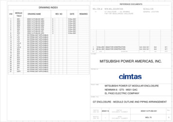
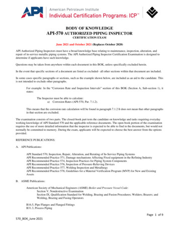
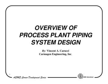
INTERCONNECTING TUBING AND FITTING LOSSESChoosing the proper tubing diameters is critical for reliable long line applications. For proper suction line sizing, see suction line sizingcharts in individual unit Product Data Sheets. These charts show all acceptable suction line diameters and related performance databased on total equivalent length. See Tables 3, 5, and 8 for the allowable liquid tubing diameters for both single--stage and two--stage.NOTE: Only 3/8” diameter liquid lines are allowed for variable--speed outdoor units.Refrigerant tubing must be measured both in terms of actual length and equivalent length. Use actual length for limitations andrefrigerant charge calculation. The maximum liquid line length will vary depending on diameter and elevation change between indoorand outdoor units. Equivalent length takes into account pressure losses from both tubing length and losses due to fittings andaccessories, such as elbows, liquid line solenoid and filter drier. Losses from fittings are expressed in equivalent length, meaning thelength of straight tubing that would have the same pressure loss as the fitting. See Table 1 for equivalent lengths of commonly usedfittings and accessories; maximum equivalent length allowed is up to 250 ft (76.2 m) See Tables 3, 5, 8, 11 and 12 for maximum totalequivalent length.Calculate total equivalent length by adding linear (actual) length of the tubing required and the equivalent length of all elbows andaccessories used. This data can be found in the outdoor unit Product Data.Example: A 4--ton system using 7/8 in. diameter line set has a total tubing length of 165 ft. The tubing configuration uses four standard90 elbows and two 90 long--radius elbows. Checking Table 1, the total equivalent length is calculated as:165 ft straight tubing (four standard 90 elbows x 2 ft) (two long--radius 90 elbows x 1.4 ft) 165 ft. 8 ft 2.8 ft 175.8 fttotal equivalent length.ACB90 STD45 STD90 LONG RADA01058Fig. 1 – Tube Bend LossesTable 1 – Fitting Losses in Equivalent FeetTube Size O.D. (In.)1/25/83/47/81---1/890 Std (A)1.21.61.82.02.6Fitting--- Reference Diagram in Fig. 190 Long---Rad (B)0.81.01.21.41.7Liquid Line SolenoidFilter Drier45 Std (C)0.60.80.91.01.3126METERING DEVICE — LONG LINE COOLINGIn current equipment, most indoor units use a hard--shutoff TXV for metering in the cooling mode. This provides adequate refrigerantmigration protection for all applications. For fan coils using piston (or fixed orifice) metering device, the addition of a TXV is requiredat 50 ft. (15.2 m) total length or when the units have a vertical separation of 20 ft (6.1 m) or more. Once a TXV is added, otheraccessories are required as shown.4
HEAT PUMP PISTON SIZING — 1 AND 2--STAGEAn AccuRater (fixed orifice) is used for refrigerant metering in the heating mode in 1 and 2--stage heat pumps. This fixed expansiondevice must be changed from the factory--supplied AccuRater based on indoor/outdoor vertical separation and system capacity. Forhorizontal applications up to 200 ft (61 m) linear length and 250 ft (76 m) total equivalent length, no heating piston change isnecessary.When sizing the heating piston for installations where the outdoor unit is below the indoor unit, use Table 7. When outdoor unit islocated above indoor unit, use Table 10.Example: The factory supplied AccuRater for a single--stage 3--ton heat pump is a number 57. A system is installed with 200equivalent ft of line set. Approximately 60 ft (18.3 m) is horizontal and the outdoor unit is 140 ft (42.7 m) above the indoor unit. Table10 shows the AccuRater piston change to be 6. The new piston size is 57 6 63. If a 63 is not produced, round up to the nextlarger available piston size.On the same heat pump, if the outdoor unit was located 49 ft (14.9 m) below the indoor unit, Table 7 shows the piston change to be 57-- 2 55. If a 55 piston is not produced, round up to the next available size.HEAT PUMPS CONTAINING ELECTRONIC EXPANSION VALVE(EXV FOR HEATING MODE)Variable--speed heat pumps contain an EXV for refrigerant metering in the heating mode, and will self--adjust for longer line sets.LIQUID LINE SOLENOID — LONG LINE HEAT PUMP HEATINGSince AccuRater do not provide off--cycle refrigerant migration protection in the heating mode, a liquid line solenoid is required forsingle--stage and two--stage heat pump long line applications. A liquid line solenoid is also required for long line applications ofGreenspeedt (25VNA0) and Extremet (280BNV) units. A bi--flow solenoid valves provide flow control protection only in thedirection of the arrow molded into the valve. The arrow must point toward the outdoor unit for off--cycle refrigerant control in theheating mode. The arrow shows the direction of flow control. The solenoid should be installed within 2 ft. (609.6 mm) of the outdoorunit. See the Product Data of individual equipment for part numbers.NOTE: Equivalent length of the liquid line solenoid should be added to the total equivalent length of the tubing.CHARGING INFORMATIONUse subcooling as the primary method for charging longline applications. Outdoor units are pre--charged for 15 ft (4.6 m) of 3/8 liquidline. When using different length diameter liquid lines, charge adjustments are required. See Table 2 for charge adjustments required.The charge adjustment will depend on the liquid line diameter used. See unit installation instructions for proper charging procedure.For all long line applications, pressure drop and subcooling loss become a concern. In these applications, a minimum of 10 F (5.6 C)of subcooling is required for all liquid line diameters to ensure no refrigerant flashing occurs before the TXV metering device.Systems should be charged to 10 subcooling or the rating plate subcooling, whichever is greater. Ensure the indoor and outdoorconditions are within allowable limits to charge by subcooling -- indoor between 70 F and 80 F (21.1 C and 26.7 C), outdoor between65 F and 100 F (18.3 C and 37.8 C). If outside these limits, weight in charge.The amount of factory--charge can be found on the unit rating plate or in the Product Data literature.Table 2 – Refrigerant Charge AdjustmentsLiquid Line Size3/85/161/4Puron Charge (oz/ft)0.60(Factory charge for lineset 9 oz)0.400.27Units are factory--charged for 15 ft (4.6 m) of 3/8” lineset. Factory charge for 3/8 lineset is 9 oz. When using other length or diameterliquid lines, charge adjustments are required per chart above.Charging Formula:[(Lineset oz/ft x total length) – (factory charge for lineset)] charge adjustmentExample 1: System has 15 ft of line set using existing ¼” liquid line. What charge adjustment is required?Formula:(.27 oz/ft x 15ft) – (9 oz) (-4.95) oz.Net result is to remove 4.95 oz of refrigerant from the systemExample 2: System has 45 ft of existing 5/16” liquid line. What is the charge adjustment?Formula:(.40 oz/ft. x 45ft) – (9 oz.) 9 oz.Net result is to add 9 oz of refrigerant to the systemNOTE: Conditions must be favorable for charging by subcooling method. Indoor temperature must be 70 F to 80 F (21.1 C to 26.7 C),and outdoor temperature must be 70 F to 100 F (21.1 C to 37.8 C). If outside these conditions, adjust charge for long line sets byweigh--in method.VAPOR LINE SIZING AND COOLING CAPACITY LOSSAcceptable vapor line diameters provide adequate oil return to the compressor while avoiding excessive capacity loss. Charts withacceptable suction line diameters and capacity losses are shown in the Product Data for each individual model number. Please refer tothe Product Data sheets for this information5
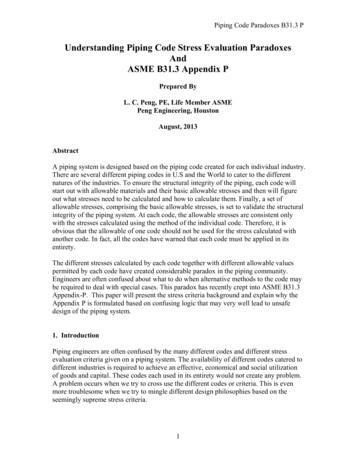
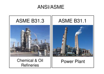
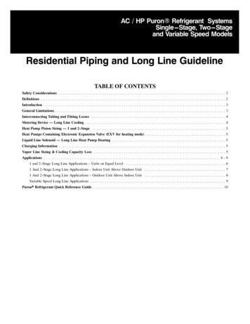
APPLICATIONS1 and 2--stage Long Line Applications -- Units on Equal Level200ft (60.1m) MaxLSV (Heat Pump Only)Fig. 2 – Equal--Level Outdoor/Indoor UnitSSSSSSSSSMaximum actual length is 200 ft (60.1 m)Maximum equivalent length is 250 ft (76.2 m)A hard shut--off TXV is required on the indoor unit beyond 50 ft (15.2 m), other accessories per lengths and heights in Table 4below.A hard start kit (capacitor and relay) is required on 1--stage unitsA crankcase heater must be installed on compressor if not factory--suppliedVapor line should slope toward indoor unitHeat pump only – Bi--flow liquid line solenoid must be installed within 2 ft (0.61 m) of outdoor unit with arrow pointing towardsoutdoor unit.Heat Pump Only – no heating piston adjustment required.See Product Data for specific unit for accessory part numbers.Table 3 – Maximum Total Equivalent LengthUnits on Equal LevelSize1824SystemTypeLiquidLineDiameterw/ TXVMaximum Total Equivalent Length{: Outdoor unit BELOW IndoorVertical Separation ft (m)0---5(0--- 1.5)6---10(1.8--- 3.0)11 ---20(3.4 ---6.1)21--- 30(6.4--- 9.1)31--- 40(9.4 ---70(18.6---21.3)71--- 80(21.6--- 24.4)AC Only1/415015012510010075--- ------ ------ ---AC HP3/8250*250*250*250*250*250*250*250*AC Only1/47575755050--- ------ ------ ------ ---AC 50*250*250*250*250*250*250*250*250*AC Only1/430--- ------ ------ ------ ------ ------ ------ ------ ---AC Only5/16175225*20017512510075--- ------ ---AC/HP3/8250*250*250*250*250*250*250*250*250*AC Only5/1617515015010010010075--- ------ ---AC/HP3//8250*250*250*250*250*250*250*250*250*AC Only5/16125100100757550--- ------ ------ ---AC/HP3/8250*250*250*250*250*250*250*250*15048, 49AC/HP3/8250*250*250*250*250*250*230160--- ---54,60, 61AC/HP3/8250*250*250*225*190150110--- ------ ---3036, 3742, 43* Maximum actual length not to exceed 200 ft (61 m){ Total equivalent length accounts for losses due to elbows or fitting.--- --- outside acceptable rangeTable 4 – AC / HP with Puronr Refrigerant Long Line Description ft (m)Beyond these lengths, long line accessories are requiredAC1 & 2---StgAC Liquid Line Size1/4 TXV5/16 TXV3/8 TXVUnits On Same LevelNo accessories needed within allowed lengths120 (36.6)80 (24.4)HP1 & 2---StgHP Liquid Line Size3/8 TXVUnits On Same Level80 (24.4)6
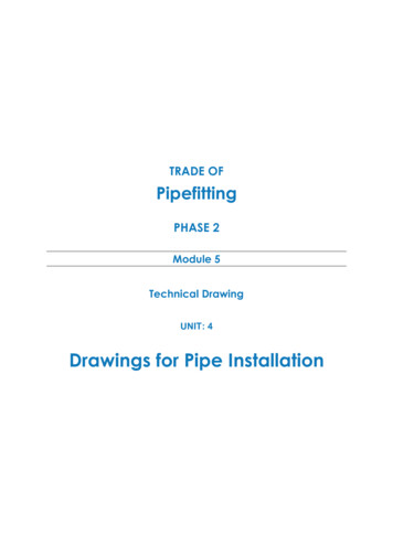
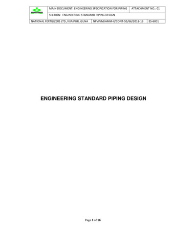
1 and 2-- stage Long Line Applications - Outdoor Unit Below Indoor UnitSee Table 5 forMaximum Height andEquivalent LengthFig. 3 – Outdoor Unit Below Indoor UnitMaximum actual length and lift per Table 5 belowA hard shut--off TXV is required beyond 50ft (15.2 m) total length or 20ft (6.1m) vertical separation, other accessories perlengths and heights in Table 6 below.A hard start kit (capacitor and relay) is required on 1--stage unitsA crankcase heater must be installed on compressor if not factory--suppliedHeat pump only – Bi--flow liquid line solenoid must be installed within 2 ft (0.61 m) of outdoor unit with arrow pointing towardsoutdoor unit.Heat Pump Only – outdoor piston adjustment required per Table 7 belowAn inverted vapor--line trap must be installed at indoor unit. The top peak of trap must be greater than height of indoor coil.Unit must be charged to 10 deg subcooling or nameplate subcooling, whichever is greater.See Product Data for specific unit for accessory part Table 5 – Maximum Total Equivalent Length{Outdoor Unit Below Indoor UnitSystemTypeLiquidLineDiameterw/ TXV0---5(0--- 1.5)6---10(1.8--- 3.0)11 ---20(3.4 ---6.1)21--- 30(6.4--- 9.1)31--- 40(9.4 ---70(18.6---21.3)71--- 80(21.6--- 24.4)AC OnlyAC OnlyAC/HPAC OnlyAC OnlyAC/HPAC OnlyAC OnlyAC/HPAC OnlyAC/HPAC 175250*125250*250*250*150250*250*75250*250*--- 50*--- 0*--- *--- --125250*100250*75250*250*19075250*250*--- --225*250*--- --100250*100250*50250*250*150--- --250*250*--- --175250*--- --75250*75250*--- --250*230110--- --225*250*--- --125250*--- ----- --250*--- --250*--- --250*160--- ------ --150250*--- --100250*--- ----- --250*--- --250*--- --150--- ----- ---Maximum Total Equivalent Length{: Outdoor unit BELOW Indoor Vertical Separation ft (m)* Maximum actual length not to exceed 200 ft (61 m){ Total equivalent length accounts for losses due to elbows or fitting. See the Table 1 for details.--- --- outside acceptable rangeTable 6 – AC / HP with Puronr Refrigerant Long Line Description ft (m)Beyond these lengths, long line accessories are requiredAC1 & 2---StgAC Liquid Line Size1/4 TXV5/16 TXV3/8 TXVOutdoor Below IndoorNo accessories needed within allowed lengths50 (15.2) vertical or 120 (36.6) total35 (10.7) vertical or 80 (24.4) totalHP1 & 2---StgHP Liquid Line Size3/8 TXVOutdoor Below Indoor20 (6.1) vertical or 80 (24.4) totalTable 7 – Puron Refrigerant Heat Pump Outdoor Piston Change – Outdoor Unit BELOW Indoor UnitSize18243036,3742,4348,4954,60,610 ---19(0---5.8)000000020--- 29(6.1--- 8.8)---1---1---1---1---1---1---1Vertical Separation ft (m) --- Outdoor BELOW Indoor Unit)30---3940 ---4950--- 59(9.1--- 11.9)(12.2 ---14.9)(15.2--- --2---2---2---3---2---2---3---2---3---360--- 69(18.3--- 4)---2---3---3---3---4——NOTE: (—) Indicates vertical separation exceeds allowable limits.Example 1: On a 4 ton system the outdoor unit is 60 ft (18.3 m) below the indoor unit. This is acceptable only if the total equivalent length is 230 ft (70.1 m) orless. The heating piston must be re---sized ---3.Example 2: On a 3---ton system the outdoor unit is 80 ft (24.4 m) below the indoor unit. This is acceptable up to 250 ft (76.2 m) total equivalent length. Theheating piston must be re---sized ---3.7
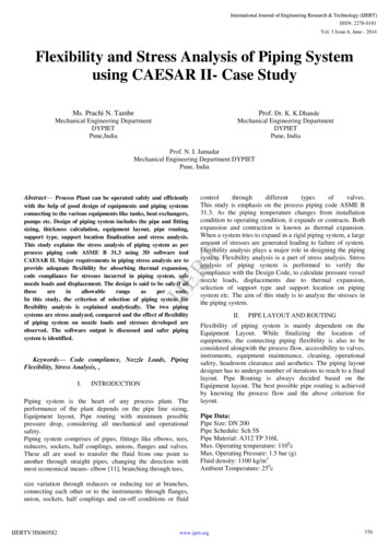
1 and 2--stage Long Line Applications -- Outdoor Unit Above Indoor UnitFig. 4 – Outdoor Unit Above Indoor UnitSSSSSSSSMaximum lengths and separation per Table 8 belowA hard shut--off TXV is required beyond 50ft (15.2 m) total length or 20ft (6.1m) vertical separation, other accessories perlengths and heights in Table 9 below.A crankcase heater must be installed on compressor if not factory--supplied.Hard Start Kit (start capacitor and relay) required for 1--stage units.Heat pump only – Heating piston must be changed as shown in Table 10.Heat pump only – Bi--flow liquid line solenoid must be installed within 2 ft (0.61 m) of outdoor unit with arrow pointing towardsoutdoor unit.Vapor line traps are not required.See Product Data for specific unit for accessory part numbers.Table 8 – Maximum Total Equivalent Length Outdoor Unit ABOVE Indoor UnitSize18243036,3742,4348,4954,60,61SystemTypeAC OnlyAC OnlyAC/HPAC OnlyAC OnlyAC/HPAC OnlyAC OnlyAC/HPAC OnlyAC/HPAC /81/45/163/81/45/163/85/163/85/163/83/83/8Vertical Separation ft (m) Outdoor unit ABOVE indoor unit25(7.6)26---50(7.9--- 15.2)51---75(15.5---22.9)76--- *250*250*250*250*250*125250*250*--- 0*250*--- 50*250*--- 250*250*--- 250*250*--- 250*250*--- 250*250*--- --250*250*250*250*250*250*250*250**Maximum Actual Length Not to Exceed 200ft (61 m)Table 9 – 1 and 2--Stage AC/HP with Puronr Refrigerant Long Line Description ft (m)Beyond these lengths, long line accessories are requiredAC1 & 2---StgAC Liquid Line Size1/4 TXV5/16 TXV3/8 TXVOutdoor Above Indoor175 (53.3)120 (36.6)80 (24.4)HP1 & 2---StgAC Liquid Line Size3/8 TXVOutdoor Above Indoor80 (24.4)Table 10 – Heat Pump Outdoor Piston Change -- Outdoor Unit ABOVE Indoor -7.6) 1 1 1 1 1 1 126--- 50(7.9---15.2) 1 1 2 2 2 2 2Vertical Separation ft (m) --- Outdoor Above Indoor Unit51---7576 ---100101 ---125126--- 150(15.5---22.9)(23.2--- 30.5)(30.8 ---38.1)(38.4--- 45.7) 2 3 3 4 2 3 4 5 2 4 5 6 2 4 5 6 3 4 5 7 3 4 5 7 3 5 6 88151---175(46.0---53.3) 5 6 8 8 8 9 10176--- 200(53.6--- 61.0) 6 7 9 9 10 10 12
Variable Speed Long Line ApplicationsLSV (25VNA0 & 280BNV Only)Max lengths shown belowSee Table 12for5 forLSV (25VNA0 & 280BNV Only)Maximum Height andLSV (25VNA0 &280BNV Only)Equivalent LengthSModels 25VNA0 and 280BNV only –Bi--flow liquid line solenoid must beinstalled within 2 ft (0.61 m) of outdoorunit with arrow pointing towardsoutdoor unit. Beyond 20ft (6.1m)vertical separation.SModels 25VNA0 and 280BNV only –Bi--flow liquid line solenoid must beinstalled within 2 ft (0.61 m) ofoutdoor unit with arrow pointingtowards outdoor unit. Beyond 20ft(6.1m) vertical separation.SVapor line should slope toward indoorunit for all variable speed applications.SSMax lengths depend on unit type. Seetables below.An inverted vapor--line trap must beinstalled at indoor unit. The top peakof trap must be greater than height ofindoor coil.SA hard shutoff TXV is required on theindoor unitfor all variable--speedapplicationsSA hard shutoff TXV is required on theindoor unit for all variable--speedapplicationsSNo other accessories requiredSMax lengths depend on unit type. Seetables below.SNo other accessories requiredSModels 25VNA0 and 280BNVonly – Bi--flow liquid linesolenoid must be installed within2 ft (0.61 m) of outdoor unit witharrow pointing towards outdoorunit. Beyond 80ft (24.4m)vertical separationSA hard shutoff TXV is requiredon the indoor unit for allvariable--speed applicationsSMax lengths depend on unit type.See tables below.SNo other accessories are requiredTable 11 – Maximum Tubing LengthsMaximum Vertical Separation ft. (m)ModelsMax Total / Equivalent Lengthft. (m)Outdoor AboveOutdoor Below25VNA0 / 280BNV250 / 200 (76.2 / 61.0)200 (76.2)See Table25VNA8 / 288BNV100 / 100 (30.5 /
AC with Puronr Refrigerant Long Line Description ft (m) Beyond these lengths, a TXV is required Total Length Outdoor Unit Above or Below Indoor Unit TXV required beyond 50 ft. (15.2 m) TXV required beyond 20 ft. (6.1 m) AC with Puronr Refrigerant Long Line Description ft (m) (Beyond these lengths, long line accessories are required)