Transcription
TRADE OFPipefittingPHASE 2Module 5Technical DrawingUNIT: 4Drawings for Pipe Installation
Produced byIn cooperation with subject matter expert:Finbar Smith SOLAS 2014
Module 5– Unit 4Drawings for Pipe InstallationTable of ContentsUnit Objective . 1Learning Outcome . 21.0System drawings (PFDs and P&IDs). 31.1 Process Flow Drawing (PFD) . 31.2 Process and Instrumentation Drawing (P&ID) . 42.0Drawing Practical . 62.1 Exercise No. 2.5.4a . 72.2 Exercise No. 2.5.4b. 82.3 Exercise No. 2.5.4c . 10Exercises . 12Additional Resources . 13Industrial Insulation Phase 2Revision 2.0 September 2014
Module 5– Unit 4Drawings for Pipe InstallationUnit ObjectiveThere are five units in Module 5. Unit 1 focuses on Drawing Methods &Types, Unit 2; Standard Drawing Conventions, Unit 3; Drawing Equipment &Practice, Unit 4; Drawings for Piping Installation, Unit 5; Traceability Record.In this unit you will be introduced to Drawings for Pipe Installation.Module 5TechnicalDrawingUnit 1Unit 2Unit 3Unit 4Unit 5DrawingMethods &TypesStandardDrawingConventionsDrawingEquipment &PracticeDrawings forPipingInstallationTraceabilityRecordIndustrial Insulation Phase 2Revision 2.0 September 20141
Module 5– Unit 4Drawings for Pipe InstallationLearning OutcomeBy the end of this unit each apprentice will be able to: Identify and draw Piping and Instrument Diagram (P&ID) symbolsfrequently used for valves instruments and equipment as per ExerciseNo. 2.5.4a Identify and draw isometric symbols used for piping systems i.e.screwed, butt welded as per Exercise No. 2.5.4b Identify and draw pipe General Arrangement (GA) symbols that areused for piping general arrangement drawings as per Exercise No.2.5.4c Sketch single line piping isometric for 2 of the piping assembly spools Dimension and label single line piping isometric drawings Sketch correct piping GA views for 2 of the piping assembly spoolsIndustrial Insulation Phase 2Revision 2.0 September 20142
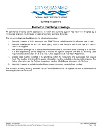
Module 5– Unit 4Drawings for Pipe Installation1.0 System drawings (PFDs andP&IDs)Key Learning Points Identify the function of a Process Flow Drawing (PFD) 1.1Identify the function of a Process and Instrumentation Drawing(P&ID)Process Flow Drawing (PFD)A process flow diagram (PFD) is a diagram commonly used in chemical andprocess engineering to indicate the general flow of plant processes andequipment. The PFD displays the relationship between major equipment of aplant facility and does not show minor details such as piping details anddesignations. Typically, process flow diagrams of a single unit process willinclude the following: Process piping Major equipment items Control valves and other major valves Connections with other systems Major bypass and recirculation streams Operational data (temperature, pressure, mass flow rate, density, etc.). Process stream namesProcess flow diagrams generally do not include: Pipe classes or piping line numbers Process control instrumentation (sensors and final elements) Minor bypass lines Isolation and shutoff valves Maintenance vents and drains Relief and safety valves FlangesIndustrial Insulation Phase 2Revision 2.0 September 20143
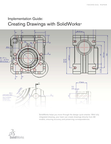
Module 5– Unit 4Drawings for Pipe InstallationProcess flow diagrams are high levels drawings usually of multiple processsystems within a large industrial plant and may be called block flow diagrams orschematic flow diagrams. Figure 1 illustrates a typical PFD for an evaporatorsystem.Figure 1 – PFD of Typical Evaporator system1.2Process and Instrumentation Drawing(P&ID)The P&ID shows the interconnection of process equipment and theinstrumentation used to control the process. In the process industry, astandard set of symbols is used to prepare P&ID drawings of processes as canbe seen in Figure 2 below. For processing facilities, a P&ID is a pictorialrepresentation of the following: Key piping and instrument details Relationship between control instruments and process equipment Control and shutdown schemes Safety and regulatory requirements Basic start up and operational informationIndustrial Insulation Phase 2Revision 2.0 September 20144
Module 5– Unit 4Drawings for Pipe InstallationFigure 2 – P&ID of Typical compressed air systemAs a rule P&IDs do not have a drawing scale and present only the relationshipor sequence between components. Just because two pieces of equipment aredrawn next to each other does not indicate that in the plant the equipment iseven in the same building; it is just the next part or piece of the system. Thesedrawings only present information on how a system functions, not the actualphysical relationships. Because P&IDs provide the most concise format forhow a system should function, they are used extensively in the operation,repair, and modification of the plant.Industrial Insulation Phase 2Revision 2.0 September 20145
Module 5– Unit 4Drawings for Pipe Installation2.0 Drawing PracticalKey Learning Points Identify and draw Piping and Instrument Diagram (P&ID) symbolsfrequently used for valves instruments and equipment Identify and draw isometric symbols used for screwed and buttwelded fittings for piping systems. Identify and draw pipe General Arrangement (GA) symbols that areused for piping general arrangement drawings Sketch single line piping isometric for 2 of the piping assemblyspools from Phase 2, Module 4, Unit 6. Dimension and label these single line piping isometric drawings Sketch correct piping GA views for 2 of the piping assembly spoolsfrom Phase 2, Module 4, Unit 6.Practical TaskThis is a practical task. Please refer to relevant sections of the coursenotes and your instructor for additional information and instruction.Industrial Insulation Phase 2Revision 2.0 September 20146
Module 5– Unit 42.1Drawings for Pipe InstallationExercise No. 2.5.4aIndustrial Insulation Phase 2Revision 2.0 September 20147
Module 5– Unit 42.2Drawings for Pipe InstallationExercise No. 2.5.4bIndustrial Insulation Phase 2Revision 2.0 September 20148
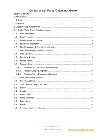
Module 5– Unit 4Drawings for Pipe InstallationFigure 3 – Common Isometric Pipe symbolsIndustrial Insulation Phase 2Revision 2.0 September 20149
Module 5– Unit 42.3Drawings for Pipe InstallationExercise No. 2.5.4cIndustrial Insulation Phase 2Revision 2.0 September 201410
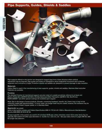
Module 5– Unit 4Drawings for Pipe InstallationFigure 4- Common GA Pipe symbolsIndustrial Insulation Phase 2Revision 2.0 September 201411
Module 5– Unit 4Drawings for Pipe InstallationExercises Identify and draw Piping and Instrument Diagram (P&ID) symbolsfrequently used for valves instruments and equipment as per ExerciseNo. 2.5.4a Identify and draw isometric symbols used for piping systems i.e.screwed, butt welded as per Exercise No. 2.5.4b Identify and draw pipe General Arrangement (GA) symbols that areused for piping general arrangement drawings as per Exercise No.2.5.4c Sketch single line piping isometric for 2 of the piping assembly spoolsfrom Phase 2, Module 4, Unit 6. Dimension and label these single line piping isometric drawings Sketch correct piping GA views for 2 of the piping assembly spoolsfrom Phase 2, Module 4, Unit 6.Industrial Insulation Phase 2Revision 2.0 September 201412
Module 5– Unit 4Drawings for Pipe InstallationAdditional ResourcesTitleAuthorRef. CodeThe Induction Book, “Code ofBehaviour & Health & Safety SOLASGuidelines”Basic Welding and FabricationW KenyonFundamentals of Fabrication andFJM SmithWelding EngineeringWorkshop processes, practicesBlack, Bruce Jand materials, 3rd edition, Elsevier 2004Science & TechnologyLawrence SmythNew Engineering Technology& Liam HennessyISBN 0-582-00536LISBN 0-582-09799-1ISBN-13:9780750660730ISBN 086 1674480Videos: Understanding welding fumes Welder on Site Be Aware (Vocam) Powered hand tool safety (Vocam) Industrial Ergonomics (Vocam)Available from:Vocam IrelandCircle Organisation LtdFriar Street, Thurles, Co Tipperary, IrelandTel: 353 504 24666Industrial Insulation Phase 2Revision 2.0 September 201413
Castleforbes HouseCastleforbes RoadDublin 1
used for piping general arrangement drawings as per Exercise No. 2.5.4c Sketch single line piping isometric for 2 of the piping assembly spools from Phase 2, Module 4, Unit 6. Dimension and label these single line piping isometric drawings Sketch correct piping GA v