Transcription
Seismic Engineering Knowledge TransferSeminarSeismic Design and Response of NPP PipingAlexey Berkovsky (bam@cvs.spb.su)CKTI-Vibroseism, St. Petersburg, Russiawww.cvs.spb.su21-25 November 2011Nuclear Research Institute Rez, Czech Republic
Overview– Terms and Definitions;– Piping Flexibility and Stress Analysis;– Seismic Design and Qualification;– ASME BPVC– Seismic Restraints– Sample of seismic analysis of NPP piping withuse of different types of seismic restraining2
Terms and Definitions(ASME B31E “Standard for the Seismic Design and Retrofit of Above-Ground Piping Systems”)active components: components that must perform an active function,involving moving parts or controls during or following theearthquake (e.g., valves, valve actuators, pumps, compressors, andfans that must operate during or following the design earthquake);axial seismic restraint: seismic restraint that acts along the pipe axis;critical piping: piping system that must remain leak tight or operable(see definitions) during or following the earthquake;design earthquake: the level of earthquake for which the pipingsystem is to be designed for to perform a seismic function (positionretention, leak tightness, or operability);ductile piping system: in the context of this Standard for seismicqualification, ductile piping system refers to a piping system wherethe piping, fitting, and components are made of material with aminimum elongation at rupture of 15% at the temperatureconcurrent with the seismic load;3
Terms and Definitionsfree-field seismic input: the ground seismic input at the facility location;in-structure seismic input: the seismic excitation within a building orstructure, at the elevation of the piping system attachments to thebuilding or structure;lateral seismic restraints: seismic restraints that act in a directionperpendicular to the pipe axis;leak tightness: the ability of a piping system to prevent leakage to theenvironment during or following the earthquake;noncritical piping: piping system other than critical piping thatnevertheless must meet the requirements for position retention;position retention: the ability of a piping system not to fall or collapse incase of design earthquake;4
Terms and Definitionsseismic design: the activities necessary to demonstrate that a pipingsystem can perform its intended function (position retention, leaktightness, operability, or a combination) in case of design earthquake;seismic function: a function to be specified by the engineering designeither as position retention, leak tightness, or operability;seismic interactions: spatial or system interactions with other structures,systems, or components that may affect the function of the pipingsystem;seismic response spectra: a plot or table of accelerations, velocities, ordisplacements versus frequencies or periods;seismic restraint: a device intended to limit seismic movement of thepiping system;seismic retrofit: the activities involved in evaluating the seismicadequacy of an existing piping system and identifying the changes orupgrades required for the piping system to perform its seismicfunction5
Terms and Definitionsseismic static coefficient: acceleration or force statically applied to thepiping system to simulate the effect of the earthquake;6
Piping Flexibility and Stress AnalysisSTRESS ANALYSIS: WHAT DOES IT MEAN?Piping Stress Analysis is a term applied tocalculations, which address the static anddynamic loading resulting from the effects ofgravity, temperature changes, internal andexternal pressures, changes in fluid flow rate andseismic activity. Codes and standards establishthe minimum requirements of stress analysis.7
Piping Flexibility and Stress AnalysisPurpose of piping stress analysis is to ensure: Safety of piping and piping components; Safety of connected equipment and supporting structure; Piping deflections are within the limits;Deflection limits are not Code requirements, but are generally acceptedpractices; a 13-mm (1/2-in.) deflection is a generally accepted guideline forgeneral process plant piping. More stringent limits may be required for linesthat must avoid pockets caused by sagging of the line; greater deflection isgenerally acceptable from a mechanical integrity standpoint, if not anoperator confidence standpoint.8
Piping Flexibility and Stress AnalysisHOW PIPING AND COMPONENTS FAIL (MODES OF FAILURES) FAILURE BY GENERAL YIELDING: Failure is due to excessive plasticdeformation:o Yielding at Sub Elevated temperature: Body undergoes plasticdeformation under slip action of grains;o Yielding at Elevated temperature: After slippage, material recrystallizes and hence yielding continues without increasing load.This phenomenon is known as creep FAILURE BY FRACTURE: Body fails without undergoing yieldingo Brittle fracture: Occurs in brittle materials.o Fatigue: Due to cyclic loading initially a small crack is developedwhich grows after each cycle and results in sudden failure.9
Piping Flexibility and Stress AnalysisWHEN PIPING AND COMPONENTS FAIL(THEORIES OF FAILURE):Maximum principal stress theoryThis theory states that yielding in a piping component occurs when themagnitude of any of the three mutually perpendicular principle stressesexceeds the yield point strength of the materialMaximum shear stress theoryThis theory states that failure of a piping component occurs when the maximumshear stress exceeds the shear stress at the yield point in a tensile test. In thetensile test, at yield, S1 Sy (yield stress), S2 S3 0.So yielding in thecomponents occurs when:Maximum Shear stress max S1 - S2 / 2 Sy / 2Different Codes – different theories of failure!10
Piping Flexibility and Stress AnalysisCLASSCIFICATION OF LOADS PRIMARY LOADS: These loads are typical loads such as internalpressure, external pressure, gravitational forces like the weight of pipeand fluid. These loads are generally called as sustained loads. Failure ofthe pipe due to any of the mentioned loads are called as catastrophicfailuresThese can be divided into two categories based on the duration of loading.oSustained loadsThese loads are expected to be present through out the plantoperation. e,g. pressure and weight.oOccasional loads.These loads are present at infrequent intervals during plantoperation. e,g. earthquake, wind, etc.11
Piping Flexibility and Stress AnalysisCLASSCIFICATION OF LOADS SECONDARY LOADS: Just as primary loads have origin in some force,secondary loads are caused by displacement of some kind. e.g. the pipemay be under load if the tank nozzle moves up or down. A pipesubjected to a cycle of hot and cold fluid similarly undergoes cyclic loadsand deformation.oExpansion loads: These are loads due to displacements of piping. e,g.thermal expansion, seismic anchor movements, and building settlement.12
Piping Flexibility and Stress AnalysisSTRESS CATEGORIES PRIMARY STRESSES:These are developed by the imposed loading and are necessary to satisfy theequilibrium between external and internal forces and moments of the pipingsystem. Primary stresses are not self-limiting. SECONDARY STRESSES:These are developed by the constraint of displacements of a structure. Thesedisplacements can be caused either by thermal expansion or by outwardlyimposed restraint and anchor point movements. Secondary stresses are selflimiting. PEAK STRESSES:Unlike loading condition of secondary stress which cause distortion, peakstresses cause no significant distortion. Peak stresses are the highest stressesin the region under consideration and are responsible for causing fatiguefailure.13
Piping Flexibility and Stress AnalysisLOAD-CONTROLLED VERSUS DEFORMATIONCONTROLLED BEHAVIOR14
Piping Flexibility and Stress AnalysisPIPING CODES & STANDARDSINDUSTRIAL PIPING: ASME CODES (B31.X): B31.1 Power Piping (Non nuclear) B31.2 Fuel Gas Piping B31.3 Chemical Plant and Refinery piping B31.4 Liquid Petroleum piping B31.5 Refrigeration piping B31.7 Nuclear Piping (Superseded by ASME Section III) B31.8 Gas Transmission Piping B31.9 Building Service Piping B31.10 Cryogenic Piping B31.11 Slurry Piping EUROPEAN PIPING STANDARD:EN 13480 (2002) European Standard for Metallic Industrial Piping RUSSIAN BOILER CODE:РД 10-249-98 «Нормы расчета на прочность стационарных котлов и трубопроводов15пара и горячей воды»
Piping Flexibility and Stress AnalysisPIPING CODES & STANDARDSNUCLEAR PIPING: ASME B&PV CODE, SECTION III (NB, NC, ND) GERMAN KTA STANDARD RUSSIAN PNAE STANDARD BRITISH BS STANDARD FRENCH RCCM JAPAN JSME&JEAG CANADA CSA/CAN SWEDEN SKIFS EUROPEAN PRESSURE EQUIPMENT DIRECTIVE16
Piping Flexibility and Stress AnalysisTYPES OF DESIGN PERMITTED BY THE ASME BPV CODESECTION III Design By Analysis (NB and NC 3200): “Design byanalysis” is based on the maximum shear stress theory.In general, linear elastic methods, rules for stresscategorization, and appropriate limits are used to evaluatethe design loading conditions on a containment vessel.This method also requires a fatigue analysis and fracturemechanics evaluations (prevention of non-ductile failure).“Design by analysis” allows plastic analysis, elasticplastic analysis, and experimental stress analysis.“Design by analysis” requires a higher degree ofengineering than “design by rule” since all aspects ofloading must be considered and evaluated17
Piping Flexibility and Stress AnalysisTYPES OF DESIGN PERMITTED BY THE ASME BPV CODESECTION III Design by Rule (or Design by Formula) (NB/NC 3600): “Design byrule” is based on a set of simple formulas to determine either theminimum thickness or the maximum allowable working pressure forpressure load conditions. The equations provided in the ASMEBPVC are based on the maximum stress theory. The "design by rule"method provides a quick, simple, and nationally recognized methodfor the design and construction of piping and vessels for pressureservice. This reduces engineering costs for vessel designIt should be noted that in Design by Analysis the stresses consideredare Stress Intensities, Sm rather than directional Sl or Sh (longitudinalor hoop) or 1, 2 or 3, principal stresses.18
Piping Flexibility and Stress AnalysisSTRESS INTENSITIESStress intensities for Class 1 components and piping aredetermined using Tresca criteria as the largest of thefollowing: 1 2Sm max 2 3 3 1where 1 and 2 are the principal stresses in or parallel tothe mid plane of the shell, wall or plate of the componentand 3 is the principal stress perpendicular to the midplane of the shell, wall or plate of the component.19
Piping Flexibility and Stress AnalysisSTRESS INTENSITIESWhere 1, 2 and 3 stresses are tensile they are takenas a positive and where they are compressive in naturethey are taken as a negative value hence, result in anincreased stress intensity.The allowable stress Sm for Design by Analysis is takenas the lesser of ultimate tensile stress for the material inquestion at temperature from the Tables in ASMEB&PVC Section II Part D divided by 3 or 2/3 times yieldstress at temperature also from ASME B&PVC Section IIPart D.20
Piping Flexibility and Stress AnalysisSUBSECTIONS OF ASME BPVC FOR PIPINGANALYSIS NB-3600 - Design and analysis for Class 1 pipes. This subsectioncovers 1 Class pipes working under primary loop pressure. NC-3600 - Design and analysis for Class 2 pipes. This Classincludes the safety-related systems that do not attached in the 1 Classand are working, for example, in accident cooling of protectionsystems, steam and feedwater pipes, etc. ND-3600 - Design and analysis for Class 3 pipes. For example, asystem of technical water should be included in this Class. The special requirements for piping supports design and strengthanalysis are contained in the ASME BPVC Subsection NF-360021“Design Rules for Piping Supports”.
Piping Flexibility and Stress AnalysisSUBSECTIONS OF ASME BPVC FORPIPING ANALYSISMore detailed recommendations and requirements concerned seismicanalysis of safety-related NPP piping systems are given in thefollowing Appendixes: Appendix N “Dynamic Analysis Methods”; Appendix F “Rules for Evaluation of Service Loading with Level DService Limits”.Additionally for the main parts of ASME BPVC there is an actuallyissuing by NRC the special documents, such as RG and SRP. Thesedocuments provide specification of requirements for equipmentclassification, combination of loads and describe a new analysismethods.Up to now NRC issued more than 35 RG and SRP regarding piping22systems.
Seismic Design and QualificationSeismic Specification:(a) The scope and boundaries of systems to be seismicallydesigned;(b) The applicable design and construction code;(c) The required seismic function of the piping system (positionretention, leak tightness, or operability);(d) The free field seismic input for the design basis earthquake;(e) the in-structure seismic response spectra;(f) The operating and design conditions concurrent with theseismic load23
Seismic Design and QualificationSeismic Qualification:The seismic qualification requirements differ depending on theseismic function of the piping system: operability, leak tightness,or position retention.Operability: the ability of a piping system to deliver, control(throttle), or shut off flow during or after the design earthquake.The seismic qualification of piping systems that must remainoperable during or following the design basis earthquake must beestablished by static or dynamic analysis or by testing. Theseismic qualification of piping systems for operability mustdemonstrate the seismic adequacy of the piping itself, the pipesupports and their attachment to the building structure, and theequipment and components within the scope of seismicqualification.24
Seismic Design and QualificationSeismic Qualification:Leak Tightness: the ability of a piping system to prevent leakageto the environment during or following the earthquakeThe requirements for seismic qualification of piping systems thatmust remain leak tight during or following the earthquake varywith pipe size and the magnitude of seismic input For pipe largerthan 2" nominal pipe size (NPS) and for a earthquake with a peakspectral acceleration larger than 0.3g, it is recommended that theseismic design and retrofit requirements for leak tightness beidentical to the operability requirements, except for theoperability requirements of active equipment, which are notapplicable. For piping 2" NFS and smaller, or where the PSA isbelow 0.3g, the position retention rules may apply for leaktightness, with the additional requirement that the loads imposedon nonwelded and non-flanged pipe joints (for example swagefittings, groove couplings, etc.) be within vendor limits.25
Seismic Design and QualificationSeismic Qualification:Position retention: the ability of a piping system not to fall orcollapse in case of earthquake;The seismic qualification of piping systems that must retain theirposition, but need not be leak tight or perform a function, may beestablished by sway bracing following standard support andrestraint spacing criteria. Also the seismic adequacy of the pipesupports and their attachment to the building structure should beestablished. The seismic load on each pipe support should becalculated by seismic analysis, and the seismic adequacy ofsupports and anchorage for position retention should bedemonstrated against failure modes that could cause loss ofposition. The permanent deformation of supports is acceptable inthis case, provided it does not cause the pipe to disengage and falloff.26
Seismic Design and QualificationSeismic Qualification Criteria:OperabilityLeak Tight(NPS 2”PSA 0.3g)Leak Tight(NPS 2”PSA 0.3g)PositionRetentionPipe StressYesYesNosway esYesYesYesInteractionsYesYesYesYesCriterion27
Seismic Design and QualificationMaterial Condition:The seismic retrofit of existing piping systems should take intoaccount the material condition of the system. Where corrosion orenvironmental cracking are suspected, the piping should beinspected by non-destructive volumetric techniques. The qualityof construction and the maintenance condition of the systemshould be inspected in the field, and the maintenance record ofequipment and components should be investigated with thefacility engineer to assess their adequacy, operability andstructural integrity.28
Seismic Design and QualificationInteractions:An interaction is the seismic induced failure of a structure, systemor component, other than the piping systems being qualified, thataffects the function of the piping system. An interaction source isthe component or structure that could fail and interact with atarget. An interaction target is a component that is beingimpacted, sprayed or accidentally activated. A credible interactionis one that can take place. A significant interaction is one that canresult in damage to the target. There are four types of seismicinteractions:29
Seismic Design and QualificationInteractions:Falling - A falling interaction is an impact on a criticalcomponent due to the fall of overhead or adjacent equipment orstructure.Swing - A swing or sway interaction is an impact due to theswing or rocking of adjacent component or suspended system.Spray - A spray interaction is spray or flooding due to the leakageor rupture of overhead or adjacent piping or vessels.System - A system interaction is an accidental or erroneous signalresulting in unanticipated operating conditions, such as theunintended start-up of a pump or closure of a valve.30
Seismic Design and QualificationDocumentation:The designer should prepare a Qualification Report, certified by aProfessional Engineer experienced in the field of piping systems designand construction, and in seismic qualification. The Qualification Reportshould include, as a minimum:(a) Drawing, sketches and (for existing systems) photographs, showingthe scope of work;(b) Final pipe support arrangement;(c) Calculations showing design input (acceleration, static force, orresponse spectra) and code compliance for piping, equipment, andsupports;(d) Documentation of qualification of equipment operability whereapplicable;(e) Drawings for new or modified supports, with dimensions, weld andanchor bolt details, bill of materials, and information necessary formaterial procurement and construction.31
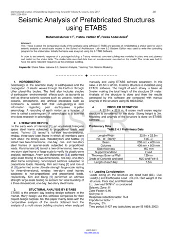
Seismic Design and QualificationSeismic Input:- design ground response spectra;- in-structure response spectra;- acceleration time histories (accelerograms);- seismic anchor movements32
Seismic Design and QualificationSeismic InputFloor (In-Structure) Response 0.6-0.600510152025303540Frequency, Hz Enveloped and Broadened 15 %, Set of Spectra for different dampingAcceleration, g0550.410X-Direction15202530202530202530Time, Sec0.20-0.2-0.40.6-0.60Acceleration, gAcceleration, m/sec2Acceleration, g3050.410Y-Direction15Time, Sec0.20-0.2-0.4-0.6Seismic Anchor Movement0510Z-Direction15Time, Sec Cross-Correlation of the Spatial Components Comparison of Calculated and Target Spectra; Duration of intensive part33
Seismic Design and QualificationAcceptance Criteria for the developing of artificialacceleration time histories1. Enveloping of target spectra: the response spectra of thegenerated time histories should envelop the floor response spectra.Specifically, less than 5 points (no more than 10 %) shall fall belowthe target spectra.2. The response spectra of the generated artificial time history shouldenvelop the design response spectra for all damping values usedin the analyses,3. Frequency intervals at which the spectral values are calculatedshould be detailed enough. Generally frequency spacing shouldcomply to the values presented in the Table below :34
Seismic Design and QualificationAcceptance Criteria for the developing of artificialacceleration time historiesFrequency intervals for calculation of response spectrumFrequency range (Hz)0,2 - 33,- 3,63,6 - 55-88 - 1515 - 1818 - 2222 - 40Increment (Hz)0,100,150,200,250,5012335
Seismic Design and QualificationAcceptance Criteria for the developing of artificialacceleration time histories4. To be considered statistically independent, the directionalcorrelation coefficients between pairs of records shall not exceed avalue of 0.305. The resultant time history should be long enough so that furtherincreases in its length will not produce significantly different responsespectra.6. Strong motion durations should be not less than 10 sec.7. The artificial time histories shall be baseline corrected8. The time history shall have a sufficiently small time increment36
Seismic Design and QualificationAcceptance Criteria for the developing of artificialacceleration time historiesReferences: European utility requirements for LWR Nuclear Power, Volume 2"Generic Nuclear Island Requirements", Appendix A "Method of SeismicAnalysis" ASCE/SEI 43-05, Seismic Design Criteria for Structures, Systems, andComponents in Nuclear Facilities ASME BPVC, Appendix N "Dynamic Analysis Methods" ASCE 4-98. "Seismic Analysis of Safety-Related Nuclear Structuresand Commentary." NUREG-0800. “Standard Review Plan. Paragraph 3.7.1. SeismicDesign Parameters.” IEEE Std 344-2004. ”IEEE Recommended Practice for SeismicQualification of Class 1E Equipment for Nuclear Power GeneratingStations37
Seismic Design and QualificationLoad CombinationPiping:P D L ESPiping Supports, Equipment Nozzles:D L ES ESAM TEP – Internal Pressure, D – Dead Weight,L – Live Weight, ES – Seismic Inertial Load,ESAM – Loads from Seismic Anchor Movement,TE – Operational Load (Thermal Expansions)38
Seismic Design and QualificationConditions that caused piping failures (Rules of Thumb): Unacceptable anchor motion; Rigidly tied branch lines and flexible header; Poor Horizontal restraining; Too long valve operators; Poor Material conditions; Poor Construction quality; Undersized pipe support members; Significant Interactions39
Seismic Design and Qualification(ASME B31E “Standard for the Seismic Design and Retrofitof Above-Ground Piping Systems”)40
Seismic Design and Qualification(ASME B31E “Standard for the Seismic Design and Retrofitof Above-Ground Piping Systems”)41
Seismic Design and QualificationSeismic QualificationList of SystemsSeismic InputLoad CombinationFE ModelsAnalysisNoSeismicUpgradingIs pipingseismicallyadequate?Codes tem verifed42
Peculiarities of piping systems modeling for seismic analysis:Density of FE model:Lmin1 E*I *g *42 2 * FMAXwFMAX–"Upper" natural frequency of the systemE–Elastic ModulusI–Moment of Inertiag–Gravity accelerationw–Weight per lengthDecoupling Criteria (Standard Review Plan 3.7.2 “Seismic System Analysis”)
Service Limits ASME BPVC establishes four Levels of Service Limits Loading for eachcomponent or support. These Service Limits may be designated in theDesign Specification and defined as different Levels (Levels A, B, C and D).The NCA-2142.4 gives the following definition of these Service Limits:Level D Service Limit. Level D Service limits are those sets of limits whichmust be satisfied for all Level D Service loading identified in the DesignSpecification for which these Service Limits are designated. These sets oflimits permit gross general deformations with some consequent loss ofdimensional stability and damage requiring repair, which may requireremoval of the component from service. Therefore the selection of this limitsshall be reviewed by the Owner for compatibility with established systemsafety criteria (NCA-2141).
Definition of Seismic Loads The ASME BPVC has a several subsections especially oriented forseismic analysis and design. Among them one of the most importantis the Appendix N “Dynamic Analysis Methods”, which contains thearticle “Seismic analysis”. In this article there are the followingitems: N-1210 - “Earthquake description“. This article contains the detaileddescription and recommendations about applied input seismicexcitation in terms of the Response Spectrum and Time History aswell. N-1220 - “Methods of dynamic analysis“. This chapter gives a fullrange of dynamic modeling and analysis technique description suchlike THA and Response Spectrum Method. N-1230 - "Damping”. The recommended damping values fordifferent types of constructions are presented in this article. Also thevarious methods of incorporating the damping in structural dynamicsare given.
DAMPING VALUES FOR PIPES ACCORDING TOASME BPVCASME BPVC provides the different values of damping which are depended fromthe seismic excitation level and pipe output diameter. In the Japan JEAG 4601 thedamping values depends on type of piping, number of supports and insulationparameter and vary from 0,5 to 2,5%.Table demonstrates ASME BPVC values and contains the damping ratio valuesrecommended for seismic analysis.Application of the Case N-411-1 may significantly reduce the seismic response up to30-35 % in comparison with values originally used in ASME BPVC.PipeLevel BLevel DCase N-411-1OBESSE0 - 10 Hz10 - 20 Hz 20 HzD 305mm0.020.030.050.05 - 0.020.02D 305mm0.010.020.050.05 - 0.020.02
ASME BPVC, NB-3650, Equation (9)Resulting Moment from static and dynamic loadsM i M xi2 M yi2 M zi2For the tee elements the Equation (9) is written in thefollowing form (NB-3683.1)S SSwhere:PDoMbMr B1 B2b B2 r2TrZbZrTr - nominal wall thickness of designated RUN pipe;Mr, Mb - resulting internal moments in the run and branch pipesrespectively;Zr,Zb - approximate section modulus of designated run and attachedbranch pipes respectively.
Stress indices B1 and B2(defined by the table NB-3681(a)-1)For straight pipes: B1 0.5 and B2 1.0;For curved pipes: B1 -0.1 0.4h , if 0.0 B1 0.5,B2 1.30 h23ifB2 1.0;For tee elements B2b and B2r are defined in accordance withNB-3683.8 and NB-3683.9 /3/.
ASME BPVC (NB/NC/ND-3600)The conditions of eq. (9) of NB-3652 shall be met using Service Level Dcoincident pressure P and moment Mi, which results in the maximumcalculated stress. The allowable stress to be used for this condition is 3.0Sm, but not greater than 2.0 Sy.49
ASME BPVC (NB/NC/ND-3600)50
ASME BPVC (NB/NC/ND-3600)An alternative to NB-3656(a): piping fabricated from ductile material (P-1 – P-9) D/tn 40 The sustained stresses due to weight are limited: The stress due to weight and inertial loading due to reversing dynamicloads: Seismic anchor motion:51
PIPING ANALYSIS SOFTWARE ME-21,ADLPIPE,NUPIPE,PIPESTRESS,SYSPIPECAESARII, AUTOPIPE,TRIFLEX,SIMFLEX,CAEPIPE,dPIPE
Seismic Restraints1. Sway Braces2. Snubbers2а. Hydraulic2б. Mechanical
Seismic Restraints3. Axial dampers (absorbers)3а. Hydraulic3б. Elastic-plastic4. Viscous Dampers
General requirements for seismic restraints Damping ability for any dynamic effects (vibration, shock,seismic, etc.); Long service life without maintenance; Resistance to the heat and radiation; A small reaction force acting on the piping during thermalexpansion; The absence of lag response under dynamic loading; The ability for overload without loss of functionality andmechanical properties; Ability to control performance; The low cost of manufacture and operation
Description of High Viscous DamperHigh damping in the device is a result of deformation of anextremely high viscous liquid that is located in the spacebetween damper’s piston and housing.
Description of High Viscous DamperVES TYPETEMPERATURE DEPENDENTDAMPERVD TYPELOW TEMPERATUREDEPENDANT VARIABLEDAMPING DAMPER
Installation of Dampers
Installation of Dampers
Installation of Dampers
Modeling of seismic restraints1. Sway Braces and Snubbers Axial stiffness Inactive under Normal Operation(Snubbers)2. Hydraulic Axial dampers (absorbers) Axial load reaction delay the nonlinear dependence of force fromthe loading rate3. Elasto-plastic axial dampers (absorbers) Axial load Initial gap Elasto-plastic model4. High Viscous Damper 3D loads Maxwell model
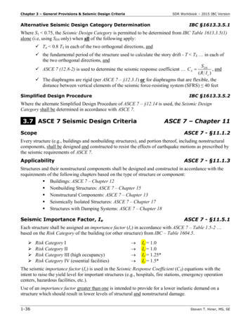
Mathematical Model of HVDSpecific peculiarity of HVD is significant dependence of damping and stiffnesscharacteristics against frequency of excitation:20000Elastic Stiffness, kN/mViscous Stiffness, kN/mEquivalent Stiffness, kN/mStiffness, kN/m15000100005000005101520Frequency, Hz25303540
Mathematical Model of HVDFeatures of Maxwell Model for HVD : the reaction of HVD at the low frequencyloading range is considered as a viscous andmay be described by an expression: R -B*v,where R – reaction force, v –velocity of apiston relatively to the housing, B – dampingresistance; for the high frequency range the damper'sreaction shows essentially elastic character andmay be described as: R -K*x, where x –relative displacement "piston-hosing", K –stiffness ratioKB
Mathematical Model of HVD 0 K/B - characteristic frequencyR x0*Ce*sin( *t) x0*Cv*cos( *t)R x0*Cs*sin( *t ); tg( ) Cv/Ce; Cs (Ce2 Cv2)1/2Ce K*( / 0)2/(1 ( / 0)2); Ce K*( / 0) /(1 ( / 0)2)Phase AngleMaxwell Model Characteristics
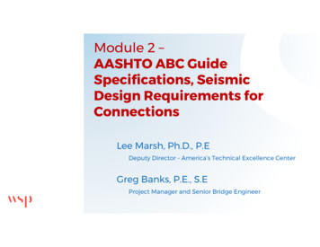
Mathematical Model of HVD4-parametrical Maxwell Model:Ce K1*( / 1)2/(1 ( / 1)2) K2*( / 2)2/(1 ( / 2)2)Cv K1*( / 1)/(1 ( / 1)2) K2*( / 2)/(1 ( / 2)2) 1 K1/B1 2 K2/B2characteristic frequencies for first and secondMaxwell chains
Mathematical Model of HVD4-parametrical Maxwell Model:approximationexperimental data
Simplified Model of HVD 4-parametrical Maxwell model is suitable for realization in theframe of the Time History Analysis (THA);Maxwell model of HVD is realized only in a few softwarepackages: ROHR2 and dPIPE;most commercially available piping software packages still usefor dynamic restraints only "snubber" model;the benefits of
ASME CODES (B31.X): B31.1 Power Piping (Non nuclear) B31.2 Fuel Gas Piping B31.3 Chemical Plant and Refinery piping B31.4 Liquid Petroleum piping B31.5 Refrigeration piping B31.7 Nuclear Piping (Superseded by ASME Section III) B31.8 Gas Transmission Piping B31.9 Building Service Piping B31.10 Cryogenic Piping