Transcription
MAIN DOCUMENT: ENGINEERING SPECIFICATION FOR PIPINGATTACHMENT NO.: 01SECTION: ENGINEERING STANDARD PIPING DESIGNNATIONAL FERTILIZERS LTD.,VIJAIPUR, GUNANFVP/M/AMM-II/CONT-55/66/2018-19ENGINEERING STANDARD PIPING DESIGNPage 1 of 16ES-6001
MAIN DOCUMENT: ENGINEERING SPECIFICATION FOR PIPINGATTACHMENT NO.: 01SECTION: ENGINEERING STANDARD PIPING DESIGNNATIONAL FERTILIZERS LTD.,VIJAIPUR, GUNANFVP/M/AMM-II/CONT-55/66/2018-19LIST OF l Design3.1.13.1.23.1.33.1.43.1.53.2Piping Arrangement3.2.13.2.23.3Pipe Fittings and BendsValvesPipe blinds (Ring and Disc)Relief ValvesAutomatic Control ValvesDouble Block ValvesSteam TrapsStrainers and FiltersThermal Expansion of PipingGuidelines for Equipments3.4.13.4.23.4.33.4.43.5Underground PipingGeneral Guide lines for routing of pipe lines.Guidelines for different piping 3.4ClearancesClearance between pipingSizes allowedMaterialCorrosion allowance on wall thicknessPumpsCompressorsTurbines and Steam Driven EquipmentsHeat ExchangerAuxiliary nsFlushing ConnectionSample ConnectionsOrifice PlatesConnection to Drinking Water3.6Supports, Anchors and Guides3.7Service Connections and Utilities3.8Safety Showers and Eye BathsPage 2 of 16ES-6001
MAIN DOCUMENT: ENGINEERING SPECIFICATION FOR PIPINGATTACHMENT NO.: 01SECTION: ENGINEERING STANDARD PIPING DESIGNNATIONAL FERTILIZERS LTD.,VIJAIPUR, GUNA3.9NFVP/M/AMM-II/CONT-55/66/2018-19Steam Tracing3.10 Special requirements for Toxic, Hydrocarbon and Flammable Fluid.Page 3 of 16ES-6001
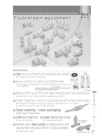
MAIN DOCUMENT: ENGINEERING SPECIFICATION FOR PIPINGATTACHMENT NO.: 01SECTION: ENGINEERING STANDARD PIPING DESIGNNATIONAL FERTILIZERS LTD.,VIJAIPUR, E1.1This specification covers general design requirements with respect to layoutand details for piping design.1.2Addendum SpecificationThis specification may be supplemented by special requirements for aparticular job, in which event the later shall take precedence in case of aconflict.SPECIFICATIONS2.0Criteria for design, fabrication and erection of non IBR piping systems shall bein accordance with ASME B 31.3 Process Piping Code latest edition and thosefor IBR piping shall be in accordance with Indian Boiler Regulations.REFERENCE STANDARDSASME B 31.3 - Process Piping CodeIBR - Indian Boiler RegulationsPDIL Engineering standardsES 6002-- General Piping SpecificationES 6012--ES 6029-- Steam trap InstallationSaf e t y Valve Installation and pipingPDS: P ( V 004) -- Dimension of Control Valve manifoldP 032-- Pipe trenchP 123-- Vent, drain, steam trap and Instrument tappingassembliesPS 01-- Pipe support - Standard type and applicationsPS 02-- Pipe spacingST 202--3.0DESIGN3.1General Design3.1.1Clearancesa)Details of sump for installation of Gate ValveWalkways and PlatformsThe minimum clear headroom over main walkways, passageways and workingareas at grade or floor elevations shall be 2.20 m. The minimum clearance oversecondary walkways, elevated platforms, passage ways and working areas shallbe 2.0 m. The minimum width for main walkways shall be 1.2 m. The minimumPage 4 of 16
MAIN DOCUMENT: ENGINEERING SPECIFICATION FOR PIPINGATTACHMENT NO.: 01SECTION: ENGINEERING STANDARD PIPING DESIGNNATIONAL FERTILIZERS LTD.,VIJAIPUR, GUNANFVP/M/AMM-II/CONT-55/66/2018-19ES-6001width for secondary walks and minor access points shall be 0.75 m.minimum width for catwalks shall be 0.6 m. (Ref./Fig.1).b)TheRoads and Rail RoadsThe minimum clear head room over rail roads shall be 6.0 m measured from thetop of track. The minimum clearance over primary roadways shall be 7.5 m.Secondary roads may have lower clearance, but not less than 5.0 m. Minimumclear head room over areas designated as main access ways or tracking areas(other than roads) shall be 3.7 m.c)EquipmentClearance should be available for maintenance and removal ofequipment without disturbing other equipment. Dismantling of sections of pipe ispermissible, if required for removal of equipment, when not operating. Piping toequipment shall be designed to permit ready removal of equipment without furtherpipe supports being required, Particular attention should be paid to layout of cableracks, instrument piping, etc. to ensure this.In areas where entry of handling equipment (e.g. Forklift truck or 5t Crane) isrequired for maintenance or handling of pumps and other machinery not otherwiseaccessible, the minimum clear head room for piping under which the handlingequipments are required to move shall be 4.5 m.Manholes and other access openings shall have a minimum clearance of 0.75meter in front of face of vessel or equipment flange (not cover plate where largerclearance may be required), and a minimum of 0.30 m from edges of flanges tonearest pipe or construction.d)Minimum Clearance for Piping Above GradeUsually bottom most part of any line is provided with a drain line. To facilitateproper draining (may be to a catch pot, in some cases) and proper supportingarrangement of the pipe the bottom of pipe should normally be kept at a minimumelevation of 400 mm from finished floor level. Where this is not possible elevationmay be lowered to even 150 mm giving due care to proper draining andsupporting of pipes. This does not apply to drain pipes. Insulation and valvesshould be taken in consideration while determining this clearance. In case ofcontrol valves, the minimum clearance shall be as per PDS: V 004.Page 5 of 16
MAIN DOCUMENT: ENGINEERING SPECIFICATION FOR PIPINGATTACHMENT NO.: 01SECTION: ENGINEERING STANDARD PIPING DESIGNNATIONAL FERTILIZERS LTD.,VIJAIPUR, earance Between PipingIn consideration of maintenance, the flange, or heat insulation, etc. theclearance between pipe surfaces should be sufficient but minimum for them.The clearances are shown in PDS: PS 02. The clearance indicated in PDS:PS02 are minimum and shall have to be increased where large lateral thermalmovements are involved, particularly where high temperature pipes are takinga 90O turn. Vertical pipe lines through floors shall be combined to reduce theopening size in floors.3.1.3Sizes AllowedIn general, no piping less than ½ // shall be used except for instrument piping.1 ¼ //, 3 ½ // and 5// pipe sizes normally should not be used. Where such sizesare used, valves should be of 1//, 3// and 4// respectively.3.1.4MaterialPiping material shall be selected in accordance with respective piping class.Reference may be made to General Piping Specification - Piping Element datasheet for selection of appropriate piping classification number for the specifiedservice conditions. Where system of higher service rating tie into systems oflower rating, an isolation valve shall be provided and the higher service ratingspecification shall be continued including the isolation valve.3.1.5Corrosion Allowance on Wall ThicknessThe minimum corrosion allowance for piping shall be as follows:Cast iron and carbon steel piping -- 1mmCorrosion resistant materials, including Aluminum, alloy steel, high nickel alloysand copper -- Nil3.2Piping Arrangement3.2.1Under Ground Piping3.2.1.1Buried PipesIn general, pipes should not be buried unless a specific advantage likeprotection freezing, fire or accidental damage or easy drainage by gravity flowetc. are gained. Traditionally the following lines may be buried:3.2.1.2(a)Cooling water distribution headers.(b)Fire Water mains(c)Sewage Lines(d)Drain lines (where gravity flow requirement necessitates the lines to beburied).Piping in Trenches(a)All piping requiring inspection and servicing or being provided withPage 6 of 16
MAIN DOCUMENT: ENGINEERING SPECIFICATION FOR PIPINGATTACHMENT NO.: 01SECTION: ENGINEERING STANDARD PIPING DESIGNNATIONAL FERTILIZERS LTD.,VIJAIPUR, ive heating and located below grade shall be in trenches.(b)Pipe trenches shall be sufficiently large to allow for repair of lines andshall be provided with removable covers. Typical trenches details havebeen indicated in PDS: P 032. Sump for valves and trenches shall be asper PDS: ST 202 & ST 203.Underground piping shall be done as per ES 6018. However, some ofgeneral precautions to be taken are as follows:3.2.2I.Provide casing pipe made of reinforced concrete or Carbon Steelto protect underground pipes passing under roads or access ways.II.Wherever electrical cables are coming on the way of pipes, pipeswill be taken below the cables.III.Wherever valves are to be provided, valve chamber of suitablesize should be constructed of brick or concrete.IV.Pipes shall clear the fouling with trench foundations and layout oftrench will be such as not to interfere with construction access.V.Trenches shall be provided with proper slope and suitable drainingscheme.General Guide Lines for Routing of Pipe Lines(a)Pipe lines shall be installed neatly so as to be as short and direct aspossible, with a minimum of directional changes. The flexibility shall beconsidered while deciding the routing of hot pipe lines.(b)Dead legs and pockets shall be avoided. This is important in case ofpipe line containing slurries or suspensions, fluids of high crystallizationpoint, corrosive fluids etc.(c)Overflow lines, drain lines, barometric lines from condensers etc. shouldbe as steep as possible. Barometric lines should preferably be installedvertical, if this is not possible, one of the two alternatives indicated inFig.2 can be adopted.(d)All piping within battery limits shall be elevated to provide minimum clearhead room as indicated in section 3.1 unless process considerationindicates otherwise, e.g. in pump suction lines.(e)Main service pipes, such as HP and LP steam condensate, fuel oil,town’s water, cooling water, town’s gas, compressed air etc. will oftenmost conveniently follow the road network and the piping layout thus islargely settled by general site conditions. However, use of 45O bendsand cross over is permitted for economy reasons, where it does notimpair the appearance of the plant.Page 7 of 16
MAIN DOCUMENT: ENGINEERING SPECIFICATION FOR PIPINGATTACHMENT NO.: 01SECTION: ENGINEERING STANDARD PIPING DESIGNNATIONAL FERTILIZERS LTD.,VIJAIPUR, GUNANFVP/M/AMM-II/CONT-55/66/2018-19ES-6001(f)All piping shall be grouped in banks whenever practicable.(g)All overhead piping shall be run at specific elevation established inadvance for piping in any one direction say, North-South and at someother specific elevations for all piping to other direction East-West (Fig.3).However, where unnecessary pockets & changes in elevation can beavoided, exceptions to the established elevation are permitted. (Thismight occur in special cases such as overhead vapor lines, lines wherepressure drop is critical, where vapor binding might occur or wheresloping of lines are necessary).(h)There shall preferably be no overhead piping over stirrers, submergedpumps, covers, etc. Where such piping cannot be avoided, dueconsideration will be given regarding space for removal of equipment onmaintenance.(i)On sites covering large areas with considerable distance between plantsand where only infrequent access points (as on tank farms) serve thepurpose, it is economical to run the interconnection piping on slippersinstead of heavy raised pipe rack.(j)In a rather compact layout of complex plants where access to variousareas are important interconnecting pipes will be laid on raised piperacks. Layout of racks most often conveniently follow road network tocater the needs of main service pipes, such as, steam, condensate, fueloil, cooling water, air, N2 etc. by various plant areas.In designing layout of pipes on rack some general rules may be followed:I. Pipes should not obstruct access to crane or truck for maintenancerequirements.II. Spacing of pipes should be minimum practical values; spacing maybe reduced by staggering flanges and valves.III. While using two tiers of pipes to reduce width, it is advised to runutility lines on top rack so that any spillage from higher pipes to thelower is harmless (Ref. Fig.3). Steam pipes should be located onupper tier. In case a single tier is used process lines which interconnect equipments on the same side of yard will be locatedtowards that edge of yard. (Ref. Fig.4).IV. Regardless of service, heavy lines should be placed over or nearthe trestle column to reduce bending moments on structure. (Ref.Fig.4 & 5).V. Piping along East-West will have an elevation different from thoserunning North-South.Page 8 of 16
MAIN DOCUMENT: ENGINEERING SPECIFICATION FOR PIPINGATTACHMENT NO.: 01SECTION: ENGINEERING STANDARD PIPING DESIGNNATIONAL FERTILIZERS LTD.,VIJAIPUR, GUNANFVP/M/AMM-II/CONT-55/66/2018-19ES-6001VI. Hot lines requiring expansion loops shall be grouped together andexpansion loops, wherever required, will be tried to be put togetherwith larger diameter/higher temperature pipes forming outer loops.(Ref. Fig.6).VII. Provision of space for electrical and instrument cables will bekept while deciding rack layout.VIII. To give adequate arm for expansion loops of hot lines it isadvantageous to put hotlines on one side of the rack rather thanlocating it in central location.IX. Branch steam lines will preferably be tapped from top of headers.X. Screwed and flanged joints shall not be located over roadsor walkways or buried under roads.(k)Pipes carrying non-conducting flammable volatiles must be bonded forelectrical continuity and earthed to prevent the accumulation of staticelectricity charges which can, if arcing to earth near the pipe discharge,cause fire or explosion. Screwed piping using PTFE thread seal tape on thescrewed joints must also be bonded the PTFE tape can effectively insulateline sections from each other.(l)No hot pipes shall run near power cables. Any local heating of the cableswill reduce its allowable power capacity rating and may damage the cable.Do not run solvent or acid lines over plastic cables.(m)Slopesi)Slope shall be provided for saturated steam lines, other ordinary lines(If required for process reasons) and for slurry lines.Line Sizes(inches)1// -3//ii)3.3Steam Lines andOrdinary Lines1 : 200Slurry Lines1 : 1004//--6//1 : 4001 : 2008//--14//1 : 6001 : 30016//--24//1 : 8001 : 400Overflow, drain and barometric lines shall be provided with higherslopes as indicated below:Overflow and Drain Lines --1: 20 min.Barometric Lines1:--Guide Lines for different Piping ItemsPage 9 of 162 min.
MAIN DOCUMENT: ENGINEERING SPECIFICATION FOR PIPINGATTACHMENT NO.: 01SECTION: ENGINEERING STANDARD PIPING DESIGNNATIONAL FERTILIZERS LTD.,VIJAIPUR, 001Pipe Flitting and Bends(a)Detailed specifications for pipe fittings and bends depending on serviceand size are to be found in respective piping standards.(b)Butt welding elbows shall normally be long radius type. Bends with aminimum radius of 3 times the nominal dia shall be used in slurry lines.(c)Intersections at angles other than 90O shall not be used except whenspecially required from process considerations.(d)Welding caps, or in large pipe sizes, semi-ellipsoidal heads shall bepreferred for welded end enclosures. Where required, bolted flangecovers shall be used for cleaning or to provide for future connections.(e)The use of flanges in piping shall be limited to connections at flangedequipment, for removable sections of pipe or for pipes requiringdismantling for maintenance. Field joints may be of flanged constructionto avoid field welding on joints requiring heat-treatment or examinationand in pipe lines located in fire hazard areas where, after plantcommissioning, no welding is permitted or welding would be difficult.(f)Threaded or socket-welded piping shall be limited to 1 ½ inch andsmaller. Threading may be permitted in larger size galvanized piping. Allpipe threads on piping components shall be taper pipe threadsin accordance with IS:554. Couplings 2// and smaller with straight tappedpipe threads may be used on piping components with taper pipethreads if the design conditions do not exceed 10 kg/cm2 or 200OC and ifthe fluid handled is non-flammable and non-toxic. Threaded joints inpiping handling flammable or toxic fluids shall be seal welded and shall beof steel. Threaded and socket welded joints shall preferably not be usedwhere severe crevice corrosion or erosion may occur.Valves(a)ApproachOn the basis of frequency and necessity of operation valves shall besuitably located so that they are accessible and can conveniently beoperated from the grade, floor or platform or from ladder. Where thehand wheel is higher than 2 meter from the operating floor, chainoperating system may be provided. (Ref. Fig 7)(b)All lubricated plug valves shall be accessible for lubrication either fromstairs, platforms, and grade or shall be within reach of portableladders.(c)Chain wheels shall preferably not be used on screwed valves. Whenabsolutely necessary, welding or special support shall be used toprevent undesirable unscrewing.(d)Chains shall extend within 1.0 m of operating floor and shall be locatedPage 10 of 16
MAIN DOCUMENT: ENGINEERING SPECIFICATION FOR PIPINGATTACHMENT NO.: 01SECTION: ENGINEERING STANDARD PIPING DESIGNNATIONAL FERTILIZERS LTD.,VIJAIPUR, GUNANFVP/M/AMM-II/CONT-55/66/2018-19ES-6001out of walkways so that the same does not obstruct passing personnel.Where practicable and unless otherwise shown on the drawings, valvestems shall be installed in a vertical direction and shall not be installedwith stems below the horizontal.(e)Valves located underground, shall be provided with valves boxes (Pits).(f)Swing type check valves may be used in horizontal lines and also invertical lines having upward flow. Piston/Ball lift type check valves may beused only in horizontal lines.(g)3.3.3Pipe Blinds (Spectacle Blind)(a)3.3.4--At inlet and outlet connections of equipment which periodically mustbe taken out of service for maintenance or inspection, withoutinterfering with the operation of the unit, or when the omission ofsuch blinds would present a hazard to personnel.--When required, at battery limits of units in process piping connectedto other plant piping which may be in use during shut-down of theunit.Relief Valves(a)3.3.5Pipe blinds (Spectacle Blind) shall be used in the following locations.Relief or safety valves installation and piping shall be in accordance withES 6012.Automatic Control Valves(a)Control Valves which require periodic servicing shall be so located thatthey are easily accessible.(b)Control Valves shall not be located where they can be damaged bymoving machinery, continuous vibration, steam or where the diaphragm istoo near hot pipe lines, furnaces or other similar equipments.(c)Sufficient clearance shall be allowed both beneath and above the controlvalve for plug and diaphragm operator removal, as per PDS: V004.(d)Control valves with manual hand wheels shall not require a by-pass.(e)Block valves adjacent to control valves shall be of same size as the line,unless otherwise specified.(f)By-pass valves shall be sized for the same pressure drop as the controlvalve.(g)Concentric swaged nipples, or reducers, are to be used between the blockvalves and the control valves(h)Downstream block valves also be of the higher pressure rating.Page 11 of 16
MAIN DOCUMENT: ENGINEERING SPECIFICATION FOR PIPINGATTACHMENT NO.: 01SECTION: ENGINEERING STANDARD PIPING DESIGNNATIONAL FERTILIZERS LTD.,VIJAIPUR, )Both upstream and downstream piping near pressure reducing stations inOxygen lines should be provided with water jacket or suitable watersprinkling device in order to keep the temperature in Oxygen line within safelimits.(j)While using angle control valves layout will be made in such a way thatoutlet is in the same line as the axis of valve stem i.e. perpendicular to theplane of diaphragm. This helps to maintain streamline flow at the ventury.However, in case of a conflict between supplier’s recommendation and hisrequirement, the former will be honored.Double Block Valves(a)Double valves shall be provided in following cases:i)Where contamination of stream is to be avoided.ii)In blow-down lines from boilers.iii) Sample lines in case of high pressure.iv) Gauge glass connecting pipes in case of high pressure/ Vacuum.v) Isolation of oxygen compressor.3.3.7(b)In case of hazardous fluids it may be necessary to provide bleed valvesbetween two block valves to ensure that no leakage occurs.(c)Double block valves and bleed valve shall carry the higher ratingspecification of the connecting systems.(d)A minimum st ra igh t length of 100 mm or five times the thickness ofweld shall be provided between two Nos. welded type valves.Thermal Expansion of Piping(a)Wherever possible, provision for pipe expansion shall be made bychanges in the direction of the pipe or by expansion loops.(b)Expansion joints may be furnished either with plain ends for butt weldinstallation or with flanged ends.(c)Where expansion joints are to be installed, about 100 mm additionallength of pipe over the actual requirements on each side of the joint shallbe provided to permit field adjustment when installing joint.(d)Expansion joints may be installed with cold pull upon instruction of EngineerIn charge. The drawings shall show the amount of permitted cold pull(normally 50% of calculated expansion to be absorbed).(e)Thrust load imposed on mechanical equipment such as pumps, turbines orcompressors shall be limitedtotheequipmentmanufacturer’srecommended values. Reference may be made to manufacturer’s data/Page 12 of 16
MAIN DOCUMENT: ENGINEERING SPECIFICATION FOR PIPINGATTACHMENT NO.: 01SECTION: ENGINEERING STANDARD PIPING DESIGNNATIONAL FERTILIZERS LTD.,VIJAIPUR, t API Standards for allowable forces and moments for pumps,compressors and turbine nozzles.3.4Guide Lines for Equipments- Heat Exchanger(a)Exchangers using cooling water will be provided with block valves asfollows:--Only one valve will be provided in cooling water line for thoseexchangers which are essential for operation of the unit.--Two valves, one each at inlet and outlet will be provided for thoseexchangers, which may be taken out of line for maintenance while theunit is in operation.(b)The levels of pipe lines to critical heat exchangers and equipment shall besuch as to keep the equipment flooded. (Fig.8)(c)When block valves are installed which will permit trapping the cold side ofan exchanger unit full of liquid a relief valve shall be installed to preventpossible pressure build up.(d)Cooling water piping to tubular exchanger units shall be arranged toensure flooded tubes.3.5Auxiliary Connections3.5.1Vents: (for typical connection Ref. PDS P 123)3.5.23.5.3(a)Vents as per PDS P 123 (or blind flanged vents for equipments) shall beprovided at high points of lines and equipment required to behydrostatically tested. However if this vent isolation is used during normaloperation from process consideration, valve will be provided.(b)Minimum size of vent shall be in ½ //.Drains: (for typical connection Ref. PDS P 123)(a)Valve or plugged drains shall be provided at trapped low points in pipingor equipment to drain water, condensate or process liquids that must bedrained during normal plant operations. Drain valves in slurry lines shallbe of a type permitting ridding through e.g. Plug, Ball or Gate Valve.(b)Minimum size of drain shall be ½//.(c)Drains provided at low points of control valve stations shall be on theupstream side of Control Valve.(d)Drains at low points of lines and equipment required to be used only forhydrostatic testing shall not be provided with valves. Instead threadedplugs (to be seal welded after testing) or blind flanges will be used.Flushing ConnectionsPlugs or flushingconnections shall be provided on all lines containingPage 13 of 16
MAIN DOCUMENT: ENGINEERING SPECIFICATION FOR PIPINGATTACHMENT NO.: 01SECTION: ENGINEERING STANDARD PIPING DESIGNNATIONAL FERTILIZERS LTD.,VIJAIPUR, able or toxic material, slurries or materials which solidify when the lineis dead.3.5.4Sample Connections(a)Sample connections shall be taken preferably from the side of the line.(b)Sample connections in hot services shall be provided with sample coolers.(c)Minimum pipe size for sample lines shall be ½ //.In case of dangerous & toxic media it is advisable to install more than one valve.3.5.5Orifice PlatesIf restriction orifices are required, they shall preferably be installed in vertical linepart, to enable complete drainage of the pipe lines. For the same reason orificesin horizontal part of the line shall preferably be equipped with an eccentric hole.3.6Supports, Anchors & Guides3.6.1Accurate weight balance calculations shall be made to determine the requiredsupporting force at each supporting point. Support shall be designed towithstand all static and dynamic conditions of loading to which the piping may besubjected. Load calculations shall give consideration to following:(a)Weight of pipe, valves, flanges, fittings, insulating materials and normalfluid content.(b)Weight of hydrostatic test fluid or cleaning fluid if normal operating fluid islighter.(c)Wind Load.(d)Friction force on the trestle due to expansion of pipe.(e)Thermal Load(f)Force required compressing the bellow expansion joint (whereapplicable).(g)Pressure thrust (only applicable where unbalanced below expansion jointis installed).Weight balance calculations shall include a factor of reduced allowable stress ora load safety factor to allow for rigidity and/or continuity of piping system and theresultant transferring of over load to adjacent pipe support. It is suggested thatthis factor be 150 - 200% of theoretical load depending on line size, number andspacing of supports and operating condition.3.6.2Piping connected to equipment shall be designed, fabricated and installed withproper supports to facilitate servicing, inspection or removal of the equipment.Necessary clearances for installed hoists and cranes will be provided.3.6.3Reference may be made to PDS:PS01 for selection and application of pipesupports.Page 14 of 16
MAIN DOCUMENT: ENGINEERING SPECIFICATION FOR PIPINGATTACHMENT NO.: 01SECTION: ENGINEERING STANDARD PIPING DESIGNNATIONAL FERTILIZERS LTD.,VIJAIPUR, GUNANFVP/M/AMM-II/CONT-55/66/2018-19Page 15 of 16ES-6001
MAIN DOCUMENT: ENGINEERING SPECIFICATION FOR PIPINGATTACHMENT NO.: 01SECTION: ENGINEERING STANDARD PIPING DESIGNNATIONAL FERTILIZERS LTD.,VIJAIPUR, GUNANFVP/M/AMM-II/CONT-55/66/2018-19Page 16 of 16ES-6001
MAIN DOCUMENT: ENGINEERING SPECIFICATION FOR PIPINGATTACHEMENT NO.: 02SECTION: ENGINEERING STANDARD FOR FABRICATION, ASSEMBLY & EECTION OF PIPINGNATIONAL FERTILIZERS LTD.,VIJAIPUR, GUNANFVP/M/AMM-II/CONT-55/66/2018-19ENGINEERING STANDARDFABRICATION, ASSEMBLY AND ERECTION OF PIPINGPage 1 of 28ES-6004
MAIN DOCUMENT: ENGINEERING SPECIFICATION FOR PIPINGATTACHEMENT NO.: 02SECTION: ENGINEERING STANDARD FOR FABRICATION, ASSEMBLY & EECTION OF PIPINGNATIONAL FERTILIZERS LTD.,VIJAIPUR, .0Reference Standards3.0Welding3.1Welding Responsibility3.2Welding Qualifications3.3Welding Materials3.4Preparation for Welding3.5Welding Requirements3.6Weld Repair4.0Preheating5.0Heat Treatment6.0Bending and Forming7.0Assembly and ErectionPage 2 of 28ES-6004
MAIN DOCUMENT: ENGINEERING SPECIFICATION FOR PIPINGATTACHEMENT NO.: 02SECTION: ENGINEERING STANDARD FOR FABRICATION, ASSEMBLY & EECTION OF PIPINGNATIONAL FERTILIZERS LTD.,VIJAIPUR, E1.1This specification covers the requirements of fabrication, assembly and erection ofCarbon Steel, LTCS, Alloy Steel and Stainless Steel pipes and fittings. Theserequirements conform to ASME Code of pressure piping Process piping ASME B31.3 - 1999. This standard is meant for easy reference by the Inspector to allrequirements of fabrication, assembly and erection of pipes at one place andshould not be used as purchase requirements for an enquiry or an order.1.2Recommendations contained in this document do not in any way release awelding contractor from his responsibility with regard to correct choice of weldingmaterials and procedures, neither do they constitute any commitment on the part ofPDIL with regard to payment of any expenses incurred.2.0REFERENCE STANDARDSASME B 31.3--- Code for pressure piping - Process PipingASME BPV Code -- Specification for Welding Rods, Electrodes and FillerSec. II Part CMetalsAWSA 5.1-- Carbon Steel Electrodes for Shielded Metal Arc WeldingAWSA 5.4-- Stainless Steel Electrodes for Shielded Metal Arc WeldingAWSA 5.5-- Low Alloy Steel Covered Arc Welding ElectrodesAWSA 5.11-- Nickel and Nickel Alloy Welding Electrodes for ShieldedMetal Arch WeldingASME BPV Code --Welding QualificationSec. IX3.0WELDING3.1Welding ResponsibilityEach employer is responsible for the welding done by the personnel of hisorganization and, except as provided in para 3.2.2 and 3.2.3 shall conduct thetests required to qualify welding procedures and to qualify and as necessaryprequalify welders and welding operators.3.2Welding Qualifications3.2.1Qualification Requirementsa)Qualification of the welding procedures to be used and of the performance ofwelders and welding operators shall conform to the requirements of the BPVCode, Section IX except as modified herein.Page 3 of 28
MAIN DOCUMENT: ENGINEERING SPECIFICATION FOR PIPINGATTACHEMENT NO.: 02SECTION: ENGINEERING STANDARD FOR FABRICATION, ASSEMBLY & EECTION OF PIPINGNATIONAL FERTILIZERS LTD.,VIJAIPUR, )Where the base metal will not withstand the 180O guided bend required bySection IX , a qualifying welded specimen is required to undergo the samedegree of bendin
Criteria for design, fabrication and erection of non IBR piping systems shall be in accordance with ASME B 31.3 Process Piping Code latest edition and those for IBR piping shall be in accordance with Indian Boiler Regulations. REFERENCE STANDARDS ASME B 31.3 - Process Piping Code IBR - Indian Boiler Regulations PDIL Engineering standards