Transcription
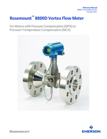
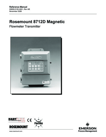
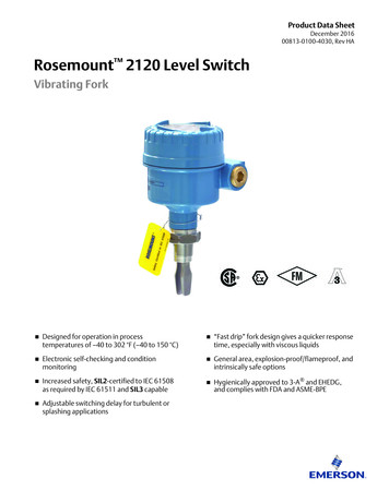
Product Data Sheet00813-0100-4004, Rev KGAugust 2019Rosemount 8800D Vortex FlowmeterIndustry Leading Vortex HART and FOUNDATION Fieldbus Protocols All welded, non-clog design provides maximum performance, reliability and enhanced safety by eliminating ports and gaskets. CriticalProcess increases process availability and enhances overall safety. SIL 2/3 Capable: IEC 61508 certified by an accredited 3rd party agency for use in safety instrumented systems up to SIL 3. Available with optional multivariable output. Internal temperature compensation provides cost-effective saturated steam andliquid mass flow measurement. Adaptive Digital Signal Processing (ADSP) provides vibration immunity and flow range optimization. Reducer Vortex extends the measurable flow range, reduces installation costs, and minimizes project risk. Simplified troubleshooting through device diagnostics and meter verification. Available in wafer, flanged, dual, weld end, and reducer and high pressure designs.
August 2019Product OverviewThe Rosemount 8800D delivers reliability, safety, and maximum processavailability Rosemount Reliability—The Rosemount 8800D Vortex eliminates impulse lines, ports, and gaskets to improve reliability. Non-clog Design—Unique all welded, gasket-free construction which has no ports or crevices that can clog. SIL 2/3 Capable - The Rosemount 8800D Vortex is certified by an accredited 3rd party agency for use in safety instrumentedsystems up to SIL 3 (minimum requirement of single use [1oo1] for SIL 2 and redundant use [1oo2] for SIL 3). Vibration Immunity—Mass balancing of the sensor system, and Adaptive Digital Signal Processing (ADSP) provide vibrationimmunity. Replaceable Sensor—The sensor is isolated from the process and can be replaced without breaking the process seal. All line sizesuse the same sensor design allowing a single spare to serve every meter. Simplified Troubleshooting—Device Diagnostics enable field verification of meter electronics and sensor without processshutdown.ContentsProduct Overview. 2Flow rate sizing.7Ordering Information. 8Product Specifications. 16Product certifications. 30Dimensional drawings. 302www.emerson.com/vortex
August 2019The Rosemount 8800D Critical Process Vortex increases process availability andenhances overall safetyEliminate bypass piping for critical process installationsTraditional vortex installations in critical applications include a bypass line to allow process fluid to be re-directed around the vortexflow meter during routine sensor maintenance. Rosemount's unique non-wetted sensor can be installed without bypass piping,even in the most difficult process environments.Improve process availabilityEliminate the need to shut down the process during routine maintenance and meter verification.Enhances safety in hazardous process fluid applicationsA Critical Process Valve (CPA option) enables access to the sensor cavity to verify that no process fluid is present.www.emerson.com/vortex3
August 2019Reduce installed costs, simplify installation and improve performance in liquid and steam flow applications with the Rosemount 8800D MultiVariableMultivariable vortex designIncorporates temperature sensor into the vortex meter using the shedder bar as a thermowell, which keeps the vortex andtemperature sensors isolated from process for easy verification and replacement.Temperature compensated capability for saturated steamCalculates density from measured process temperature and uses the calculated density to provide a temperature compensatedmass flow. Compensated mass flow using integrated ASME steam tables.Temperature compensated liquids allows for precision measurement of high temperature liquids by correctingthe liquid density as the process temperature changes Select from water or enter up to five temperature and density pairs to accommodate any liquid type. Water density calculations consistent with IAPWS IF-97. New units of measure such as standard barrels, SBBL, are selectable in the corrected volumetric flow measurement mode.Reduces installation costsMultiVariable Vortex eliminates the need for an external thermowell and temperature sensor.Available with integrated thermowell for flanged (1½ inch through 12 inch) and Reducer Vortex (2 inchthrough 12 inch) meter body sizesTo order meter with temperature compensated liquids or temperature compensated steam, include MTA in the model string. Forsmaller line sizes, consult your Emerson Flow representative.4www.emerson.com/vortex
August 2019Available with flow computer for additional functionalityIntegrating the Multivariable vortex flow meter with a pressure transmitter for full pressure and temperature compensation ofsuperheated steam and various gases provides the following additional functionality: Remote communications Heat flow calculations Remote totalization Peak demand calculation Data logging capabilitiesContact an Emerson Flow representative for more information (see back page).Maximum reliability and reduced installation complexity with the armoredremote cable Improved protection against abrasion, impact, and moisture. Available in 10, 20, 33, 50, and 75 foot (3, 6, 10, 15, and 23 m) lengths. Two cable glands are provided to securely connect the remote cable to transmitter and meter body. The cable gland material will match the material of construction of the mating parts at both the meter body end andtransmitter end. The cable gland that connects to the meter body will utilize a stainless steel gland and the cable gland materialwww.emerson.com/vortex5
August 2019at the electronics end will be either aluminum or stainless steel depending on the material of the electronics housing that isordered.Detect process fluid changes with SMART Fluid DiagnosticsOil and gas separators Remotely detect when your separator dump valve allows gas to pass through your water dump leg. Selectable alert modes (digital, analog or pulse) signal when gas flow is detected.Steam, nitrogen, or air blow down Control your clean in place (CIP) or blow down cycles with a single meter that measures the flow rate of your primary processfluid as well as the change from liquid to gas flow. Set your control system to control down cycle based on alert from in-line vortex meter. Selectable alert modes (digital, analog or pulse) signal when gas flow is detected.6www.emerson.com/vortex
August 2019Access process variables and diagnostics locally with the optional LCD ONSECURITYSECURITYOFFONOFFONOFFThe optional 11 digit, two-line integral LCD display can be configured to alternate between selected display options (e.g., flow,totalizer, mA output, and (MTA) temperature. Diagnostics and fault conditions, when present, will also appear on the display forlocal troubleshooting.Flow rate sizingSizing is critical to select the correct Vortex meter for each application is critical to the performance of the Vortex meter. Refer to the product reference manual for typical flow rates for common applications. Go to the Rosemount 8800D Product Page, and select Size for detailed sizing on most applications, or complete aConfiguration Data Sheet and contact an Emerson Flow representative (see back page).www.emerson.com/vortex7
August 2019Ordering InformationModel code structureIn conjunction with a complete model code string, we strongly recommend every meter be configured at the factory for yourapplication. Use the Configuration Data Sheet (00806-0100-4004) to convey your configuration information to the factory.Example model code with one selection out of each required category:8800D F 020 S A1 N 1 D 1 M5 MTA Q4 Q8The starred ( ) offerings represent the best delivery options.RequirementsTable 1: Requirements - select one from each available choiceCodeDescriptionBase modelVortex Flow Meter FFlanged WWafer RReducer – Meter body is one nominal size smaller than line size selection DDual-sensor (flanged-style only)8800DMeter styleLine size005(1)½ inch (15 mm) 0101 inch (25 mm) 0151½ inch (40 mm) 0202 inch (50 mm) 0303 inch (80 mm) 0404 inch (100 mm) 0606 inch (150 mm) 0808 inch (200 mm) 10010 inch (250 mm)12012 inch (300 mm)140(2)14 inch (350 mm)Wetted materialsS316 wrought stainless and CF-3M cast stainless; Material of construction is 316/316L.H(3)UNS N06022 wrought nickel alloy; CW2M cast nickel alloy.CA105 forged carbon steel and WCB cast carbon steelLLF2 forged carbon steel and LCC cast carbon steelD(4)UNS S32760 wrought duplex stainless steel and 6A cast duplex stainless steel8 www.emerson.com/vortex
August 2019Table 1: Requirements - select one from each available choice (continued)CodeDescriptionProcess connection style and pressure ratingA1ASME B16.5 (ANSI) RF Class 150 A3ASME B16.5 RF Class 300 A6ASME B16.5 RF Class 600A7(5)ASME B16.5 RF Class 900A8(6)ASME B16.5 RF Class 1500B1(7)ASME B16.5 RTJ Class 150 for flange-style onlyB3ASME B16.5 RTJ Class 300 for flange-style onlyB6ASME B16.5 RTJ Class 600 for flange-style onlyB7(5)ASME B16.5 RTJ Class 900 for flange-style onlyB8(6)ASME B16.5 RTJ Class 1500 for flange-style onlyC1ASME B16.5 RF Class 150, smooth finishC3ASME B16.5 RF Class 300, smooth finishC6ASME B16.5 RF Class 600, smooth finishC7(5)ASME B16.5 RF Class 900, smooth finishC8(6)ASME B16.5 RF Class 1500, smooth finishK0EN 1092-1 PN 10 Type B1K1EN 1092-1 PN 16 (PN 10/16 for wafer style) Type B1K2EN 1092-1 PN 25 Type B1K3EN 1092-1 PN 40 (PN 25/40 for wafer style) Type B1K4EN 1092-1 PN 63 Type B1K6EN 1092-1 PN 100 Type B1K7(5)EN 1092-1 PN 160 Type B1L0EN 1092-1 PN 10 Type B2L1EN 1092-1 PN 16 (PN 10/16 for wafer style) Type B2L2EN 1092-1 PN 25 Type B2L3EN 1092-1 PN 40 (PN 25/40 for wafer style) Type B2L4EN 1092-1 PN 63 Type B2L6EN 1092-1 PN 100 Type B2L7(5)EN 1092-1 PN 160 Type B2M0EN 1092-1 PN 10 Type D for flange style onlyM1EN 1092-1 PN 16 Type D for flange style onlyM2EN 1092-1 PN 25 Type D for flange style onlyM3EN 1092-1 PN 40 Type D for flange style onlyM4EN 1092-1 PN 63 Type D for flange style onlywww.emerson.com/vortex 9
August 2019Table 1: Requirements - select one from each available choice (continued)CodeDescriptionM6EN 1092-1 PN 100 Type D for flange style onlyM7(5)EN 1092-1 PN 160 Type D for flange style onlyN0EN 1092-1 PN 10 Type FN1EN 1092-1 PN 16 Type FN2EN 1092-1 PN 25 Type FN3EN 1092-1 PN 40Type FN4EN 1092-1 PN 63 Type FN6EN 1092-1 PN 100 Type FN7EN 1092-1 PN 160 Type FJ1JIS 10KJ2JIS 20KJ4JIS 40KW1(8)Weld-end, Schedule 10SW4(8)Weld-end, Schedule 40SW8(7)(8)Weld-end, Schedule 80SW9(8)Weld-end, Schedule 160SSensor process temperature rangeNStandard: –40 to 450 F (–40 to 232 C) E(9)Extended: –330 to 800 F (–200 to 427 C) S(9)Severe service: –330 to 800 F (–200 to 427 C) and nickel alloy construction for increasedcorrosion resistanceHousing material and conduit entries1Aluminum housing, two ½–14 NPT conduit entries 2(10)Aluminum housing, two M20 x 1.5 conduit entries 3(10)Aluminum housing, two PG 13.5 conduit adapters 4Aluminum housing, one G1/2 conduit adapter (one conduit entry) 5Aluminum housing, two G1/2 conduit adapters (two conduit entries) 6Stainless steel housing, two ½–14 NPT conduit entries7(10)Stainless steel housing, two M20 x 1.5 conduit entriesOutputsD4–20 mA digital electronics (HART protocol) P4–20 mA digital electronics (HART protocol) with scaled pulse F(11)FOUNDATION Fieldbus digital signal Flow calibration Calibration110www.emerson.com/vortex
August 2019Not available for Rosemount 8800DR.Code 140 (14 inch [350 mm]) size is only available with reducer.See Table 3 for collared vs. weld neck flange configuration.Available in Flanged and Dual from 6 inch through 12 inch and Reducer from 8 inch through 12 inch Class 1500 in 6 inch and 8 inch meter bodysizes and Class 900 in 10 inch through 12 inch meter body sizes.(5) Available on flanged and dual style meters from 1/2- through 8-in. (15–200 mm) and reducer style meters from 1– 8-in. (25–200 mm). Alsoavailable in 10- through12-in. (250-300 mm) flanged and dual meters along with 12-in. (300 mm) reducers when using Super Duplex material ofconstruction.(6) Only available for flange and dual style meters from 1 inch through 8 inch (25–200 mm).(7) Not available with ½ inch line size.(8) Only available with Meter Style F.(9) The meter body and sensor, in remote mount configurations, is functionally rated to 842 F process temperature. Process temperature may befurther restricted depending on hazardous area options and PED certificates. Consult applicable certificates for particular installation limits. –320 F to 800 F (–196 to 427 C) for European Pressure Equipment Directive (PED), consult factory for lower temperature requirements. The SuperDuplex material of construction is limited to use in applications with process temperatures from –40 to 450 F (–40 to 232 C).(10) No Japan (E4) approval.(11) The Safety Certifications SI option code is not available with this option.(1)(2)(3)(4)OptionsSelect only as needed.Table 2: OptionsCodeDescriptionHazardous area approvalsE5US Approvals Explosion-proof and Dust Ignition-proof I5US Approvals Intrinsically Safe and Non-Incendive IE(1)US Approvals FISCO Intrinsically Safe and Non-Incendive K5US Approvals Explosion-proof, Dust Ignition-proof, Intrinsically Safe, and Non-Incendive E6US/Canadian Approvals Explosion-proof and Dust Ignition-proof I6US/Canadian Approvals Intrinsically Safe and Division 2 IF(1)US/Canadian Approvals FISCO Intrinsically Safe and Division 2 K6US/Canadian Approvals Explosion-proof, Dust Ignition-proof, Intrinsically Safe, and Division 2 KBUS/Canadian Approvals Explosion-proof, Dust Ignition-proof, Intrinsically Safe, and Division 2 E1ATEX Flameproof I1ATEX Intrinsic Safety ia; Intrinsic Safety ic IA(1)ATEX FISCO Intrinsic Safety N1ATEX Type n NDATEX Dust K1ATEX Flameproof; Intrinsic Safety; Type n; Dust E7IECEx Flameproof I7IECEx Intrinsic Safety IG(1)IECEx FISCO Intrinsic Safety N7IECEx Type n NFIECEx Dust K7IECEx Flameproof; Intrinsic Safety; Type n; Dust E2INMETRO Flameproof www.emerson.com/vortex11
August 2019Table 2: Options (continued)CodeDescriptionI2INMETRO Intrinsic Safety IB(1)INMETRO FISCO Intrinsic Safety K2INMETRO Flameproof; Intrinsic Safety E3China Flameproof I3China Intrinsic Safety N3China Type n IH(1)China FISCO/FNICO Intrinsic Safety K3China Flameproof; Dust; Intrinsic Safety; Type n E4Japan Flameproof E8Technical Regulations Customs Union (EAC) Flameproof I8Technical Regulations Customs Union (EAC) Intrinsic Safety N8Technical Regulations Customs Union (EAC) Type n K8Technical Regulations Customs Union (EAC) Flameproof; Intrinsic Safety; Type n G8Technical Regulations Customs Union (EAC) FISCO Intrinsic Safety MultiVariable output with temperature compensation and integral temperature sensor LCD indicator MultiVariableMTA(2)(3)Display typeM5Remote electronicsR10Remote electronics with 10 ft (3,0 m) cable R20Remote electronics with 20 ft (6,1 m) cable R30Remote electronics with 30 ft (9,1 m) cable R33Remote electronics with 33 ft (10,1m) cable R50Remote electronics with 50 ft (15,2 m) cable R75Remote electronics with 75 ft (22,9 m) cable RxxRemote Electronics with customer-specified cable length (xx ft., 1 ft to 75 ft cable in 1 ftincrements)Example: R15 15 ft, R34 34 ftA10Armored remote electronics with 10 ft (3,0 m) cableA20Armored remote electronics with 20 ft (6,1 m) cableA33Armored remote electronics with 33 ft (10,1 m) cableA50Armored remote electronics with 50 ft (15,2 m) cableA75Armored remote electronics with 75 ft (22,9 m) cableTransient protectionT112Transient Protection terminal blockwww.emerson.com/vortex
August 2019Table 2: Options (continued)CodeDescriptionAlarm modeC4(4)NAMUR alarm and saturation values, high alarm CN(4)NAMUR alarm and saturation values, low alarm Cleaning for special services Special cleaningP2Ground screw assemblyV5 External ground screw assembly Plantweb control functionalityA01(5)Basic Control: One Proportional/Integral/Derivative (PID) Function Block ASME B31.1 code complianceJ2ASME B31.1 General complianceJ7ASME B31.1 Boiler External Piping (BEP) code stampConduit electrical connectorsGE(6)M12, 4-pin, Male Connector (eurofast )GM(6)A size Mini, 4-pin, Male Connector (minifast )GNATEX Flameproof A size, Mini 4-pin male connector (minifast)HART communicationHR7(7) HART Revision 7Process diagnosticsDS3(7) Smart Fluid DiagnosticsSafety certificationsSafety Certification of 4–20 mA Output per IEC 61508 Q4Calibration CertificationCertificate of calibration Q5Hydrostatic CertificationCertificate verifying structural quality Q8Material CertificationCertificate of material conformance andtraceability in accordance with ISO 10474 3.1Band EN 10204 3.1 QPCalibration Certification and Tamper EvidentSealCertificate of calibration with tamper evidentseal Q25NACE CertificationCertificate verifying MR0175 / ISO15156 andMR0103 requirements Q66Welding Certification PackageIncludes Welding Qualification RecordDocumentation (PQR), Certificate for WelderPerformance Qualification Records (WPQ), andCertification for Welding ProcedureSpecifications (WPS) Q70Radiographic, Dye Pen, and Helium Certification Certificate verifying weld joint integritySIQuality certificatewww.emerson.com/vortex13
August 2019Table 2: Options (continued)CodeDescriptionQ71Radiographic, Dye Pen, and Helium Certification Certificate verifying weld joint integrity with Xwith Imagesray imagesQ76PMI CertificationCertificate verifying chemical composition ofmaterial Q77PMI Certification with Carbon ContentCertificate verifying chemical composition ofmaterial and carbon content Sensor completionWGWitness GeneralPressure Equipment Directive (PED)PD Pressure Equipment Directive (PED)Shipboard approvalsSBSAmerican Bureau of Shipping (ABS) type approval SBVBureau Veritas (BV) type approval SDNDet Norske Veritas (DNV) type approval SLLLloyd’s Register (LR) type approval Critical process vortexCPA(8)Critical Process Online Sensor ReplacementQuick Start Guide language (default is English)YFFrench YGGerman YIItalian YJJapanese YKKorean YMChinese (Mandarin) YPPortuguese YRRussian YSSpanish (1) Fieldbus Intrinsic Safe Concept (FISCO) available with output code F (Foundation Fieldbus digital signal) only.(2) The Safety Certifications SI option code is not available with this option.(3) Available with Rosemount 8800DF from 1½ inch through 12 inch (40 mm through 300 mm). Available with 8800DR from 2 inch through 12 inch(4)(5)(6)(7)(8)14(50 mm through 300 mm). Not available with 8800DW or 8800DD.NAMUR compliant operation and the alarm latch options are preset at the factory and can be changed to standard operation in the field.Requires output code F.Not available with certain hazardous location certifications. Contact an Emerson Flow representative for details (see back page).The Safety Certifications SI option code is not available with this option.The CPA option is not available on wafer, ½ inch flange, or 1 inch reducer units. In addition it is not available on 1 inch flanged and 1½ inchreducer JIS 10K, EN PN40, or EN PN16. Not available with Super Duplex or B31.1 line sizes greater than 6 inch.www.emerson.com/vortex
August 2019Table 3: Material of construction details for wetted material code HFlange rating codeLine size in. (mm)A1A3A6A7K1K3K4K6K7½ (15)CCCWWWNAWW1 (25)CCCWWWNAWW1½ (40)CCCWWWNAWW2 (50)CCCWCCWWW3 (80)CCCWCCWWW4 (100)CCCWCCWWW6 (150)CCC*WWWW*8 (200)CCC*WWWW*10 (250)WWWNAWWWWNA12 (300)WWWNAWWWWNA14 (350) Reducer only WWWWWWWWWCNickel alloy collar and 316 SST lap flange (Table 4). If weld neck flange is required, please consult factory.WNickel alloy weld neck flange (Table 4).*Contact an Emerson Flow representative (see back page).NANot Available.All Rosemount 8800DR Reducer Vortex Meters with nickel alloy materials of construction use weld neck flanges.All other listed flange rating codes use weld neck flanges.Table 4: Flange illustrationsCollar/lapwww.emerson.com/vortexWeld neck15
August 2019Product SpecificationsPhysical specificationsProcess fluidsLiquid, Gas, and Steam applications. Fluids must be homogeneous and single-phase.Flow calibrationEvery Emerson Vortex flowmeter is water calibrated and given a unique calibration number called a reference K-factor. Emersonflow labs use traceable calibrations that reference internationally recognized standards such as NIST in the United States andMexico, National Institute of Standards in China, and ISO 10725 in Europe.Theoretical and experimental data have shown that the K-factor is independent of fluid density and viscosity, proving the K-factor isapplicable in all types of fluid—liquid, gas and steam. The K-factor is a function of the shedder bar and meter geometry.Line sizes and pipe schedulesTable 5: Line sizes by process connection typeLine sizeInchesProcess connection type ( indicates availability)DINFlangedStandardDualWaferWeld-end Reducer0.515 125 1.540 250 380 4100 6150 8200 10250 12300 14350 Process pipe schedulesMeters will be shipped from the factory at the Schedule 40 default value unless otherwise specified. The value can be changed inthe field if necessary.For a weld-end style meter, see Table 11.Table 6: Wetted materials by componentProcess wetted materialsMeter bodyFlangesCollarCF–3M cast stainless steel316 / 316 L stainless steelN06022 nickel alloy(1)CW2M cast nickel alloyN06022 nickel alloy weld neckN06022 wrought nickel alloy(2)16www.emerson.com/vortex
August 2019Table 6: Wetted materials by component (continued)Process wetted materialsMeter bodyFlangesCollarWBB cast carbon steelA105 forged carbon steelLCC cast carbon steelLF2 forged carbon steel6A duplex stainless steelUNS S32760 wrought duplex stainlesssteel(1) Mated with 316/316L stainless steel lap flange.(2) Applicable to 10 inch and 12 inch meters only.Surface finish Standard surface facing finish meets the requirements of the applicable flange standard. Optional smooth facing finish (flange option codes Cx) is 63 to 125 μ inches (1.6 to 3.1 μ meters) Ra roughness.NACE compliance Materials of Construction meet NACE material recommendations per MR0175 / ISO15156 for use in H₂S containingenvironments in oil field production. Materials of Construction also meet NACE recommendations per MR0103-2003 for corrosive petroleum refining environments. MR0103/MR0103 compliance requires Q25 option in model code.Table 7: Non-wetted materials by componentNon-wetted MaterialsSensor316 SST or Monel / IconelLap Flange316 / 316 L SSTType N Thermocouple304 Stainless SteelTransmitter support tube316 Stainless SteelTransmitter housingAluminum or 316 Stainless SteelPressure limitsTable 8: Flanged/Dual style meterASME 16.5EN1092-1JISClass 150PN 1010KClass 300PN 1620KClass 600PN 2540KClass 900PN 40Class 1500PN 63PN 100PN 160www.emerson.com/vortex17
August 2019Table 9: Reducer style meterASME 16.5EN1092-1Class 150PN 10Class 300PN 16Class 600PN 25Class 900PN 40Class 1500PN 63PN 100PN 160Table 10: Wafer style meterASME 16.5EN1092-1JISClass 150PN 1010KClass 300PN 1620KClass 600PN 2540KPN 40PN 63PN 100Table 11: Weld-end style meterW1W4W8W9Schedule 10Schedule 40Schedule 80Schedule 160Pressure rating for 1inch to 4 inch sizes:720 psig (4.96 MPa-g)1440 psig (9.93 MPa-g)2160 psig (14.9 MPa-g)3600 psig (24.8 MPa-g)Pressure rating for 6inch to 12 inch sizes:N/A720 psig (4.96 MPa-g)1440 psig (9.93 MPa-g)2160 psig (14.9 MPa-g)Mating pipe schedule:Temperature limitsTable 12: Vortex sensor temperature limitsVortex sensorTemperature limitStandard–40 F to 450 F (–40 C to 232 C)Extended–330 F to 800 F (–201 C to 427 C)Severe(1)–330 F to 800 F (–201 C to 427 C)(1) The meter body and sensor, in remote mount configurations, is functionally rated to 842 F process temperature. Processtemperature may be further restricted depending on hazardous area options and PED certificates. Consult applicable certificatesfor particular installation limits.–320 F to 800 F (–196 to 427 C) for European Pressure Equipment Directive (PED), Contact an Emerson Flow representative(see back page).The Super Duplex material of construction is limited to use in applications with process temperatures from –40 to 450 F (–40 to 232 C). Contact an Emerson Flow representative (see back page).18www.emerson.com/vortex
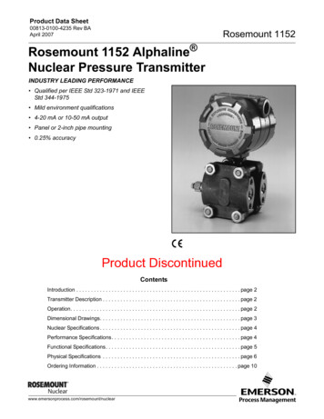
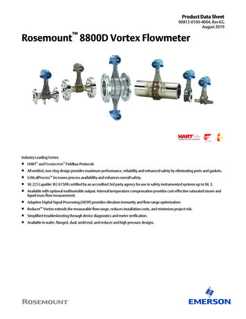
August 2019Table 13: Temperature sensor (MTA option) temperature limitsTemperature sensorTemperature limitType N thermocouple–40 F to 800 F (–40 C to 427 C)(1)(1) Meets ASTM E230/E230M-17 Special Tolerance Standard.Table 14: Electronics temperature limits (remotely-mounted transmitter)Ambient operating temperature range–58 F to 185 F (–50 C to 85 C)Ambient operating temperature rangewith LCD—Local Indicator(1)–40 F to 185 F (–40 C to 85 C)Storage temperature range–58 F to 250 F (–50 C to 121 C)Storage temperature range with LCD–50 F to 185 F (–46 C to 85 C)(1) LCD contrast may be affected below –4 F (–20 C).Table 15: Electronics temperature limits (integrally-mounted transmitter)Operating and storage temperaturerange, with and without LCDSame as remotely-mounted transmitter. See Table 14. However, high processtemperature lowers the maximum allowable ambient temperature. See Figure 1.Maximum process temperatureInterdependent with ambient temperature. Figure 1 indicates the combined ambientand process temperature limits under which the electronics temperature can bemaintained below the maximum 185 F ( 85 C).NoteThe indicated limit is with the integral transmitter directly above a horizontal pipe,and the pipe insulated with three inches of ceramic fiber. Other configurations mayaffect the actual electronics temperature. PELHQW WHPSHUDWXUHFigure 1: Maximum ambient/process temperature limit br) br& br) br& br) br& br) br&7HPSHUDWXUHOLPLW IRU KRXVLQJ br) br& br) br& br) br& br) br& br) br& br) br& br) br& br) br& br) br& br) br& br) br& br) br& br) br& br) 3URFHVV WHPSHUDWXUHEMI/RFI effect Meets EMC requirements to Directive 2014/30/EU. Output error less than 0.025% of span with twisted pair from 80-1000 MHz for radiated field strength of 10 V/m. 1.4 - 2.0 GHz for radiated field strength of 3 V/m.www.emerson.com/vortex19
August 2019 2.0 - 2.7 GHz for radiated field strength of 1 V/m. No affect on the values that are being given if using HART digital signal. Tested per EN61326.Humidity limitsOperates in 0–95% relative humidity under noncondensing conditions (tested to IEC 60770, Section 6.2.11).Transmitter housing detailsTable 16: Transmitter housing (enclosure) physical detailsMaterial of constructionLow-copper aluminum is standard. 316 SST is optional.Enclosure ratingCSA Type 4X; IP66.Conduit entry½–14 NPT or M20 x 1.5 threadsPaintPolyurethaneCover O-ringsBuna -NRemote transmitter mounting hardware and cables Mounting hardware is provided. The transmitter and meter body are interconnected by a standard or armored signal cable assembly.— Cable length is specified when ordered (see Ordering Information), and it cannot be altered in the field.— Standard cable is non-armored and is intended to be run through rigid metal conduit.— Armored cable includes glands/adapters to connect the cable to the meter body and transmitter.— Both types of cable are flame resistant in accordance with IEC 60322-3.Tagging Standard tags are stainless steel. The standard tag is permanently attached to the flowmeter. Character height is 1/16 inch (1,6 mm). A wired-on tag is available on request. Character height on the wire-on tag is 0.236 inch (6 mm). Wire on tags can contain five lines with an average of 19 characters per line at standard character height.Performance specificationsThe following performance specifications are for all Rosemount models except where noted. Digital performance specificationsapplicable to both Digital HART and FOUNDATION Fieldbus output. Unless stated otherwise, all accuracy specifications includelinearity, hysteresis, and repeatability.Volume flow accuracyTable 17: Volume flow accuracyProcess fluidDigital and pulse outputLiquids with Reynolds number over 20,000 0.65% of rate(1)(2)Gas and steam with Reynolds number over 15,000 1.0% of rate(3)(2)20www.emerson.com/vortex
August 2019Table 17: Volume flow accuracy (continued)Process fluidDigital and pulse outputFor all process fluids from stated limit to a Reynolds number of10,000From process limit specification to 2% linear increaseFor Reynolds numbers less than 10,000 to 5,000 2% to 6%, linear(1) 6 inch to 12 inch reducer (150 mm to 300 mm) 1.0% of rate.(2) Analog 0.025% of span(3) 6 inch to 12 inch reducer (150 mm to 300 mm): 1.35% of rate.Accuracy limitations for gas and steam: For ½ inch and 1 inch (DN 15 and DN 25); max velocity of 220 ft/s (67.06 m/s) For all dual shedder bar design meters: max velocit
The Rosemount 8800D delivers reliability, safety, and maximum process availability Rosemount Reliability—The Rosemount 8800D Vortex eliminates impulse lines, ports, and gaskets to improve reliability. Non-clog Design—Unique all welded, gasket-free construction which has no ports or crevices that can clog.