Transcription
Reference Manual00809-0100-4004, Rev CAJune 2012Rosemount 8800D Series Vortex Flowmeter
Title PageReference ManualJune 201200809-0100-4004, Rev CARosemount 8800DSeries Vortex FlowmeterRead this manual before working with the product. For personal and system safety, and foroptimum product performance, make sure you thoroughly understand the contents beforeinstalling, using, or maintaining this product.Within the United States, Rosemount Inc. has two toll-free assistance numbers:Technical support, quoting, and order-related questions.1-800-522-6277 (7:00 am to 7:00 pm CST)North American Response CenterEquipment service needs.1-800-654-7768 (24 hours—includes Canada)Outside of the United States, contact your local Emerson Process Managementrepresentative.The products described in this document are NOT designed for nuclear-qualifiedapplications. Using non-nuclear qualified products in applications that requirenuclear-qualified hardware or products may cause inaccurate readings.For information on Rosemount nuclear-qualified products, contact your local EmersonProcess Management Sales Representative.i
Title PageJune 2012iiReference Manual00809-0100-4004, Rev CA
Reference ManualTable of Contents00809-0100-4004, Rev CAJune 2012Contents1Section 1: Introduction1.1 How to use this manual. . . . . . . . . . . . . . . . . . . . . . . . . . . . . . . . . . . . . . . . . . . . . . . . . . 11.2 Safety messages . . . . . . . . . . . . . . . . . . . . . . . . . . . . . . . . . . . . . . . . . . . . . . . . . . . . . . . . 11.3 System description . . . . . . . . . . . . . . . . . . . . . . . . . . . . . . . . . . . . . . . . . . . . . . . . . . . . . 22Section 2: Installation2.1 Safety messages . . . . . . . . . . . . . . . . . . . . . . . . . . . . . . . . . . . . . . . . . . . . . . . . . . . . . . . . 32.2 Commissioning. . . . . . . . . . . . . . . . . . . . . . . . . . . . . . . . . . . . . . . . . . . . . . . . . . . . . . . . . 52.2.1 General considerations . . . . . . . . . . . . . . . . . . . . . . . . . . . . . . . . . . . . . . . . . . . . 52.2.2 Flowmeter sizing. . . . . . . . . . . . . . . . . . . . . . . . . . . . . . . . . . . . . . . . . . . . . . . . . . 52.2.3 Flowmeter orientation. . . . . . . . . . . . . . . . . . . . . . . . . . . . . . . . . . . . . . . . . . . . . 52.2.4 Wetted material selection. . . . . . . . . . . . . . . . . . . . . . . . . . . . . . . . . . . . . . . . . . 72.2.5 Environmental considerations . . . . . . . . . . . . . . . . . . . . . . . . . . . . . . . . . . . . . . 72.3 Hazardous locations . . . . . . . . . . . . . . . . . . . . . . . . . . . . . . . . . . . . . . . . . . . . . . . . . . . . 82.4 Hardware configuration . . . . . . . . . . . . . . . . . . . . . . . . . . . . . . . . . . . . . . . . . . . . . . . . . 82.4.1 Failure mode vs. saturation output values . . . . . . . . . . . . . . . . . . . . . . . . . . . . 92.4.2 LCD indicator option . . . . . . . . . . . . . . . . . . . . . . . . . . . . . . . . . . . . . . . . . . . . . . 92.5 Meter body installation tasks . . . . . . . . . . . . . . . . . . . . . . . . . . . . . . . . . . . . . . . . . . . .102.5.1 Handling . . . . . . . . . . . . . . . . . . . . . . . . . . . . . . . . . . . . . . . . . . . . . . . . . . . . . . . .102.5.2 Flow direction . . . . . . . . . . . . . . . . . . . . . . . . . . . . . . . . . . . . . . . . . . . . . . . . . . .112.5.3 Gaskets . . . . . . . . . . . . . . . . . . . . . . . . . . . . . . . . . . . . . . . . . . . . . . . . . . . . . . . . .112.5.4 Flange bolts . . . . . . . . . . . . . . . . . . . . . . . . . . . . . . . . . . . . . . . . . . . . . . . . . . . . .112.5.5 Wafer-style flowmeter alignment and mounting . . . . . . . . . . . . . . . . . . . . .122.5.6 Flanged-style flowmeter mounting. . . . . . . . . . . . . . . . . . . . . . . . . . . . . . . . .152.5.7 Flowmeter grounding . . . . . . . . . . . . . . . . . . . . . . . . . . . . . . . . . . . . . . . . . . . .172.6 Electronics considerations . . . . . . . . . . . . . . . . . . . . . . . . . . . . . . . . . . . . . . . . . . . . . .182.6.1 High-temperature installations . . . . . . . . . . . . . . . . . . . . . . . . . . . . . . . . . . . .182.6.2 Conduit connections . . . . . . . . . . . . . . . . . . . . . . . . . . . . . . . . . . . . . . . . . . . . .182.6.3 High-point installation . . . . . . . . . . . . . . . . . . . . . . . . . . . . . . . . . . . . . . . . . . . .182.6.4 Cable gland . . . . . . . . . . . . . . . . . . . . . . . . . . . . . . . . . . . . . . . . . . . . . . . . . . . . .192.6.5 Grounding the transmitter case. . . . . . . . . . . . . . . . . . . . . . . . . . . . . . . . . . . .192.6.6 Wiring procedure . . . . . . . . . . . . . . . . . . . . . . . . . . . . . . . . . . . . . . . . . . . . . . . .202.6.7 Remote electronics . . . . . . . . . . . . . . . . . . . . . . . . . . . . . . . . . . . . . . . . . . . . . .242.6.8 Calibration . . . . . . . . . . . . . . . . . . . . . . . . . . . . . . . . . . . . . . . . . . . . . . . . . . . . . .262.7 Software configuration . . . . . . . . . . . . . . . . . . . . . . . . . . . . . . . . . . . . . . . . . . . . . . . . .262.7.1 Installing the indicator . . . . . . . . . . . . . . . . . . . . . . . . . . . . . . . . . . . . . . . . . . . .28Table of Contentsiii
Reference ManualTable of Contents00809-0100-4004, Rev CAJune 20122.8 Transient protection . . . . . . . . . . . . . . . . . . . . . . . . . . . . . . . . . . . . . . . . . . . . . . . . . . .302.8.1 Installing the transient protector. . . . . . . . . . . . . . . . . . . . . . . . . . . . . . . . . . .303Section 3: Configuration3.1 Process variables . . . . . . . . . . . . . . . . . . . . . . . . . . . . . . . . . . . . . . . . . . . . . . . . . . . . . .333.1.1 Primary Variable (PV) . . . . . . . . . . . . . . . . . . . . . . . . . . . . . . . . . . . . . . . . . . . . .333.1.2 PV% of range . . . . . . . . . . . . . . . . . . . . . . . . . . . . . . . . . . . . . . . . . . . . . . . . . . . .333.1.3 Analog output . . . . . . . . . . . . . . . . . . . . . . . . . . . . . . . . . . . . . . . . . . . . . . . . . . .333.1.4 Process variable units. . . . . . . . . . . . . . . . . . . . . . . . . . . . . . . . . . . . . . . . . . . . .333.2 Basic setup. . . . . . . . . . . . . . . . . . . . . . . . . . . . . . . . . . . . . . . . . . . . . . . . . . . . . . . . . . . .413.2.1 Tag. . . . . . . . . . . . . . . . . . . . . . . . . . . . . . . . . . . . . . . . . . . . . . . . . . . . . . . . . . . . .413.2.2 Process configuration . . . . . . . . . . . . . . . . . . . . . . . . . . . . . . . . . . . . . . . . . . . .413.2.3 Reference k-factor . . . . . . . . . . . . . . . . . . . . . . . . . . . . . . . . . . . . . . . . . . . . . . .443.2.4 Flange type. . . . . . . . . . . . . . . . . . . . . . . . . . . . . . . . . . . . . . . . . . . . . . . . . . . . . .443.2.5 Pipe ID . . . . . . . . . . . . . . . . . . . . . . . . . . . . . . . . . . . . . . . . . . . . . . . . . . . . . . . . .453.2.6 Variable mapping . . . . . . . . . . . . . . . . . . . . . . . . . . . . . . . . . . . . . . . . . . . . . . . .453.2.7 Process variable units. . . . . . . . . . . . . . . . . . . . . . . . . . . . . . . . . . . . . . . . . . . . .463.2.8 Analog output . . . . . . . . . . . . . . . . . . . . . . . . . . . . . . . . . . . . . . . . . . . . . . . . . . .463.2.9 Damping. . . . . . . . . . . . . . . . . . . . . . . . . . . . . . . . . . . . . . . . . . . . . . . . . . . . . . . .473.2.10Optimize DSP . . . . . . . . . . . . . . . . . . . . . . . . . . . . . . . . . . . . . . . . . . . . . . . . . . .474Section 4: Operation4.1 Diagnostics/service . . . . . . . . . . . . . . . . . . . . . . . . . . . . . . . . . . . . . . . . . . . . . . . . . . . .514.1.1 Device alerts . . . . . . . . . . . . . . . . . . . . . . . . . . . . . . . . . . . . . . . . . . . . . . . . . . . .514.1.2 Loop test. . . . . . . . . . . . . . . . . . . . . . . . . . . . . . . . . . . . . . . . . . . . . . . . . . . . . . . .524.1.3 Flow simulation . . . . . . . . . . . . . . . . . . . . . . . . . . . . . . . . . . . . . . . . . . . . . . . . . .524.1.4 Analog trim . . . . . . . . . . . . . . . . . . . . . . . . . . . . . . . . . . . . . . . . . . . . . . . . . . . . .544.1.5 Scaled analog trim . . . . . . . . . . . . . . . . . . . . . . . . . . . . . . . . . . . . . . . . . . . . . . .544.1.6 Shed freq at URV . . . . . . . . . . . . . . . . . . . . . . . . . . . . . . . . . . . . . . . . . . . . . . . . .544.2 Advanced functionality . . . . . . . . . . . . . . . . . . . . . . . . . . . . . . . . . . . . . . . . . . . . . . . . .544.2.1 Pulse output. . . . . . . . . . . . . . . . . . . . . . . . . . . . . . . . . . . . . . . . . . . . . . . . . . . . .564.2.2 Communications . . . . . . . . . . . . . . . . . . . . . . . . . . . . . . . . . . . . . . . . . . . . . . . .584.2.3 Signal processing . . . . . . . . . . . . . . . . . . . . . . . . . . . . . . . . . . . . . . . . . . . . . . . .624.2.4 Device information. . . . . . . . . . . . . . . . . . . . . . . . . . . . . . . . . . . . . . . . . . . . . . .655Section 5: Troubleshooting5.1 Safety messages . . . . . . . . . . . . . . . . . . . . . . . . . . . . . . . . . . . . . . . . . . . . . . . . . . . . . . .69ivTable of Contents
Reference ManualTable of Contents00809-0100-4004, Rev CAJune 20125.2 Troubleshooting tables . . . . . . . . . . . . . . . . . . . . . . . . . . . . . . . . . . . . . . . . . . . . . . . . .715.3 Advanced troubleshooting. . . . . . . . . . . . . . . . . . . . . . . . . . . . . . . . . . . . . . . . . . . . . .735.3.1 Diagnostic messages . . . . . . . . . . . . . . . . . . . . . . . . . . . . . . . . . . . . . . . . . . . . .735.3.2 Electronics test points . . . . . . . . . . . . . . . . . . . . . . . . . . . . . . . . . . . . . . . . . . . .755.3.3 TP1. . . . . . . . . . . . . . . . . . . . . . . . . . . . . . . . . . . . . . . . . . . . . . . . . . . . . . . . . . . . .765.4 Diagnostic messages on LCD . . . . . . . . . . . . . . . . . . . . . . . . . . . . . . . . . . . . . . . . . . . .785.5 Testing procedures . . . . . . . . . . . . . . . . . . . . . . . . . . . . . . . . . . . . . . . . . . . . . . . . . . . .805.6 Hardware replacement . . . . . . . . . . . . . . . . . . . . . . . . . . . . . . . . . . . . . . . . . . . . . . . . .805.6.1 Replacing the terminal block in the housing . . . . . . . . . . . . . . . . . . . . . . . . .805.6.2 Replacing the electronics boards. . . . . . . . . . . . . . . . . . . . . . . . . . . . . . . . . . .815.6.3 Replacing the electronics housing. . . . . . . . . . . . . . . . . . . . . . . . . . . . . . . . . .835.6.4 Replacing the sensor . . . . . . . . . . . . . . . . . . . . . . . . . . . . . . . . . . . . . . . . . . . . .845.6.5 Replacing the sensor: removable support tube . . . . . . . . . . . . . . . . . . . . . .855.6.6 Remote electronics procedure. . . . . . . . . . . . . . . . . . . . . . . . . . . . . . . . . . . . .905.6.7 Coaxial cable at the electronics housing. . . . . . . . . . . . . . . . . . . . . . . . . . . . .925.6.8 Changing the housing orientation. . . . . . . . . . . . . . . . . . . . . . . . . . . . . . . . . .945.6.9 Temperature sensor replacement(MTA option only)945.7 Return of material . . . . . . . . . . . . . . . . . . . . . . . . . . . . . . . . . . . . . . . . . . . . . . . . . . . . .95AAppendix A: Reference DataA.1 Specifications . . . . . . . . . . . . . . . . . . . . . . . . . . . . . . . . . . . . . . . . . . . . . . . . . . . . . . . . .97A.2 Functional specifications . . . . . . . . . . . . . . . . . . . . . . . . . . . . . . . . . . . . . . . . . . . . . . .97A.3 Performance specifications . . . . . . . . . . . . . . . . . . . . . . . . . . . . . . . . . . . . . . . . . . . 113A.4 Physical specifications . . . . . . . . . . . . . . . . . . . . . . . . . . . . . . . . . . . . . . . . . . . . . . . . 117A.5 Dimensional drawings. . . . . . . . . . . . . . . . . . . . . . . . . . . . . . . . . . . . . . . . . . . . . . . . 120BAppendix B: Approval informationB.1 Product certifications . . . . . . . . . . . . . . . . . . . . . . . . . . . . . . . . . . . . . . . . . . . . . . . . 137B.1.1 Approved manufacturing locations. . . . . . . . . . . . . . . . . . . . . . . . . . . . . . . 137B.2 European Pressure Equipment Directive (PED). . . . . . . . . . . . . . . . . . . . . . . . . . . 138B.3 Hazardous location certifications . . . . . . . . . . . . . . . . . . . . . . . . . . . . . . . . . . . . . . 138B.3.1 Rosemount 8800D . . . . . . . . . . . . . . . . . . . . . . . . . . . . . . . . . . . . . . . . . . . . . 138B.4 International IECEx certifications. . . . . . . . . . . . . . . . . . . . . . . . . . . . . . . . . . . . . . . 142B.4.1 Intrinsic Safety. . . . . . . . . . . . . . . . . . . . . . . . . . . . . . . . . . . . . . . . . . . . . . . . . 142B.4.2 Chinese certifications (NEPSI). . . . . . . . . . . . . . . . . . . . . . . . . . . . . . . . . . . . 144B.4.3 Brazilian certifications - INMETRO . . . . . . . . . . . . . . . . . . . . . . . . . . . . . . . . 145B.4.4 Japanese certifications (TIIS). . . . . . . . . . . . . . . . . . . . . . . . . . . . . . . . . . . . . 146Table of Contentsv
Reference ManualTable of Contents00809-0100-4004, Rev CAJune 2012CAppendix C: Electronics verificationC.1 Safety messages . . . . . . . . . . . . . . . . . . . . . . . . . . . . . . . . . . . . . . . . . . . . . . . . . . . . . 155C.2 Electronics verification . . . . . . . . . . . . . . . . . . . . . . . . . . . . . . . . . . . . . . . . . . . . . . . 156C.2.1 Electronics verification using flow simulation mode . . . . . . . . . . . . . . . . 156C.2.2 Fixed flow rate simulation . . . . . . . . . . . . . . . . . . . . . . . . . . . . . . . . . . . . . . . 156C.2.3 Varying flow rate simulation. . . . . . . . . . . . . . . . . . . . . . . . . . . . . . . . . . . . . 156C.2.4 Electronics verification using an external frequency generator . . . . . . . 157C.2.5 Calculating output variables with knowninput frequency159C.3 Examples . . . . . . . . . . . . . . . . . . . . . . . . . . . . . . . . . . . . . . . . . . . . . . . . . . . . . . . . . . . 162C.3.1 English units. . . . . . . . . . . . . . . . . . . . . . . . . . . . . . . . . . . . . . . . . . . . . . . . . . . 162C.3.2 SI units . . . . . . . . . . . . . . . . . . . . . . . . . . . . . . . . . . . . . . . . . . . . . . . . . . . . . . . 165DAppendix D: HART fast keysviTable of Contents
Section 1: IntroductionReference ManualJune 201200809-0100-4004, Rev CASection 1IntroductionHow to use this manual . . . . . . . . . . . . . . . . . . . . . . . . . . . . . . . . . . . . . . . . . . . . . . . . . . . page 1Safety messages . . . . . . . . . . . . . . . . . . . . . . . . . . . . . . . . . . . . . . . . . . . . . . . . . . . . . . . . . page 11.1How to use this manualThis manual provides installation, configuration, troubleshooting, and other procedures for theuse of the Rosemount 8800D Vortex Flowmeter. For model code ordering information, pleasesee the Rosemount 8800D Series Vortex Flowmeter Product Data Sheet, 00813-0100-4004.Section 2: Installation contains mechanical and electrical installation instructions.Section 3: Configuration contains information on entering and verifying basic configurationparameters.Section 4: Operation contains information on advanced configuration parameters and functionsthat can aid in maintaining the 8800D.Section 5: Troubleshooting provides troubleshooting techniques, diagnostic information, andtransmitter verification procedures.Appendix A: Reference Data provides reference and specification data.Appendix B: Approval information provides specific information for approval codes.Appendix C: Electronics verification provides a short procedure for verification of electronicoutput to assist in meeting the quality standards for ISO 9000 certified manufacturingprocesses.Rosemount 8800D HART Menu Tree for Device Revision 1 and Device Revision 2. (DD Revision1) provides command tree, and Fast Key Sequence tables for the Field Communicator whenused in conjunction with the Rosemount 8800D.1.2Safety messagesProcedures and instructions in this manual may require special precautions to ensure the safetyof the personnel performing the operations. Refer to the safety messages, listed at thebeginning of each section, before performing any operations.Introduction1
Section 1: Introduction1.3Reference Manual00809-0100-4004, Rev CAJune 2012System descriptionThe Rosemount 8800D Vortex Flowmeter consists of a meter body and transmitter, andmeasures volumetric flow rate by detecting the vortices created by a fluid passing by theshedder bar.The meter body is installed in-line with process piping. A sensor is located at the end of theshedder bar and creates an alternating sine wave due to the passing vortices. The transmittermeasures the frequency of the sine waves and converts it into a flowrate.This manual is designed to assist in the installation and operation of the Rosemount 8800DVortex Flowmeter.This product is intended to be used as a flowmeter for liquid, gas, or steam applications.Any use other than for which it was intended may result in serious injury or death.2Introduction
Section 2: InstallationReference ManualJune 201200809-0100-4004, Rev CASection 2InstallationSafety messages . . . . . . . . . . . . . . . . . . . . . . . . . . . . . . . . . . . . . . . . . . . . . . . . . . . . . . . . . page 3Commissioning . . . . . . . . . . . . . . . . . . . . . . . . . . . . . . . . . . . . . . . . . . . . . . . . . . . . . . . . . . page 5Hazardous locations . . . . . . . . . . . . . . . . . . . . . . . . . . . . . . . . . . . . . . . . . . . . . . . . . . . . . page 8Hardware configuration . . . . . . . . . . . . . . . . . . . . . . . . . . . . . . . . . . . . . . . . . . . . . . . . . . page 8Meter body installation tasks . . . . . . . . . . . . . . . . . . . . . . . . . . . . . . . . . . . . . . . . . . . . . page 10Electronics considerations . . . . . . . . . . . . . . . . . . . . . . . . . . . . . . . . . . . . . . . . . . . . . . . . page 18Software configuration . . . . . . . . . . . . . . . . . . . . . . . . . . . . . . . . . . . . . . . . . . . . . . . . . . . page 26Transient protection . . . . . . . . . . . . . . . . . . . . . . . . . . . . . . . . . . . . . . . . . . . . . . . . . . . . . page 30This section provides installation instructions for the Rosemount 8800D Vortex Flowmeter.Dimensional drawings for each Rosemount 8800D variation and mounting configuration areincluded in Appendix A: Reference Data.The options available for the Rosemount 8800D flowmeter are also described in this section.The numbers in parentheses refer to the codes used to order each option.2.1Safety messagesInstructions and procedures in this section may require special precautions to ensure the safetyof the personnel performing the operations. Please refer to the following safety messagesbefore performing any operation in this section.Explosions could result in death or serious injury: Do not remove the transmitter cover in explosive atmospheres when the circuit isalive.Before connecting a HART-based communicator in an explosive atmosphere, makesure the instruments in the loop are installed in accordance with intrinsically safe ornon-incendive field wiring practices.Verify that the operating atmosphere of the transmitter is consistent with theappropriate hazardous locations certifications.Both transmitter covers must be fully engaged to meet explosion-proof requirements.Failure to follow these installation guidelines could result in death or serious injury: InstallationMake sure only qualified personnel perform the installation.3
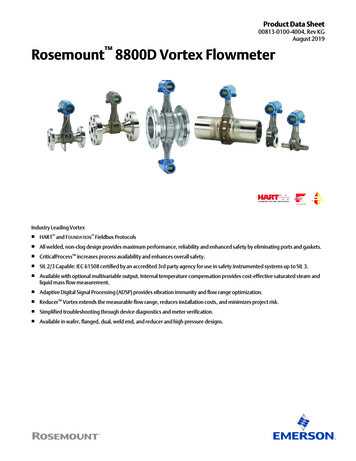
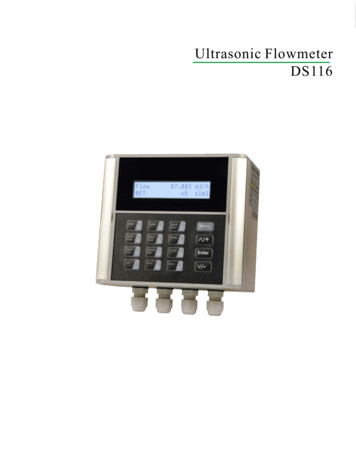
Reference ManualSection 2: Installation00809-0100-4004, Rev CAJune 2012Figure 2-1. Installation FlowchartSTART NFIGUREBFIELDINSTALLTagIsYesConfigurationOK?NoGo to AUsingLCD?YesConfigureLocalDisplayNoUsing PulseOutputProcess Config Transmitter Mode Process Fluid Fixed Process Temp. Dens/Dens Ratio-Density Ratio(Std. or Normal VolumetricFlow Units Only)-Fixed Process Density(Mass Flow Units Only)ReferenceK-FactorConfigurePulseOutputVariable MappingPV UnitRange nge TypeMating Pipe IDYesMountFlowmeterDid youYesConfigure onBench?DONENoReviewConfigurationPV DampingUsingTotalizerYesConfigureTotalizerAuto Adjust FilterConfigure ifNecessaryGo to ANoMeterInstalledYesDONENoGo to B4Installation
Reference ManualSection 2: Installation00809-0100-4004, Rev CA2.2June 2012CommissioningCommission the Rosemount 8800D before putting it into operation. This ensures properconfiguration and operation of the meter. It also enables you to check hardware settings, testthe flowmeter electronics, verify flowmeter configuration data, and check output variables. Anyproblems can be corrected – or configuration settings changed – before going out into theinstallation environment. To commission on the bench, connect the Field Communicator orAsset Management Solutions (AMS) software (or other communications device) to the signalloop in accordance with the specifications for your communicator.2.2.1General considerationsBefore you install a flowmeter in any application, you must consider flowmeter sizing (the linesize) and location. Choose the correct flowmeter size for an application to increase rangeabilityand minimize pressure drop and cavitation. Proper location of the flowmeter can ensure a cleanand accurate signal. Follow the installation instructions carefully to reduce start-up delays, easemaintenance, and ensure optimum performance.2.2.2Flowmeter sizingCorrect meter sizing is important for flowmeter performance. The Rosemount 8800D is capableof processing signals from flow applications within the limitations described in Appendix A:Reference Data.To determine the correct flowmeter size for an application, process conditions must be withinthe stated requirements for Reynolds number and velocity. See Appendix A: Reference Data forsizing data.Contact your local Rosemount Inc. sales representative to obtain a copy of Instrument Toolkit which contains a sizing module for the Rosemount 8800D Vortex flowmeter. The vortex sizingmodule will calculate valid flowmeter sizes based on user-supplied application information.2.2.3Flowmeter orientationDesign process piping so the meter body will remain full, with no entrapped air. Allow enoughstraight pipe both upstream and downstream of the meter body to ensure a nonskewed,symmetrical profile. Install valves downstream of the meter when possible.Vertical installationVertical installation allows upward process liquid flow and is generally preferred. Upward flowensures that the meter body always remains full and that any solids in the fluid are evenlydistributed.The vortex meter can be mounted in the vertical down position when measuring gas or steamflows. This type of application should be strongly discouraged for liquid flows, although it canbe done with proper piping design.NoteTo ensure that the meter body remains full, avoid downward verticalliquid flows where back pressure is inadequate.Installation5
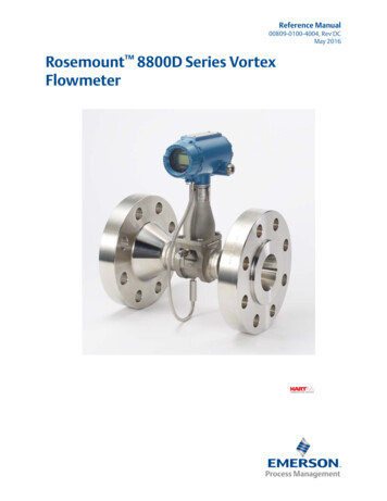
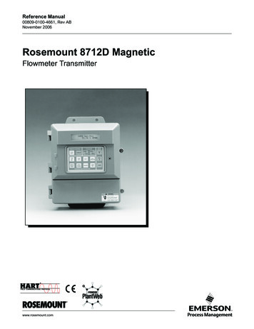
Reference ManualSection 2: Installation00809-0100-4004, Rev CAJune 2012Horizontal installationFor horizontal installation, the preferred orientation is to have the electronics installed to theside of the pipe. In liquid applications, this ensures any entrained air or solids do not strike theshedding bar and disrupt the shedding frequency. In gas or steam applications, this ensures thatany entrained liquid (such as condensate) or solids do not strike the shedder bar and disrupt theshedding frequency.High-temperature installationsInstall the meter body so the electronics are positioned to the side of the pipe or below the pipeas shown in Figure 2-2. Insulation may be required around the pipe to maintain an electronicstemperature below 185 F (85 C). See Figure 2-9 on page 16 for special insulation considerations.Figure 2-2. Examples of High-Temperature InstallationsThe meter body installed with theelectronics to the side of the pipe.(PREFERRED ORIENTATION)The meter body installed with theelectronics below the pipe.(ACCEPTABLE ORIENTATION)Steam installationsFor steam applications, avoid installations such as the one shown in Figure 2-3. Suchinstallations may cause a water-hammer condition at start-up due to trapped condensate. Thehigh force from the water hammer can over stress the sensing mechanism and cause permanentdamage to the sensor.Figure 2-3. Avoid This Type of Installation for Steam Applications6Installation
Reference ManualSection 2: Installation00809-0100-4004, Rev CAJune 2012Upstream/downstream pipingThe vortex meter may be installed with a minimum of ten diameters (D) of straight pipe lengthupstream and five diameters (D) of straight pipe length downstream.Rated accuracy is based on the number of pipe diameter from an upstream disturbance. NoK-factor correction is required if the meter is installed with 35 D upstream and 5 D downstream.The value of the K-factor may shift up to 0.5% when the upstream straight pipe length isbetween 10D and 35D. Please see Technical Data Sheet (00816-0100-3250) on InstallationEffects for optional K-factor corrections. This effect can be corrected for using the InstallationEffect Correction Factor (See page 55).Pressure and temperature transmitter locationWhen using pressure and temperature transmitters in conjunction with the Rosemount 8800Dfor compensated mass flows, install the transmitter(s) downstream of the Vortex Flowmeter.See Figure 2-4.Figure 2-4. Pressure and Temperature Transmitter LocationPNOTE: The MTA option can be purchased for an integraltemperature measurement and mass flow temperaturecompensation for saturated steam only.2.2.4T4 Downstream6 DownstreamWetted material selectionEnsure that the process fluid is compatible with the meter body wetted materials whenspecifying the Rosemount 8800D. Corrosion will shorten the life of the meter body. Consultrecognized sources of corrosion data or contact your Emerson Flow Sales Representative formore information.NoteFor accurate results perform a Positive Material Identification (PMI) test on a machined surface.2.2.5Environmental considerationsAvoid excessive heat and vibration to ensure maximum flowmeter life. Typical problem areasinclude high-vibration lines with integrally mounted electronics, warm-climate installations indirect sunlight, and outdoor installations in cold climates.Installation7
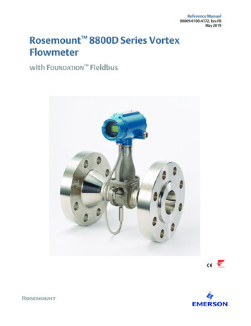
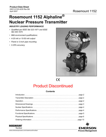
Section 2: InstallationReference Manual00809-0100-4004, Rev CAJune 2012Although the signal conditioning functions reduce susceptibility to extraneous noise, someenvironments are more suitable than others. Avoid placing the flowmeter or its wiring close todevices that produce high intensity electromagnetic and electrostatic fields. Such devices includeelectric welding equipment, large electric motors and transformers, and communicationtransmitters.2.3Hazardous locationsThe Rosemount 8800D has an explosion-proof housing and circuitry suitable for intrinsicallysafe and non-incendive operation. Individual transmitters are clearly marked with a tagindicating the certifications they carry. See Appendix B: Approval information for specificapproval categories.2.4Hardware configurationThe hardware jumpers on the Rosemount 8800D enable you to set the alarm and security. (SeeFigure 2-5.) To access the jumpers, remove the electronics housing cover from the electronicsend of the Rosemount 8800D. If your Rosemount 8800D includes an LCD option, the alarm andsecurity jumpers are found on the face of the LCD indicator. (See Figure 2-6 on page 10.)NoteIf you will be changing configuration variables frequently, it may beuseful to leave the security lockout jumper in the OFF position toavoid exposing the flowmeter electronics to the plant environment.Set these jumpers during the commissioning stage to avoid exposing the electronics to theplant environment.Figure 2-5. Alarm and Security Jumpers8Installation
Reference ManualSection 2: Installation00809-0100-4004, Rev CAJune 2012AlarmAs part of normal operations, the Rosemount 8800D continuously runs a self-diagnosticroutine. If the routine detects an internal failure in the electronics, flowmeter output is driven toa low or high alarm level, depending on the position of the failure mode jumper.The failure mode jumper is labeled ALARM and is set to the high position at the factory per theCDS (Configuration Data Sheet); the default setting is HI.SecurityYou can protect the configuration data with the security lockout jumper. With the securitylockout jumper ON, any configuration changes attempted on the electronics are disallowed.You can still access and review any of the operating parameters and scroll through the availablechanges, but no actual changes will be permitted. The security lockout jumper is labeledSECURITY and is set at the factory per the CDS; the default setting is OFF.2.4.1Failure mode vs. saturation output valuesThe failure mode alarm output levels differ from the output values that occur when theoperating flow is outside the range points. When the operating flow is outside the range points,the analog output continues to track the operating flow until reaching the saturation valuelisted below; the output does not exceed the listed saturation value regardless of the operatingflow. For example, with standard alarm and saturation levels and flows outside the 4—20 mArange points, the output saturates at 3.9 mA or 20.8 mA. When the transmitter diagnosticsdetect a failure, the analog output is set to a specific alarm value that differs from the saturationvalue to allow for proper troubleshooting.Table 2-1. Analog Output: Standard Alarm Values vs. Saturation ValuesLevel4—20 mA Saturation Value4—20 mA Alarm ValueLow3.9 mA 3.75 mAHigh20.8 mA 21.75 mATable 2-2.
The Rosemount 8800D Vortex Flowmeter consis ts of a meter body and transmitter, and measures volumetric flow rate by detecting the vortices created by a fluid passing by the shedder bar. The meter body is installed in-line with process piping. A sensor is located at the end of the