Transcription
Reference Manual00809-0100-4004, Rev DCMay 2016Rosemount 8800D Series VortexFlowmeter
Reference ManualTable of Contents00809-0100-4004, Rev DCMay 2016Contents1Section 1: Introduction1.1 How to use this manual. . . . . . . . . . . . . . . . . . . . . . . . . . . . . . . . . . . . . . . . . . . . . . . . . 11.2 Safety messages . . . . . . . . . . . . . . . . . . . . . . . . . . . . . . . . . . . . . . . . . . . . . . . . . . . . . . . 11.3 System description . . . . . . . . . . . . . . . . . . . . . . . . . . . . . . . . . . . . . . . . . . . . . . . . . . . . 12Section 2: Configuration2.1 Process variables . . . . . . . . . . . . . . . . . . . . . . . . . . . . . . . . . . . . . . . . . . . . . . . . . . . . . . 32.1.1Primary Variable (PV) . . . . . . . . . . . . . . . . . . . . . . . . . . . . . . . . . . . . . . . . . . . 32.1.2Percent of Range . . . . . . . . . . . . . . . . . . . . . . . . . . . . . . . . . . . . . . . . . . . . . . . 32.1.3Analog Output . . . . . . . . . . . . . . . . . . . . . . . . . . . . . . . . . . . . . . . . . . . . . . . . . 32.1.4Process Variable Units. . . . . . . . . . . . . . . . . . . . . . . . . . . . . . . . . . . . . . . . . . . 42.2 Basic setup. . . . . . . . . . . . . . . . . . . . . . . . . . . . . . . . . . . . . . . . . . . . . . . . . . . . . . . . . . .112.2.1Tag . . . . . . . . . . . . . . . . . . . . . . . . . . . . . . . . . . . . . . . . . . . . . . . . . . . . . . . . . . 112.2.2Long Tag . . . . . . . . . . . . . . . . . . . . . . . . . . . . . . . . . . . . . . . . . . . . . . . . . . . . . 112.2.3Process configuration . . . . . . . . . . . . . . . . . . . . . . . . . . . . . . . . . . . . . . . . . . 112.2.4Reference K-factor. . . . . . . . . . . . . . . . . . . . . . . . . . . . . . . . . . . . . . . . . . . . . 122.2.5Flange Type. . . . . . . . . . . . . . . . . . . . . . . . . . . . . . . . . . . . . . . . . . . . . . . . . . . 132.2.6Pipe ID . . . . . . . . . . . . . . . . . . . . . . . . . . . . . . . . . . . . . . . . . . . . . . . . . . . . . . . 132.2.7Variable mapping . . . . . . . . . . . . . . . . . . . . . . . . . . . . . . . . . . . . . . . . . . . . . 142.2.8Process Variable Units. . . . . . . . . . . . . . . . . . . . . . . . . . . . . . . . . . . . . . . . . . 152.2.9Analog Output . . . . . . . . . . . . . . . . . . . . . . . . . . . . . . . . . . . . . . . . . . . . . . . . 152.2.10 Damping . . . . . . . . . . . . . . . . . . . . . . . . . . . . . . . . . . . . . . . . . . . . . . . . . . . . . 162.2.11 Optimize DSP (Digital Signal Processing) . . . . . . . . . . . . . . . . . . . . . . . . . 163Section 3: Installation3.1 Safety messages . . . . . . . . . . . . . . . . . . . . . . . . . . . . . . . . . . . . . . . . . . . . . . . . . . . . . .213.2 Commissioning. . . . . . . . . . . . . . . . . . . . . . . . . . . . . . . . . . . . . . . . . . . . . . . . . . . . . . .233.2.1Flowmeter sizing . . . . . . . . . . . . . . . . . . . . . . . . . . . . . . . . . . . . . . . . . . . . . . 233.2.2Flowmeter orientation . . . . . . . . . . . . . . . . . . . . . . . . . . . . . . . . . . . . . . . . . 233.2.3Wetted material selection . . . . . . . . . . . . . . . . . . . . . . . . . . . . . . . . . . . . . . 253.2.4Environmental considerations. . . . . . . . . . . . . . . . . . . . . . . . . . . . . . . . . . . 263.3 Hazardous locations . . . . . . . . . . . . . . . . . . . . . . . . . . . . . . . . . . . . . . . . . . . . . . . . . .263.4 Hardware configuration . . . . . . . . . . . . . . . . . . . . . . . . . . . . . . . . . . . . . . . . . . . . . . .26Table of Contents3.4.1Failure mode vs. saturation output values . . . . . . . . . . . . . . . . . . . . . . . . 273.4.2LCD indicator option . . . . . . . . . . . . . . . . . . . . . . . . . . . . . . . . . . . . . . . . . . . 281
Reference ManualTable of Contents00809-0100-4004, Rev DCMay 20163.5 Meter body installation tasks . . . . . . . . . . . . . . . . . . . . . . . . . . . . . . . . . . . . . . . . . . .283.5.1Handling . . . . . . . . . . . . . . . . . . . . . . . . . . . . . . . . . . . . . . . . . . . . . . . . . . . . . 283.5.2Flow direction. . . . . . . . . . . . . . . . . . . . . . . . . . . . . . . . . . . . . . . . . . . . . . . . . 293.5.3Gaskets . . . . . . . . . . . . . . . . . . . . . . . . . . . . . . . . . . . . . . . . . . . . . . . . . . . . . . 293.5.4Flange bolts. . . . . . . . . . . . . . . . . . . . . . . . . . . . . . . . . . . . . . . . . . . . . . . . . . . 293.5.5Wafer-style flowmeter alignment and mounting . . . . . . . . . . . . . . . . . . 313.5.6Flanged-style flowmeter mounting . . . . . . . . . . . . . . . . . . . . . . . . . . . . . . 333.5.7Flowmeter grounding . . . . . . . . . . . . . . . . . . . . . . . . . . . . . . . . . . . . . . . . . . 353.6 Electronics considerations . . . . . . . . . . . . . . . . . . . . . . . . . . . . . . . . . . . . . . . . . . . . .353.6.1High-temperature installations. . . . . . . . . . . . . . . . . . . . . . . . . . . . . . . . . . 363.6.2Conduit connections. . . . . . . . . . . . . . . . . . . . . . . . . . . . . . . . . . . . . . . . . . . 363.6.3High-point installation . . . . . . . . . . . . . . . . . . . . . . . . . . . . . . . . . . . . . . . . . 363.6.4Cable gland . . . . . . . . . . . . . . . . . . . . . . . . . . . . . . . . . . . . . . . . . . . . . . . . . . . 373.6.5Grounding the transmitter case . . . . . . . . . . . . . . . . . . . . . . . . . . . . . . . . . 373.6.6Wiring procedure. . . . . . . . . . . . . . . . . . . . . . . . . . . . . . . . . . . . . . . . . . . . . . 373.6.7Remote electronics . . . . . . . . . . . . . . . . . . . . . . . . . . . . . . . . . . . . . . . . . . . . 413.6.8Calibration. . . . . . . . . . . . . . . . . . . . . . . . . . . . . . . . . . . . . . . . . . . . . . . . . . . . 433.7 Software configuration . . . . . . . . . . . . . . . . . . . . . . . . . . . . . . . . . . . . . . . . . . . . . . . .433.7.1Installing the indicator . . . . . . . . . . . . . . . . . . . . . . . . . . . . . . . . . . . . . . . . . 453.8 Transient protection . . . . . . . . . . . . . . . . . . . . . . . . . . . . . . . . . . . . . . . . . . . . . . . . . .463.8.1Installing the transient protector . . . . . . . . . . . . . . . . . . . . . . . . . . . . . . . . 474Section 4: Operation4.1 Diagnostics/service . . . . . . . . . . . . . . . . . . . . . . . . . . . . . . . . . . . . . . . . . . . . . . . . . . .494.1.1Device Alerts. . . . . . . . . . . . . . . . . . . . . . . . . . . . . . . . . . . . . . . . . . . . . . . . . . 494.1.2Loop Test. . . . . . . . . . . . . . . . . . . . . . . . . . . . . . . . . . . . . . . . . . . . . . . . . . . . . 504.1.3Flow Simulation . . . . . . . . . . . . . . . . . . . . . . . . . . . . . . . . . . . . . . . . . . . . . . . 504.1.4Analog Trim . . . . . . . . . . . . . . . . . . . . . . . . . . . . . . . . . . . . . . . . . . . . . . . . . . 514.1.5Scaled Analog Trim . . . . . . . . . . . . . . . . . . . . . . . . . . . . . . . . . . . . . . . . . . . . 524.1.6Shedding Frequency at URV . . . . . . . . . . . . . . . . . . . . . . . . . . . . . . . . . . . . 524.2 Advanced functionality . . . . . . . . . . . . . . . . . . . . . . . . . . . . . . . . . . . . . . . . . . . . . . . .5224.2.1Pulse Output. . . . . . . . . . . . . . . . . . . . . . . . . . . . . . . . . . . . . . . . . . . . . . . . . . 544.2.2Temperature Compensation . . . . . . . . . . . . . . . . . . . . . . . . . . . . . . . . . . . . 554.2.3SMART Fluid Diagnostic . . . . . . . . . . . . . . . . . . . . . . . . . . . . . . . . . . . . . . . . 574.2.4Communications . . . . . . . . . . . . . . . . . . . . . . . . . . . . . . . . . . . . . . . . . . . . . . 594.2.5Burst Mode . . . . . . . . . . . . . . . . . . . . . . . . . . . . . . . . . . . . . . . . . . . . . . . . . . . . 604.2.6Local Display . . . . . . . . . . . . . . . . . . . . . . . . . . . . . . . . . . . . . . . . . . . . . . . . . . 614.2.7Signal Processing . . . . . . . . . . . . . . . . . . . . . . . . . . . . . . . . . . . . . . . . . . . . . . 61Table of Contents
Reference ManualTable of Contents00809-0100-4004, Rev DCMay 20164.2.8Device Information . . . . . . . . . . . . . . . . . . . . . . . . . . . . . . . . . . . . . . . . . . . . 644.2.9Change HART Revisions . . . . . . . . . . . . . . . . . . . . . . . . . . . . . . . . . . . . . . . . 664.2.10 Locate Device . . . . . . . . . . . . . . . . . . . . . . . . . . . . . . . . . . . . . . . . . . . . . . . . . 665Section 5: Troubleshooting5.1 Safety messages . . . . . . . . . . . . . . . . . . . . . . . . . . . . . . . . . . . . . . . . . . . . . . . . . . . . . .685.2 Troubleshooting tables . . . . . . . . . . . . . . . . . . . . . . . . . . . . . . . . . . . . . . . . . . . . . . . .685.3 Advanced troubleshooting. . . . . . . . . . . . . . . . . . . . . . . . . . . . . . . . . . . . . . . . . . . . .695.3.1Diagnostic messages . . . . . . . . . . . . . . . . . . . . . . . . . . . . . . . . . . . . . . . . . . 695.3.2Electronics test points. . . . . . . . . . . . . . . . . . . . . . . . . . . . . . . . . . . . . . . . . . 715.3.3TP1—Test point 1 . . . . . . . . . . . . . . . . . . . . . . . . . . . . . . . . . . . . . . . . . . . . . . 735.4 Diagnostic messages on LCD display . . . . . . . . . . . . . . . . . . . . . . . . . . . . . . . . . . . .755.5 Testing procedures . . . . . . . . . . . . . . . . . . . . . . . . . . . . . . . . . . . . . . . . . . . . . . . . . . .765.6 Hardware replacement . . . . . . . . . . . . . . . . . . . . . . . . . . . . . . . . . . . . . . . . . . . . . . . .775.6.1Replacing the terminal block in the housing . . . . . . . . . . . . . . . . . . . . . . 775.6.2Replacing the electronics boards . . . . . . . . . . . . . . . . . . . . . . . . . . . . . . . . 785.6.3Replacing the electronics housing . . . . . . . . . . . . . . . . . . . . . . . . . . . . . . . 805.6.4Replacing the sensor . . . . . . . . . . . . . . . . . . . . . . . . . . . . . . . . . . . . . . . . . . . 825.6.5Replacing the sensor: removable support tube . . . . . . . . . . . . . . . . . . . . 825.6.6Remote electronics procedure . . . . . . . . . . . . . . . . . . . . . . . . . . . . . . . . . . 885.6.7Coaxial cable at the electronics housing . . . . . . . . . . . . . . . . . . . . . . . . . . 925.6.8Changing the housing orientation . . . . . . . . . . . . . . . . . . . . . . . . . . . . . . . 935.6.9Temperature sensor replacement (MTA option only). . . . . . . . . . . . . . . 945.7 Return of material . . . . . . . . . . . . . . . . . . . . . . . . . . . . . . . . . . . . . . . . . . . . . . . . . . . .95AAppendix A: Specifications and Reference DataA.1 Specifications . . . . . . . . . . . . . . . . . . . . . . . . . . . . . . . . . . . . . . . . . . . . . . . . . . . . . . . .97A.2 Functional specifications . . . . . . . . . . . . . . . . . . . . . . . . . . . . . . . . . . . . . . . . . . . . . .97A.3 Performance specifications . . . . . . . . . . . . . . . . . . . . . . . . . . . . . . . . . . . . . . . . . . 117A.4 Physical specifications . . . . . . . . . . . . . . . . . . . . . . . . . . . . . . . . . . . . . . . . . . . . . . . 120A.5 Dimensional drawings. . . . . . . . . . . . . . . . . . . . . . . . . . . . . . . . . . . . . . . . . . . . . . . 124BAppendix B: Product CertificationsB.1 Overview . . . . . . . . . . . . . . . . . . . . . . . . . . . . . . . . . . . . . . . . . . . . . . . . . . . . . . . . . . 141B.2 Product certifications . . . . . . . . . . . . . . . . . . . . . . . . . . . . . . . . . . . . . . . . . . . . . . . 141Table of ContentsB.2.1Approved Manufacturing Locations . . . . . . . . . . . . . . . . . . . . . . . . . . . . .141B.2.2Flameproof enclosure Ex d protection type in accordance with IEC60079-1, EN 60079-1 . . . . . . . . . . . . . . . . . . . . . . . . . . . . . . . . . . . . . . . . .1413
Reference ManualTable of Contents00809-0100-4004, Rev DCMay 2016B.2.3Type n protection type in accordance with IEC 60079-15,EN60079-15 . . . . . . . . . . . . . . . . . . . . . . . . . . . . . . . . . . . . . . . . . . . . . . . . .141B.3 European Directive Information . . . . . . . . . . . . . . . . . . . . . . . . . . . . . . . . . . . . . . 141B.4 ATEX Directive . . . . . . . . . . . . . . . . . . . . . . . . . . . . . . . . . . . . . . . . . . . . . . . . . . . . . 141B.5 European Pressure Equipment Directive (PED). . . . . . . . . . . . . . . . . . . . . . . . . . 141B.6 Hazardous Location Certifications . . . . . . . . . . . . . . . . . . . . . . . . . . . . . . . . . . . . 142B.6.1North American Certifications. . . . . . . . . . . . . . . . . . . . . . . . . . . . . . . . . .142B.6.2European Certifications . . . . . . . . . . . . . . . . . . . . . . . . . . . . . . . . . . . . . . .142B.6.3International IECEx Certifications . . . . . . . . . . . . . . . . . . . . . . . . . . . . . . .144B.6.4Chinese Certifications (NEPSI) . . . . . . . . . . . . . . . . . . . . . . . . . . . . . . . . . .145B.6.5Brazilian Certifications (INMETRO) . . . . . . . . . . . . . . . . . . . . . . . . . . . . . .147B.6.6EurAsian Conformity (EAC) . . . . . . . . . . . . . . . . . . . . . . . . . . . . . . . . . . . .147CAppendix C: Electronics VerificationC.1 Safety messages . . . . . . . . . . . . . . . . . . . . . . . . . . . . . . . . . . . . . . . . . . . . . . . . . . . . 163C.2 Electronics verification . . . . . . . . . . . . . . . . . . . . . . . . . . . . . . . . . . . . . . . . . . . . . . 164C.2.1Electronics verification using flow simulation mode. . . . . . . . . . . . . . .164C.2.2Fixed flow rate simulation . . . . . . . . . . . . . . . . . . . . . . . . . . . . . . . . . . . . .164C.2.3Varying flow rate simulation . . . . . . . . . . . . . . . . . . . . . . . . . . . . . . . . . . .164C.2.4Electronics verification using an external frequency generator . . . . .165C.2.5Calculating output variables with known input frequency . . . . . . . . .167C.3 Examples . . . . . . . . . . . . . . . . . . . . . . . . . . . . . . . . . . . . . . . . . . . . . . . . . . . . . . . . . . 169C.3.1English units . . . . . . . . . . . . . . . . . . . . . . . . . . . . . . . . . . . . . . . . . . . . . . . . .169C.3.2SI units . . . . . . . . . . . . . . . . . . . . . . . . . . . . . . . . . . . . . . . . . . . . . . . . . . . . . .172DAppendix D: HART Fast Keys4Table of Contents
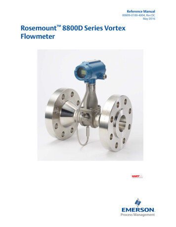
Reference Manual00809-0100-4004, Rev DCTitle PageMay 2016Rosemount 8800D SeriesVortex FlowmeterRead this manual before working with the product. For personal and system safety, and foroptimum product performance, make sure you thoroughly understand the contents beforeinstalling, using, or maintaining this product.The products described in this document are NOT designed for nuclear-qualifiedapplications. Using non-nuclear qualified products in applications that requirenuclear-qualified hardware or products may cause inaccurate readings.For information on Rosemount nuclear-qualified products, contact your local Emerson Process Management Sales Representative.This product is intended to be used as a flowmeter for liquid, gas, or steam applications.Any use other than for which it was intended may result in serious injury or death.Title Pagei
Title PageMay 2016iiReference Manual00809-0100-4004, Rev DCTitle Page
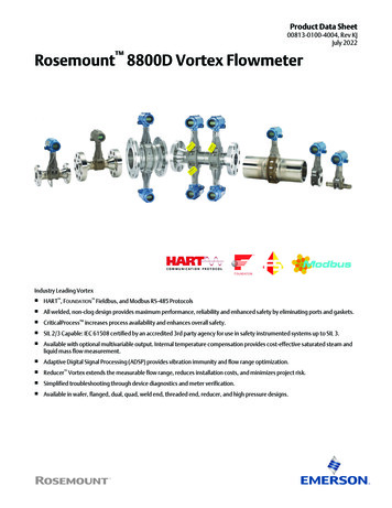
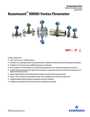
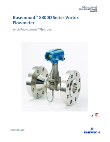
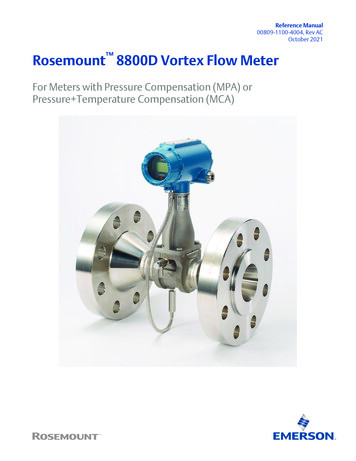
IntroductionReference ManualMay 201600809-0100-4004, Rev DCSection 11.1IntroductionHow to use this manualThis manual provides installation, configuration, operation, troubleshooting, and otherprocedures for the use of the Rosemount 8800D Vortex Flowmeter. For model codeordering information, see the Rosemount 8800D Series Vortex Flowmeter Product DataSheet.Section 2: Configuration contains information on entering and verifying basic configurationparameters.Section 3: Installation contains mechanical and electrical installation instructions.Section 4: Operation contains information on advanced configuration parameters andfunctions that can aid in maintaining the 8800D.Section 5: Troubleshooting provides troubleshooting techniques, diagnostic information,and transmitter verification procedures.Appendix A: Specifications and Reference Data provides reference and specification data.Appendix B: Product Certifications provides specific information for approval codes.Appendix C: Electronics Verification provides a short procedure for verification of electronicoutput to assist in meeting the quality standards for ISO 9001 certified manufacturingprocesses.Appendix D: HART Fast Keys provides command tree, and Fast Key Sequence tables for theField Communicator when used in conjunction with the Rosemount 8800D.1.2Safety messagesProcedures and instructions in this manual may require special precautions to ensure thesafety of the personnel performing the operations. Refer to the safety messages, listed atthe beginning of each section, before performing any operations.1.3System descriptionThe Rosemount 8800D Vortex Flowmeter consists of a meter body and transmitter, andmeasures volumetric flow rate by detecting the vortices created by a fluid passing by theshedder bar.The meter body is installed in-line with process piping. A sensor is located at the end of theshedder bar which creates a sine wave signal due to the passing vortices. The transmittermeasures the frequency of the sine wave and converts it into a flowrate.Introduction1
IntroductionMay 20162Reference Manual00809-0100-4004, Rev DCIntroduction
Reference ManualConfiguration00809-0100-4004, Rev DCSection 2May 2016ConfigurationProcess variables . . . . . . . . . . . . . . . . . . . . . . . . . . . . . . . . . . . . . . . . . . . . . . . . . . . . . . . . . . page 3Basic setup . . . . . . . . . . . . . . . . . . . . . . . . . . . . . . . . . . . . . . . . . . . . . . . . . . . . . . . . . . . . . . . .page 112.1Process variablesFastKeys3, 2, 1Process Variables for the Rosemount 8800D provides the flowmeter output. Whencommissioning a flowmeter, review each process variable, its function and output, and takecorrective action if necessary before using the flowmeter in a process application.2.1.1Primary Variable (PV)FastKeys2, 2, 2, 1The measured value of the variable mapped to the primary variable. This can be eitherProcess Temperature (MTA option only) or Flow. Flow variables are available as mass,volume, corrected volume, or velocity. When bench commissioning, the flow values foreach variable should be zero and the temperature value should be the ambienttemperature.If the units for the flow or temperature variables are not correct, refer to “Process VariableUnits” on page 4. Use the Process Variable Units function to select the units for yourapplication.2.1.2Percent of RangeFastKeys3, 4, 3, 2The primary variable as a percentage of range provides a gauge as to where the measuredflow rate of the meter is within the configured range of the meter. For example, the rangemay be defined as 0 gal/min to 20 gal/min. If the measured flow rate is 10 gal/min, thepercent of range is 50 percent.2.1.3Analog OutputFastKeys3, 4, 3, 1The analog output variable provides the analog value for the primary variable. The analogoutput refers to the industry standard output in the 4–20 mA range. Check the analogoutput value against the actual loop reading given by a multi-meter. If it does not match, a4–20 mA trim is required. See “Analog Trim” on page 51.Configuration3
Reference ManualConfiguration00809-0100-4004, Rev DCMay 20162.1.4Process Variable Units2, 2, 2, 6FastKeysAllows for the viewing and configuration of Process Variable Units such as Volume, Velocity,Mass Flow, Electronics Temperature, Process Density, and Corrected Volume units,including corrected volume Special Units configuration.Volume Flow3, 2, 1FastKeysAllows the user to view the volumetric flow rate value.Volume Flow UnitsFastKeys2, 2, 2, 6, 1Allows the user to select the volumetric flow units from the available list.4gallons per secondimperial gallons per minutegallons per minuteimperial gallons per hourgallons per hourimperial gallons per daygallons per dayliters per secondcubic feet per secondliters per minutecubic feet per minuteliters per hourcubic feet per hourliters per daycubic feet per daycubic meters per secondbarrels per secondcubic meters per minutebarrels per minutecubic meters per hourbarrels per hourcubic meters per daybarrels per daymega cubic meters per dayimperial gallons per secondspecial unitsConfiguration
Reference ManualConfiguration00809-0100-4004, Rev DCMay 2016Corrected Volumetric Flow UnitsFastKeys2,2,2,6,2Allows the user to select the corrected volumetric flow units from the available list.gallons per secondimperial gallons per hourgallons per minuteimperial gallons per daygallons per hourliters per secondgallons per dayliters per minutecubic feet per secondliters per hourstandard cubic feet per minuteliters per daystandard cubic feet per hournormal cubic meters per minutecubic feet per daynormal cubic meters per hourbarrels per secondnormal cubic meters per daybarrels per minutecubic meters per secondbarrels per hourcubic meters per minutebarrels per daycubic meters per hourimperial gallons per secondcubic meters per dayimperial gallons per minutespecial unitsNoteWhen measuring corrected volumetric flow, a base density and process density must beprovided.Mass FlowFastKeys3, 2, 1Allows the user to view the mass flow rate value and units.Configuration5
Reference ManualConfiguration00809-0100-4004, Rev DCMay 2016Mass Flow UnitsFastKeys2, 2, 2, 6, 5Allows the user to select the mass flow units from the available list. (1 STon 2000 lb; 1MetTon 1000 kg)grams per hourpounds per daygrams per minutespecial unitsgrams per secondshort tons per daykilograms per dayshort tons per hourkilograms per hourshort tons per minutekilograms per minutepounds per secondkilograms per secondtons (metric) per daypounds per minutetons (metric) per hourpounds per hourtons (metric) per minuteNoteIf you select a Mass Flow Units option, you must enter process density in your configuration.Velocity FlowFastKeys3, 2, 1Allows the user to view the velocity flow rate value and units.Velocity Flow UnitsFastKeys2, 2, 2, 6, 3Allows the user to select the Velocity Flow Units from the available list.feet per secondmeters per secondVelocity Measurement BaseFastKeys2, 2, 2, 6, 4Determines if the velocity measurement is based on the mating pipe ID or the meter bodyID. This is important for Reducer Vortex Applications.6Configuration
Reference ManualConfiguration00809-0100-4004, Rev DCMay 2016Special UnitsFastKeys2,2,2,7 (Volume)2,2,2,8 (Mass)2,2,2,9 (Corrected Volume)Allows the user to create flow rate units that are not among the standard options.Configuration of a special unit involves entry of these values: base flow unit, base time unit,user defined unit and conversion number. Suppose the user wants the Rosemount 8800D todisplay flow in beer barrels per minute instead of gallons per minute, and one beer barrel isequal to 31 gallons. Base volume unit: gal Base time unit: min User defined unit: br Conversion number: 1/31.0See the specific variables listed below for more information on setting special units.Base Flow UnitFastKeys2,2,2,7,1 (Volume)2,2,2,8,1 (Mass)2,2,2,9,1 (Corrected Volume)The unit from which the conversion is made. Select one of the Field Communicator definedunit options:Volumetric flowMass flowCorrected volume flowU.S. gallongramU.S. gallonliterkilogramliterimperial gallonmetric tonimperial galloncubic meterpoundbarrelbarrelshort tonstandard cubic footcubic footnormal cubic footBase Time UnitFastKeys2,2,2,7,4 (Volume)2,2,2,8,4 (Mass)2,2,2,9,4 (Corrected Volume)Provides the time unit from which to calculate the special units. For example, if the specialunit is a volume per minute, select minutes. Choose from the following units:Configuration Seconds (s) Minutes (min) Hours (h) Days (d)7
Reference ManualConfiguration00809-0100-4004, Rev DCMay 2016Special Flow UnitFastKeys2,2,2,7,5 (Volume)2,2,2,8,5 (Mass)2,2,2,9,5 (Corrected Volume)A user created custom flow unit. The special unit is limited to four characters. The FieldCommunicator indicates the special unit with SPCL. The LCD display will display the actualfour character user defined special unit.Conversion NumberFastKeys2,2,2,7,2 (Volume)2,2,2,8,2 (Mass)2,2,2,9,2 (Corrected Volume)Used to relate base units to special units. For a straight conversion of volume units from oneto another, the conversion number is the number of base units in the new unit.For example, if it is desired to convert from gallons to beer barrels there are 31 gallons in abeer barrel. The conversion equation is as follows (where beer barrels is the new volumeunit):1 gallon 0.032258 bbl.TotalFastKeys2, 2, 4, 3, 1Provides the output reading of the totalizer. Its value is the amount of liquid or gas that haspassed through the flowmeter since the totalizer was last reset.Totalizer ControlFastKeys2, 2, 4, 3, 2Allows the totalizer to be started, stopped, or reset.Start—Starts the totalizer counting from its current value.Stop—Interrupts the totalizer count until it is restarted again. This feature is often usedduring pipe cleaning or other maintenance operations.Reset—Returns the totalizer value to zero. If the totalizer was running, it will continue to runstarting at zero.8Configuration
Reference ManualConfiguration00809-0100-4004, Rev DCMay 2016Totalizer ConfigFastKeys2, 2, 4, 3, 3Used to configure the flow parameter (volume, mass, velocity, or corrected volume flow)that will be totaled.NoteThe totalizer value is saved in the non-volatile memory of the electronics every threeseconds. Should power to the transmitter be interrupted, the totalizer value will start at thelast saved value when the power is re-applied.NoteChanges that affect the density, density ratio, or compensated K-Factor will affect thetotalizer value being calculated. These changes will not cause the existing totalizer value tobe recalculated.NoteIn order to totalize in compensated mass flow or compensated corrected volume flow, forunits with the MTA option only, set pulse output to match the totalizer configuration even ifthe pulse output was not ordered.Pulse FrequencyFastKeys3, 2, 5, 3Allows the user to view the pulse output frequency value. To configure the pulse output,refer to the section on pulse output found on page 54.Shedding FrequencyFastKeys3, 2, 5, 1Allows the user to view the shedding frequency directly off of the sensor.Electronics TemperatureFastKeys3, 2, 6, 2Allows the user to view the Electronics Temperature value and units.Electronics Temperature UnitsFastKeys2, 2, 2, 6, 6 (without MTA)2, 2, 2, 6, 7 (with MTA)Allows the user to select the Electronics Temperature Units from the available list.Configuration deg C deg F9
Reference ManualConfiguration00809-0100-4004, Rev DCMay 2016Calculated Process DensityFastKeys3, 2, 1Allows the user to view the calculated process density value when the transmitter isconfigured for temperature compensated steam or temperature compensated liquidapplications.Process Density UnitsFastKeys2, 2, 2, 6, 7 (without MTA)2, 2, 2, 6, 8 (with MTA)Allows the user to configure the Process Density Units from the available list. g/Cucm (cm3) g/L kg/Cum (m3) lb/Cuft (ft3) lb/Cuin (in3)Process TemperatureFastKeys3, 2, 1Allows the user to view the Process Temperature value when the transmitter has thetemperature sensor option, MTA.Process Temperature UnitsFastKeys2, 2, 2, 6, 6 (only with MTA)Allows the user to configure the units for the process temperature from the available list. deg C deg F deg R KelvinTemperature Sensor Failure ModeFastKeys2, 2, 1, 3, 1Allows the user to configure the temperature sensor failure mode. In the event that thetemperature sensor fails, the vortex can go either into an alarm output mode, or continueto operate normally using the Fixed Process Temperature value. See Fixed ProcessTemperature on page 12. This mode is only relevant with the MTA option.NoteIf the Primary Variable is set to Process Temperature and there is an error, the output willalways go to alarm and this setting will be ignored.10Configuration
Reference ManualConfiguration00809-0100-4004, Rev DC2.2May 2016Basic setupFastKeys2, 1, 1, 1The Rosemount 8800D must be configured for certain basic variables in order to beoperational. In most cases, all of these variables are pre-configured at the factory.Configuration may be required if your Rosemount 8800D is not configured or if theconfiguration variables need revision. The basic setup wizard will take you through all thesteps required to set up the Rosemount Vortex meter for basic operation.The remainder of this section contains details about how to enter basic configurationparameters in order to manually configure the Rosemount 8800D.2.2.1TagFastKeys2, 2, Device Information, 1, 1The quickest way to identify and distinguish between flowmeters. Flowmeters can betagged according to the requirements of your application. The tag may be up to eightcharacters long. Long Tag is available for HART 7 and allows for up to 32 characters.2.2.2Long TagFastKeys2,2,Device Information,1,2Available for HART 7 and allows for up to 32 characters.2.2.3Process configurationThe flowmeter can be used for liquid or gas/steam applications, but it must be configuredspecifically for the application. If the flowmeter is not configured for the proper process,readings will be inaccurate. Select the appropriate process configuration parameters foryour application:Transmitter ModeFastKeys2, 2, 1, 1, 1For units with an integral temperature sensor, the temperature sensor can be activatedhere.Without Temperature SensorWith Temperature SensorSet Process FluidFastKeys2, 2, 1, 1, 3Select the fluid type—either Liquid, Gas/Steam, Tcomp Sat Steam, or Tcomp Liquids. TcompSat Steam and Tcomp Liquids require the MTA Option and provide dynamic densitycompensation based on the process temperature reading.Configuration11
Reference ManualConfiguration0080
The Rosemount 8800D Vortex Flowmeter consists of a meter body and transmitter, and measures volumetric flow rate by detecting the vortices created by a fluid passing by the shedder bar. The meter body is installed in-line with process piping. A sensor is located at the end of the