Transcription
Component Maintenance Manual(CMM)For Hawker Valve RegulatedSealed Lead Acid Aircraft BatteriesEnerSys Energy Products Inc.617 North Ridgeview DriveWarrensburg, MO 64093, USATel. (800) 964-2837Fax (800) 283-2948www.enersys.com/defenseDocument Number 2602-0018Rev. 5Date: 3/01/13Page 1 of 19
Contents1Scope . 32Safety Notes . 33General Maintenance Notes . 34Introduction . 45Battery Description . 46Specifications . 57Receipt of Battery & Acceptance Checks . 68Storage . 69Commissioning Procedures and Initial Testing after Storage . 810Routine Maintenance. 911Charging Procedure . 1212Deep Discharge recovery / Unscheduled Removal from Aircraft . 1313Capacity Testing . 1414Rejection Procedure . 1515Transportation . 1516Master Record Index . 1517Disposal. 16Appendix A: Battery Commissioning Flowchart . 17Appendix B: Battery Maintenance Flow Chart . 18Record of Revisions . 19Document Number 2602-0018Rev. 5Date: 3/01/13Page 2 of 19
1 Scope1.1This manual covers the storage, servicing, maintenance, replacement,repair and disposal of Hawker VRLA AGM aircraft batteriesmanufactured by EnerSys Energy Products Inc. under Parts ManufacturerApproval No. PQ3810CE.1.2A complete list of batteries manufactured under Type Certificates can befound at: http://www.enersys.com/defense/pdfs/MSB Certs list.pdf2 Safety Notes2.1Short circuit current for a Hawker aircraft battery can exceed 2000 amps.The following steps must be taken for safety.2.2Use only insulated tools when working on and around the battery.2.3Remove all metal jewelry including necklaces, rings, watches and beltswith large buckles.2.4Do not smoke, cause a spark or use an open flame near a battery.2.5Always ensure that the battery lid is securely fitted prior to charging.3 General Maintenance Notes3.1Use a Fluke Digital Voltmeter Series 70, or equivalent, to perform allvoltage measurements.3.2This manual covers both 24Volt and 12Volt batteries. Voltage valueslisted in this manual are given for 24Volt batteries with the applicable12Volt battery value shown in parentheses after the 24Volt value.3.3Discharges for capacity testing should be stopped at 60 minutes or whenthe terminal voltage reaches the value published for the rated capacity.This prevents excessive working of the battery and prolongs its life.3.4Only charge the battery in a well-ventilated air space. See section 11 fordetails concerning charging.Document Number 2602-0018Rev. 5Date: 3/01/13Page 3 of 19
4 Introduction4.1Hawker VRLA AGM batteries are designed as valve regulated,recombinant systems and classified as non-spillable and unrestricted fortransportation per US D.O.T. Regulation 49 C.F.R. Section 173.159 parad. when correctly packaged. As a result, the battery can be oriented andoperated in any attitude or position without spillage of electrolyte under fullaerobatic conditions.4.2The battery is maintenance free with respect to electrolyte replenishment.Under no circumstances should any attempt be made to introduce anysubstances, e.g. acid, distilled water or alkali to the battery.5 Battery Description5.1The 24Volt Hawker VRLA AGM aircraft batteries covered by thismaintenance manual consist of two 12Volt sealed monoblocs connectedin series, enclosed in a polyester bonded fiber glass or metal case, whichincorporates the battery main terminal connector.5.2Each 12Volt monobloc consists of six 2Volt cells internally connected inseries to make a 12Volt block. The individual 2Volt cells are notreplaceable. The cells within the monoblocs are interconnected withthrough-the-partition-wall weld connections.5.3The cells are manufactured with proprietary VRLA AGM technology thatcan deliver high performance engine start capability in excess of 50C1Amps at normal temperature and superb durability under emergency loadconditions.5.4Thin fiberglass separators inter-space the positive and negative plates.The tightly packed plates and separator form a compressed and ruggedconstruction, which enhances the battery’s resilience to vibration.5.5Batteries can be configured with or without external vents depending uponthe installation requirements. The fiberglass container does not alwayshave vents installed.Document Number 2602-0018Rev. 5Date: 3/01/13Page 4 of 19
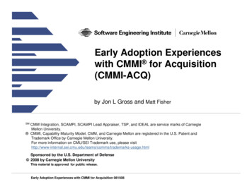
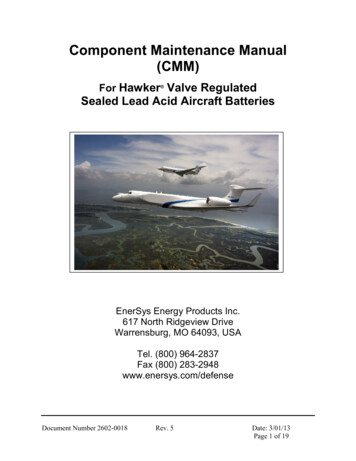
6 Specifications6.1Capacity6.1.1 The capacity of Hawker VRLA AGM aircraft batteries is stated in Amphours (Ah) at the one hour rate. For example an 18Ah battery willprovide 18Amps for one hour to the end voltage shown on the nameplate for the Amp-Hour rating.6.1.2 Unless otherwise directed by the aircraft manufacturer, 80% of ratedcapacity is the accepted minimum requirement for flight.6.2Temperature Effects6.2.1 The ideal ambient temperature for battery operation is 23ºC to 25ºC.Long term exposure to temperature above 30ºC will shorten the life ofthe battery.6.2.2 Battery temperatures below 25 C reduce performance, which causes areduction in capacity. However, this is not a permanent condition; thecapacity will be restored as the temperature rises. Long term exposureto low temperature will not damage the battery.6.3State of Charge (see Figure 1, page 7)6.3.1 The open circuit voltage (OCV) of the battery can be used as a guideto the state of charge (SOC) of the battery. The graph in Figure 1shows the relationship between open-circuit voltage and the state ofcharge. The Red Line shows the SOC for the OCV after 24 hours ormore after charge. The Blue Line shows the SOC for the OCV 4 hoursafter a charge.6.3.2 The state of charge is not the same as available capacity. A battery atend-of-life and fully charged will have an OCV of approximately 26.0V,but will have an available capacity of 80% of rated capacity.Document Number 2602-0018Rev. 5Date: 3/01/13Page 5 of 19
7 Receipt of Battery & Acceptance Checks7.1All batteries ship from the manufacturer in the fully charged condition; thedate of the latest charge is marked on the outer packaging and on thebattery instruction label.7.2If the battery is received within three months of the latest charge, the onlyacceptance check required immediately upon receipt is inspection of thebox for damage during shipping. The battery does not have to beunpacked.7.2.1If the box is damaged from shipping, unpack the battery to inspectfor any damage. If damage to the battery is found, contact theshipper immediately.7.3If the battery is received 4 months or longer after the latest charge, unpackthe battery to perform a voltage check in accordance with Section 9.7.4The battery label 97.4.10Type of battery (i.e. lead acid – aerobatic)Manufacturer’s nameProduct numberSerial numberManufacturing date codeTerminal polarityNominal battery voltageRated capacitySafety instructionsDisposal instructions8 Storage8.1The battery should be stored, fully charged, in a dry environment at orbelow 25ºC. Storing a battery at a temperature above 25 C acceleratesthe aging process reducing service life.8.2Every year, inspect a stored battery and check the OCV. If the OCV fallsbelow 25.5V administer a boost charge per Section 11.8.3The battery can be stored for up to two (2) years at 25 C or below with noinspection or boost charge. After two (2) years a boost charge must beadministered per Section 11 regardless of OCV.Document Number 2602-0018Rev. 5Date: 3/01/13Page 6 of 19
8.4A battery may be stored up to five (5) years without degradation ofperformance provided that an inspection and open circuit voltage check isconducted every year and boost charges are administered as dictatedabove.8.5If a battery stored in temperatures in excess of 25ºC, it should beinspected every six months and given a boost charge per Section 11 whenthe OCV falls below 25.5V.8.6Batteries returned to storage following in-service use, must be fullyrecharged and, ideally, packed in original packaging.Figure 1: State of Charge (SOC) as a function of Open Circuit Voltage (OCV)Document Number 2602-0018Rev. 5Date: 3/01/13Page 7 of 19
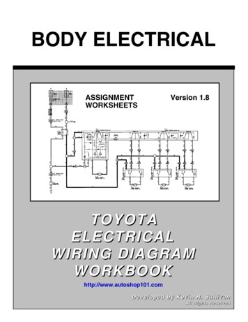
9 Commissioning Procedures and Initial Testing after Storage(Refer to Battery Commissioning Flowchart Appendix A)9.1Visually inspect the exterior of the battery casing for signs of damage andcracks. Examine the battery terminal and heater connector, if fitted, forsigns of damage, corrosion, and water/dirt ingress; clean as necessary.9.2Measure the open cell voltage (OCV)9.3If OCV equals 25.50 (12.75) Volts or greater, the capacity is at least 80%and the battery can be issued for service.9.4If OCV is less than 25.50 (12.75) Volts and greater than 25.30 (12.65)Volts the battery needs to be charged before placing it into service.9.4.1 Follow Section 11 for charging procedures.9.4.2 If the OCV equals 25.50 (12.75) Volts or greater after charging, thebattery can be issued for service.9.5If OCV equals 25.30Volts (12.65) Volts or less the battery needs to becharged and given a capacity test before placing it into service.9.5.1 Follow Section 11 for charging procedures.9.5.2 Follow Section 13 for capacity testing procedures.9.5.3 If the battery fails to make 80% capacity after charging and acapacity test, it can be recharged and tested a second time.9.5.4 If the battery achieves at least 80% capacity:9.5.4.1 Record the capacity and date of test.9.5.4.2 Issue the battery for service.9.5.5 If the battery fails to achieve 80% capacity after two (2) charge andcapacity tests, reject the battery per Section 14.9.6Batteries with and OCV of 25.50 (12.75) Volts or less should never beinstalled in an aircraft.Document Number 2602-0018Rev. 5Date: 3/01/13Page 8 of 19
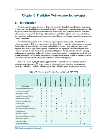
10 Routine Maintenance(Refer to Battery Maintenance Flowchart Appendix B)10.1The maintenance schedule is shown in tabular form in Table 10.1.10.2The maintenance schedule is shown in text form below.10.2.1 For Saab 340 & Jetstream 41 aircraft and Bell 206 helicopters thefirst routine maintenance check occurs at 12 months (365) 30days or 3000 300 hours, whichever comes first.10.2.2 For all other aircraft and helicopters not covered in 10.2.1 the firstroutine maintenance check occurs at 18 months (548) 45 daysor 4500 450 hours, whichever comes first.10.2.3 Subsequent maintenance checks occur at the following intervalsdepending on the results of the capacity test. These intervalsapply to all aircraft and helicopters.10.2.3.1When the measured capacity equals 90% or greater,the next check occurs in 6 months (180) 15 days or1500 100 hours whichever comes first.10.2.3.2When the measured capacity is between 81% and90%, the next check occurs in 3 months (90) 10 daysor 750 50 hours whichever comes first.10.2.4 The above intervals are the minimum recommended servicingintervals. User or application specific service intervals can bedeveloped, but they must be shorter in time than the intervalsshown above.Document Number 2602-0018Rev. 5Date: 3/01/13Page 9 of 19
Table 10.1: Maintenance IntervalsOff-Aircraft CapacityChecks12 Month Initial Check18 Month Initial Check6 Month Check Interval(extension, after the initialcheck)ApplicabilityCompliance ScheduleSaab 340,Jetstream 41 Aircraft,Bell 206 HelicoptersAll aircraft/helicoptersnot identified under the12 Month initial checkAll AircraftAt 365 30 days, or 3000 300 hours(whichever comes first), after theinstallation of a new batteryAt 548 45 days, or 4500 450 hours(whichever comes first), after theinstallation of a new battery.When measured capacity is greaterthan 90% of new capacity, the nextcapacity check shall be at 180 15days, or 1500 100 hour intervalsfollowing the initial battery check.When measured capacity is between81% and 90% of new capacity, thenext capacity check shall be at 90 10days, or 750 50 hour intervalsfollowing the initial battery check.3 Month Check Interval(extension, after the initialcheck)All Aircraft10.3Visually inspect the exterior of the battery casing for signs of damage andcracks. Examine the battery terminal and heater connector, if fitted, forsigns of damage, corrosion, and water/dirt ingress; clean as necessary.Always ensure that the battery lid is securely fitted prior to charging, (whenapplicable).10.4Measure and record the OCV using a digital multi-meter. Measure andrecord the weight of the battery.10.4.1 If the OCV measures 25.50 (12.75) Volts or less, charge thebattery per Section 11. Otherwise, test the battery in the “asfound” condition.10.5Perform a capacity test per Section 13.10.6If the result of the capacity test is 80% or less:10.6.1 If the battery has been tested once, it can be charged and tested asecond time.10.6.1.1 Recharge per section 11.Document Number 2602-0018Rev. 5Date: 3/01/13Page 10 of 19
10.6.1.2 Retest per section 13.10.6.2 If the battery fails to make 80% capacity after two (2) capacitytests reject the battery per Section 14.10.7If the result of the capacity test is greater than 80% but less than 90%:10.7.1 Record the capacity and date of test on the battery label.10.7.2 Ensure the battery is clean and return the battery to service.10.7.3 Schedule the next routine maintenance check per 10.2.3.2.10.7.4 Issue the battery.10.8If the result of the capacity test is greater than or equal to 90%:10.8.1 Record the capacity and date of test on the battery label.10.8.2 Ensure the battery is clean and return the battery to service.10.8.3 Schedule the next routine maintenance check per 10.2.3.1.10.8.4 Issue the battery.Document Number 2602-0018Rev. 5Date: 3/01/13Page 11 of 19
11 Charging Procedure11.1This manual only covers Constant Voltage (CV) charging because CVcharging is the preferred method. Every effort should be made to chargeHawker VRLA AGM batteries with constant voltage. If constant currentcharging is the only available option, please contact EnerSys TechnicalSupport for guidance.11.2Charging should be performed in the battery work shop where the ambienttemperature is maintained between 20ºC and 30ºC. The battery can becharged outside this temperature window if a temperature compensatedcharger is used.11.3Charge the battery at a constant voltage of 29.0Volts (14.50Volts) with acharger capable of delivering a minimum of 10Amps. Charge timedepends on the rated capacity of the battery and the maximum currentavailable from the charger. Use Table 11.3 for guidance.11.3.1 The higher current limit available on the charger, the faster thebattery will charge.11.3.2 After charge completion allow the battery to rest open circuit for 4hours before performing a capacity test or measuring the OCV.Table 11.3: Constant Voltage Charge ParametersMin Current Available fromthe Charger 10AmpsMin Current Available fromthe Charger 20AmpsMin Current Available from theCharger 30Amps or moreCharge TimeCharge TimeCharge Time10 Amp-hour3 hours2 hours1 hour18 Amp-hour4 hours3 hours2 hours22 Amp-hour6 hours5 hours2 hours25 Amp-hour6 hours5 hours4 hours40 Amp-hour8 hours7 hours6 hours43 Amp-hour9 hours8 hours7 hoursBattery RatingDocument Number 2602-0018Rev. 5Date: 3/01/13Page 12 of 19
12 Deep Discharge recovery / Unscheduled Removal from Aircraft12.1Discharging a Hawker battery below 18.0Volts (9.0Volts) under load isconsidered abuse and voids the warranty.12.2A battery is considered deeply discharged when the OCV equals less than20.0Volts (10.0Volts).12.3The VRLA AGM technology used in Hawker batteries allows recoveryfrom deep discharge where a normal VRLA battery may not berecoverable. The most common cause for a deeply discharged battery isa low current drain for an extended period of time.12.4If a battery is inadvertently deeply discharged below 18.0Volts (9.0Volts),it should be removed from the aircraft immediately for recharge.12.5Charge the battery following the procedures in Section 11.12.6Perform a capacity test following the procedures in Section 13.12.7Even though a deeply discharged battery can be recovered; it is stronglyrecommended that deep discharging of batteries be prevented.12.8Deep discharges usually result from an unknown parasitic load on thebattery that slowly drains the battery over a long period of time. If thebattery suffers a deep discharge, inspect the electrical system for aparasitic load.Document Number 2602-0018Rev. 5Date: 3/01/13Page 13 of 19
13 Capacity Testing13.1Capacity testing is performed by discharging the battery with a constantcurrent load at the one- hour rate and measuring the time required (inminutes) to reach the cut off voltage.13.2Discharge the battery at the appropriate constant current value found intable 13.1 below.Table 13.1: Capacity Test Current ValuesBattery RatingDischarge Current10 Amp-hour10 Amps18 Amp-hour18 Amps22 Amp-hour22 Amps25 Amp-hour25 Amps40 Amp-hour40 Amps43 Amp-hour43 Amps13.3End the test when the terminal voltage reaches the voltage value on thename plate used for the Amp-Hour rating or when the run time reaches 60minutes duration, whichever occurs first.13.4Calculate the capacity of the battery using this equation:Capacity% (Run Time / 60) X 10013.5The minimum allowable capacity for flight is 80% or 48 minutes.13.6Recharge the battery per Section 11.Document Number 2602-0018Rev. 5Date: 3/01/13Page 14 of 19
14 Rejection Procedure14.1If the battery fails to attain a 48 minute run time (80% capacity) after twodischarge tests and has been in service for more than two (2) years, itshould be considered non-serviceable. Recycle or otherwise properlydisposed of battery. Refer to section 19 for disposal options.14.2If the battery fails to attain a 48 minute run time (80% capacity) after twodischarge tests and has been in service for less than two (2) years,contact your distributor for further instructions.14.3If the battery is eligible for re-blocking contact your distributor for specificre-blocking instructions.15 Transportation15.1Hawker aircraft batteries are classified as non-spillable and exempt fromhazardous goods regulations in accordance with the following governingbodies when securely packed and protected against short circuits.15.1.1 US Department of Transportation – 49 CFR Section 173.159Section d.15.1.2 ICAO / IATA Packing Instruction 806, Special Provision A67.15.1.3 IMDG Class 8, UN ID 2800 exemption for non-spillable batteries.16 Master Record Index16.1A Master Record Index must be kept for each individual battery includingthe following data points:16.1.116.1.216.1.316.1.416.1.5Battery part number and serial numberDate of receipt from manufacturerDate of commissionDate of installation on aircraftDate and results of periodic routine maintenance or unscheduledmaintenance16.1.6 Date of battery returned to storage16.1.7 Date of any failure16.1.8 Date of any returns to manufacturerDocument Number 2602-0018Rev. 5Date: 3/01/13Page 15 of 19
16.1.9 OCV prior to any capacity test16.1.10 Serial number of re-blocking kit16.1.11 Date of re-blocking16.2The record index will provide an indication as to the status of the battery,its life in service, and is essential for warranty claim consideration.17 DisposalDispose of the battery in accordance with local regulations for lead acid batteries.Never put a battery in a landfill. If in doubt local distributor or EnerSys at:EnerSys Energy Products Inc.617 N. Ridgeview DriveWarrensburg, MO 64093USATel. (800) 964-2837Fax (800) 283-2948EnerSys Ltd.Stephenson StreetNewport, GwentUKTel. 44 1633 277673FAX 44 1633 281787A control of Substances Hazardous to Health statement and Material Safety Data Sheetare available at: cument Number 2602-0018Rev. 5Date: 3/01/13Page 16 of 19
Appendix A: Battery Commissioning FlowchartDocument Number 2602-0018Rev. 5Date: 3/01/13Page 17 of 19
Appendix B: Battery Maintenance Flow ChartDocument Number 2602-0018Rev. 5Date: 3/01/13Page 18 of 19
Record of RevisionsRevisionNumber012345Description of ChangesNew Document – Original IssueDocument Update – amended CC ChargecurrentsAmended ratings for 37Ah battery to 40AhAddition of Maintenance Interval GuidelinesDocument Update – revised charging andcapacity test information, amended reblock kitnumbers. Revision Never IssuedComplete re-write – removed CC charging andreblocking instructionsDate10/20/0007/12/01ApprovalDon NissankaRobert Griffiths01/10/0210/20/046/17/10Robert GriffithsRobert GriffithsRobert Griffiths/Frank Metzger03/08/13Robert Griffiths / KenHillNOTE: The current revision of this manual is at http://www.enersys.com/defenseDocument Number 2602-0018Rev. 5Date: 3/01/13Page 19 of 19
Document Number 2602-0018 Rev. 5 Date: 3/01/13 Page 3 of 19 1 Scope 1.1 This manual