Transcription
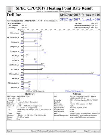
POLARIZATION EXTINCTION RATIO METERFeatures: Measures up to 40 dB extinction ratios (over specificwavelength ranges)Built in USB Communications InterfaceWide wavelength range: 400 to 1000 nm for visible range;850 to 1650 nm and 1800 to 2400 nm for IR0.01 dB resolution in ER and 0.3 resolution in angleAccuracy in ER is 1 dB, in angle is 0.5 Measures up to 2 Watts CW input powerRugged and compact designLogging mode for continuous measurementInterchangeable connector adaptorsLOW COST!Applications: Fiber optic component manufacturingAutomated alignmentQuality control and measurementProduct developmentComponent or system troubleshootingFiber Optic PolarizationExtinction Ratio MeterProduct Description:OZ Optics’ Polarization Extinction Ratio Meter allows one to quicklymeasure the output extinction ratio of light from a fiber. A rotatingpolarizer measures the extinction ratio and the orientation of thetransmission axis with respect to the key on the connector. As anoption, neutral density filters can be added to the Extinction RatioMeter, to extend the maximum power range. These filters can be easilyinserted and removed, without disturbing your setup. These filters allowpower levels up to 2 Watts to be measured.The meter operates in several modes. In real time mode, the metergives the extinction ratio and alignment. In logging mode, the metergives the worst case extinction ratio over a given time span. This modeis ideal for QA measurements.In addition the meter can provide a relative power readout, proportionalto the input power in dB. This readout is updated at up to 650 times persecond. The computer interface allows the unit to be used withcomputer control units, for alignment purposes. The combination ofpolarization and relative power functions allows the unit to be used forcomplete auto-alignment of polarization maintaining components.DTS0067OZ Optics reserves the right to change any specifications without prior notice.3 March 20221
Ordering Information For Standard Parts:Bar CodePart NumberDescriptionMeters11998ER-100-1290/1650-ER 40*Fiber Optic Polarization Extinction Ratio Meter for wavelengths from 1290 nm to 1650 nm.ER 40 dB. Receptacle is not included.11997ER-100-IR*Fiber Optic Polarization Extinction Ratio Meter for wavelengths from 850 nm to 1650 nm.ER 30 dB for wavelengths from 850 nm to 1290 nm and ER 35 dB for wavelengths longerthan 1290 nm. Receptacle is not included.12866ER-100-VIS*Fiber Optic Polarization Extinction Ratio Meter for wavelengths from 400 nm to 1000 nm.ER 30 dB over the wavelength range. Receptacle is not included.Receptacles13440ER-23-1290/1650-ER 40Super and Ultra FC removable receptacle for ER Meter for wavelengths from 1290 nm to 1650 nmachieving up to 40 dB extinction ratio13441ER-23A-1290/1650-ER 40Angled FC removable receptacle for ER Meter for wavelengths from 1290 nm to 1650 nmachieving up to 40 dB extinction ratio8705ER-23-IRSuper and Ultra FC removable receptacle for ER Meter for wavelengths from 850 nm to1650 nm achieving up to 30 dB extinction ratio7525ER-23A-IRAngled FC removable receptacle for ER Meter for wavelengths from 850 nm to 1650 nmachieving up to 30 dB extinction ratio7528ER-2SC-IRSC removable receptacle for ER Meter for wavelengths from 850 nm to 1650 nm achieving upto 30 dB extinction ratio8874ER-2LC-IRLC removable receptacle for ER Meter for wavelengths from 850 nm to 1650 nm achieving upto 30 dB extinction ratio7526ER-28-IRST removable receptacle for ER Meter for wavelengths from 850 nm to 1650 nm achieving upto 30 dB extinction ratio13165ER-23-VISSuper and Ultra FC/PC removable receptacle for ER meter optimized for 400-1000 nm14320ER-23A-VISFC/APC removable receptacle for ER meter optimized for 400-1000 nmAttenuators10626ER-ND-10-450/170010 dB attenuator for ER Meter for wavelengths from 450 nm to 1700 nm8704ER-ND-20-IR20 dB attenuator for ER Meter for wavelengths from 850 nm to 1650 nm9471ER-ND-35-1250/165035 dB attenuator for ER Meter for wavelengths from 1250 nm to 1650 nmSources1550 nm, 1 mW Polarized Fiber Optic Source with a Super/Ultra FC/PC receptacle androtatable polarizer achieving up to 40 dB extinction ratio (Refer to Data Sheet titled PolarizedFiber Optic Source for further information).11378PFOSS-02-3-1550-1-ER 4013507PFOSS-02-3-1310-1-ER 4013509PFOSS-02-3A-1310-1-ER 4013508PFOSS-02-3A-1550-1-ER 4013390Master patchcord, Ultra FC/PC to Ultra FC/PC, 8/125 um PM 1550 nm fiber, 0.9 mmPMJ-3U3U-1550-8/125-1-1-1-ER 30-G OD jacketed, 1 meter long with connectors aligned and locked to the slow axis.ER 30 dB minimum13386PMJ-3A3A-1550-8/125-1-1-1-ER 30-G1310 nm, 1 mW Polarized Fiber Optic Source with a Super/Ultra FC/PC receptacle androtatable polarizer achieving up to 40 dB extinction ratio1310 nm, 1 mW Polarized Fiber Optic Source with angled FC/PC receptacle and rotatablepolarizer achieving up to 40 dB extinction ratio1550 nm, 1 mW Polarized Fiber Optic Source with angled FC/PC receptacle and rotatablepolarizer achieving up to 40 dB extinction ratioReference PatchcordsMaster patchcord, angled FC/PC to angled FC/PC, 8/125 um PM 1550 nm fiber, 0.9 mmOD jacketed, 1 meter long with connectors aligned and locked to the slow axis.ER 30 dB minimumNote: This is only a partial list of standard parts offered by OZ Optics. Other parts are available as standard products.2
Standard Product Specifications1:ER-100-VISER-100-1290/1650-ER 40ER-100-IRER-100-1800/2400Bar Code NumberPart Number12866119981199742850Wavelength Range400 nm to 1000 nm21290 nm to 1650 nm850 nm to 1650 nm1800 nm to 2400 nmExtinction Ratio Range30 dB40dB for 1290 nm to1650 nm30 dB for 850 nm to 1290 nm35 dB for 1290 nm to 1650 nm30 dBDynamic Range40 dB47 dBExtinction Ratio Accuracy 1dBExtinction Ratio Resolution0.01dBAngular Accuracy3 0.5 degreesAngular Resolution0.3 degreesUpdate Rate (Extinction Ratio)2.7 HzUpdate Rate (Relative Power)650 HzInput Optical Power450 µW to 1.0 mWCommunication InterfaceUSBInput Supply VoltageUniversal 50/60 Hz 110/220V AC/DC adapterDimensions (with protective boot)65 x 90 x 184 mm (2.5 x 3.5 x 7.25 inches)Weight (with protective boot)0.48 kg (1.06 lb)Operating Temperature-10 to 50 C (14 to 122 F)Storage Temperature-30 to 60 C (-22 to 140 F)Storage Humidity 90% RH non condensingStandardCSA-C22.2 NO. 61010-1-12*Certifications35 dBUL 61010-1CEDescriptionSafety requirements for electrical equipment for measurement, control, and laboratory use Part 1: General requirements - Third Edition; Update No. 1: July 2015; Update No. 2: April 2016UL Standard for Safety Electrical Equipment For Measurement, Control, and Laboratory Use;Part 1: General Requirements - Third Edition; Including Revisions through July 15, 2015Certifies the product meets all EU health, safety and environment requirements including the latestRoHS & REACH compliance, which ensures consumer safety1 Tested at 23 C 2 C with a 1550 nm linearly polarized source plus a master 1550 nm polarization maintaining patchcord, after a 30 minute warm-up period.2 Dependent on receptacle used, by default the receptacle is aligned at 780 nm and the lens is coated with MgF2 on both surfaces.3 For FC style connectors with high tolerance keyway.4 Without attenuator. Higher powers can be measured with an attenuator. When ordering an attenuator with 20 dB attenuation, the wavelength should be specified. Note:Exposing the detector to power higher than 17 dBm (50 mW) without attenuator for a short period of time (3 minutes) can damage the detector.Ordering Examples For Standard Parts:A customer in Europe needs an Extinction Ratio Meter to measure the polarization properties of pigtailed laser diodes, to confirm thatthe polarization extinction ratio exceeds 30 dB. The lasers are 1550 nm lasers, with output power between 5 and 10 mW. The fibersare terminated with either Super FC/PC, or with FC/APC connectors. The customer also wants a source and reference patchcord forcomparison. The following equipment will be needed:Bar CodePart NumberDescription11998ER-100-1290/1650-ER 40*Fiber Optic Polarization Extinction Ratio Meter for wavelengths from 1290 nm to 1650 nm.ER 40 dB, without receptacle13440ER-23-1290/1650-ER 40Super and Ultra FC removable receptacle for ER Meter for wavelengths from 1290 nm to1650 nm achieving up to 40 dB Extinction Ratio13441ER-23A-1290/1650-ER 40Angled FC removable receptacle for ER Meter for wavelengths from 1290 nm to 1650 nmachieving up to 40 dB Extinction Ratio10626ER-ND-10-450/170010 dB attenuator for ER Meter for wavelengths from 450 nm to 1700 nm11378PFOSS-02-3-1550-1-ER 401550 nm, 1 mW Polarized Fiber Optic Source with a Super/Ultra FC/PC receptacle andRotatable polarizer achieving up to 40 dB Extinction Ratio (Refer to data sheet titledPolarized Fiber Optic Source for further information).13390PMJ-3U3U-1550-8/125-1-1-1-ER 30-GMaster patchcord, Ultra FC/PC to Ultra FC/PC, 8/125 um PM 1550 nm fiber, 0.9 mm ODjacketed, 1 meter long with connectors aligned and locked to the slow axis.ER 30 dB minimum13386PMJ-3A3A-1550-8/125-1-1-1-ER 30-GMaster patchcord, angled FC/PC to angled FC/PC, 8/125 um PM 1550 nm fiber, 0.9 mm ODjacketed, 1 meter long with connectors aligned and locked to the slow axis.ER 30 dB minimum3
Ordering Information For Custom Parts:OZ Optics welcomes the opportunity to provide custom designed products to meet your application needs. As with most manufacturers,customized products do take additional effort so please expect some differences in the pricing compared to our standard parts list.In particular, we will need additional time to prepare a comprehensive quotation, and lead times will be longer than normal. In most casesnon-recurring engineering (NRE) charges, lot charges, and a 1 piece minimum order will be necessary. These points will be carefullyexplained in your quotation, so your decision will be as well-informed as possible. We strongly recommend buying our standard products.Questionnaire For Custom Parts:1)2)3)What is your application?Will you be using the device at a specific wavelength?What is the maximum extinction ratio that you will need tomeasure?4)5)6)7)Do you require external control from a computer?What type of computer interface do you require?What is the maximum power level that you will be using?What type of connector will you be using?DescriptionP Attenuation Level: 10 dB, 20 dB, 30 dB or 35 dBNote: For attenuations over 20dB, specify thewavelength in nmW Wavelength Range (in nm) VIS for 400-1000 nmExtinction Ratio Meter:Part NumberER-100-WIR for 850-1650 nm1800/2400 for 1800-2400 nmNote: If an ER of 40dB is required then specify either980/1060 or 1290/1650 for the wavelength, and add“-ER 40” to the part number. ER 40 dB is onlyachieved on IR models over 980 to 1060 nm, and1290 to 1650 nm wavelength ranges.X Connector Code: 3A Angled NTT-FC/PC8 AT&T-STE E2000SC SCSCA Angled SCLC LCLCA Angled LCMU MU2.5U Universal adaptor for2.5 mm diameter ferrules1.25U Universal adaptor for1.25 mm diameter ferrulesConsult factory for special connector and ferruleadaptors.Attenuators:Connector Adaptors:ER-ND-P-WER-2X-WW Wavelength Range in nm:VIS for 400-1000 nmIR for 850-1650 nm1800/2400 for 1800-2400 nmPMJ-XY-W-a/b-1-1-1-ER nn-GReference Patchcords:X,Y Connector Code: 3A Angled NTT-FC/PC3S Super NTT-FC/PC connector3U Ultra NTT-FC/PC connector8 AT&T-STSC SCSCA Angled SCLC LCMU MUConsult factory for special connector and ferrule adaptors.ER 30 for fiber core sizeequal to 5µm to 8µmER 25 for 4µm and 3.5µmcore fiber.W Wavelength (in nm):a/b Fiber core and cladding sizes, in microns:Example: (1550 for 1550 nm, 1300 for 1300 nm, 980 for 980 nm)(6/125 for 980 nm PM fiber, 7/125 for 1300 nmPM fiber, 8/125 for 1550 nm PM fiber)Ordering Example for Custom Parts:A Canadian manufacturer of high power WDM for EDFA applications wants to do incoming extinction ratio qualification, at 980 nm, ofany purchased optical components prior to using them in his systems. They need to order these following parts:Bar CodePart NumberDescriptionHIPFOSS-02-3A-980-10-BL-ER 40980 nm, 10 mW Highly Stable Polarized Fiber Optic Source with an angled FC receptacle,rotatable polarizer, achieving over 40 dB extinction ratio. BL blocking style attenuator13485ER-100-980/1060-ER 40*980 nm, Fiber Optic Polarization Extinction Ratio Meter. ER 40 dB. Receptacle is not included.13488ER-23A-980/1060-ER 40980 nm, Angled FC Removable Receptacle for ER Meter. ER 40 dB8704ER-ND-20-IR20 dB attenuator for ER Meter for wavelengths from 850 nm to 1650 nmPMJ-3A3A-980-6/125-1-1-1-ER 30-GMaster patchcord, angled FC/PC to angled FC/PC, 6/125 um PM 980 nm fiber, 0.9 mm ODjacketed, 1 meter long with connectors aligned and locked to the slow axis, ER 30 dB minimumn/an/a4
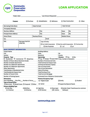
Application Notes:Comparison of the OZ ER meter with results from a polarimeterA common alternate technique used in polarization analysis is through the use of a polarimeter. These devices work by mathematicallymapping the output polarization from a source onto what is known as a Poincaré sphere. By monitoring the variation of the polarizationover time on this Poincaré sphere, one can calculate the variation in the polarization and presumably the degree of polarization itself.There are two principle drawbacks with this technique. The first is that to map the polarization onto the Poincaré sphere, polarimeterssubtract any randomly polarized light from the signal. Thus any calculation of the polarization extinction ratio using a polarimeter ignoresthis signal. This results in reported values that are more optimistic than that given by the OZ Extinction Ratio Meter. The Extinction RatioMeter gives a more conservative and more reliable result.The second drawback is that most fiber optic polarimeters utilize singlemode fiber to transmit light to its internal sensors. The singlemodefiber itself changes the polarization to an arbitrary polarization. Therefore fiber optic polarimeters are only suitable for measuring relativechanges. This makes them unsuitable for alignment of polarization maintaining connectors.General ConsiderationsOZ Optics Polarization Extinction Ratio Meters, together with OZ Optics Highly Stable Polarized Sources, provide a quick, reliable, andeffective means to align, characterize, and QA polarization maintaining components. To ensure that your measurements are as accurateas possible, the following precautions should be taken.1. Check your reference angle:The OZ Optics Extinction Ratio Meter provides a reading of the polarization axis orientation compared to the keyway on the receptacle.However, if the receptacle is exchanged or replaced, the orientation might be changed by a few degrees.To ensure that the angle reading is accurate, OZ Optics supplies master reference patchcords. These patchcords maintain polarizationto better than 30dB, and are aligned to within 1.5 degrees of the connector keyway. A menu option allows one to adjust the anglereference to any desired value, allowing one to compensate for any offset. Note that a misalignment of q degrees between the sourceand the fiber will degrade the extinction ratio and the maximum ER that can be achieved will be given by:ER 10 log (tan 2 q)2. Stress the fiber:When working with a highly coherent source, such as a DFB laser, it is possible to get readings that initially meet specifications, butdegrade over time. This degradation of the extinction level can take several minutes to occur. This behavior occurs because part of thelight within the fiber is traveling along the wrong axis. At the output end of the fiber the light traveling along the slow and fast axescombine to form a unique polarization state. If the two signals are in phase with one another, they will form linearly polarized light.However, as the fiber is stressed, the phase relation will change and so will the output polarization.To check for this behavior, one should stress the fiber while measuring the polarization. The meter has a data logging mode for thisfunction. To use it, activate the logging mode through the menu, then apply stress to the device under test. One common method is tosimply wrap the fiber several turns around a mandrel, 40 or 50 mm in diameter. Such a mandrel is available from OZ Optics. A secondtechnique is to heat the fiber with a warming plate. After stressing the fiber, stop the logging mode. The meter will then display the worstcase extinction ratio, and the variation in the polarization angle. Use these readings as the performance specification. Refer to themanual for further details.3. Look both ways:If a device is being used to transmit light in either direction, then it should be inspected in both directions. The performance of a devicewill depend on the direction in which it is used. This is because stresses and microbends usually occur near the fiber ends. If themicrobend is at the output end of the fiber, then the output polarization may be rotated, but otherwise remain static. However if themicrobend is at the input end, then the polarization is perturbed before travelling through the fiber, so the polarization will vary.4. Autoalign components using the computer interface.The meter can report both power and extinction ratios to a computer control system via the USB interface. This can be used to developan auto-alignment system. The power level can be reported at over 650 samples per second, which is sufficient for rapid alignment.A complete set of application notes, one on polarization measurements (POLARIZATION MAINTAINING MEASUREMENT SYSTEMS),the other on how to use the meter for alignment applications (AUTOMATED POLARIZATION ALIGNMENT) are available from ourwebsite (www.ozoptics.com).5. Measurement limitsThe detection circuitry for the ER meter has an overall dynamic range of about 60 dB. When the input signal has a power level withinthe range of 50 µW to 1 mW (a 13 dB range), this leaves at least a 47 dB range for the ER measurement itself. Since the extinction ratiois based on the ratio of two values, a minimum and a maximum, the minimum value may approach the noise floor of the instrument ifthe extinction ratio is really good or the input power is close to 50 µW or below. In such a case, the minimum value may default to thenoise floor of the instrument. Under these conditions, the instrument may not be able to provide an accurate reading. However, it will beable to determine a worst case value, which will be indicated to the user as such. By using a higher-powered source, the instrument willbe able to provide an improved reading. For example, with a low power signal, the ER meter may indicate that an extinction ratio is 27 dB. If the user needs to know whether the actual value is over 30 dB, then a more powerful source should be used. If the ER meterhas an optional attenuator installed, the user could simply remove the attenuator.5
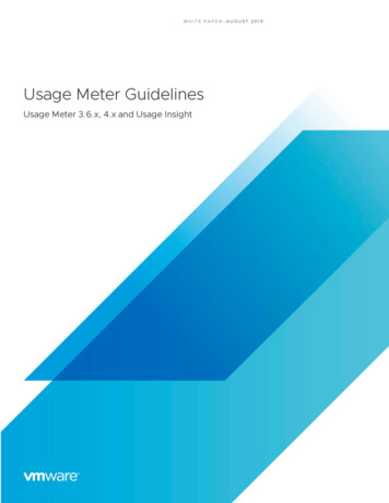
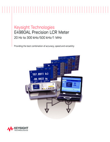
PM V-Groove Array ER MeasurementsOZ Optics ER Meter for PM V-Groove array's provides for fast andaccurate extinction ratio measurements of V-Groove assembliesmanufactured with PM fiber. The semi-automated system iscomputer controlled for hassle free control and measurements.The system consists of a polarized stable light source, 3 axismeasurement micro-stage with one axis motorized, an extinctionratio display set and PC software to control the system. The stageand meter display are connected to a PC using USB cables. Thesystem is capable of measuring extinction ratios up to 40dB withan angle accuracy of 1.5 . The ordering information is as follows:Bar Code13620Part NumberPER-KIT-3VGA-1550-1-ER 40Extinction Ratio Meter with Polarized Source (PFOSS)DescriptionPolarization Extinction Ratio Measurement System for testing V-Groove Arrays using 1550 nmpolarization maintaining patchcords terminated with FC connectors with Super PC or Ultra PCFinishes. Kit Contains the following:Source:PFOSS-02-3-1550-1-ER 40Meter:ER-11-1290/1650-ER 40 (Includes PC interface and software)Mount:ER-VGA-1290/1650-ER 40 (Includes positioning Stage)Patchcord: -0-ER 30-GOperating the PM V-Groove Array ER Measurement systemThe system works by first setting the software configurations for the appropriate V-Groove size and spacing. The V-Groove chip is thenattached to the mounting stage and the opposite end of the fiber is attached to the polarized source. After adjusting the stage to roughlyalign the fiber to the meter, the software is started to take the ER measurement and automatically move the array to the next fiberposition. Manual recording of the measured ER and angle is required at this point, optional software is available to log the measurementsfor later use. At the software prompt, the user must change the fiber on the polarized stable source so the next measurement can be taken.PM V-Groove Array Extinction Ratio Measurement System6
In addition the meter can provide a relative power readout, proportional to the input power in dB. This readout is updated at up to 650 times per second. The computer interface allows the unit to be used with . Fiber Optic Polarization Extinction Ratio Meter for wavelengths from 1290 nm to 1650 nm. ER 40 dB, without receptacle