Transcription
Reference Manual00809-1100-4004, Rev ACOctober 2021Rosemount 8800D Vortex Flow MeterFor Meters with Pressure Compensation (MPA) orPressure Temperature Compensation (MCA)
2
Reference Manual00809-1100-4004ContentsOctober 2021Contents Rosemount 8800D Vortex Flowmeter. 0Chapter 1Safety messages.7Chapter 2Introduction. 92.1 Overview. 9Chapter 3Pre-installation. 113.1 Planning. 113.2 Commissioning.17Chapter 4Basic installation. 214.1 Handling.214.2 Flow direction. 214.3 Gaskets.214.4 Insulation.224.5 Flanged-style flow meter mounting. 224.6 Wafer-style flow meter alignment and mounting. 244.7 Cable glands. 264.8 Flow meter grounding. 264.9 Grounding the transmitter case. 274.10 Conduit installation. 284.11 Wiring.284.12 Remote installation. 29Chapter 5Basic configuration. 375.1 About basic configuration.375.2 Process variables.375.3 Tag. 395.4 Long Tag.395.5 Process configuration. 395.6 Reference K-factor. 405.7 Flange type. 415.8 Pipe I.D. 415.9 Upper and lower range values. 425.10 Damping. 425.11 Optimize Digital Signal Processing (DSP). 43Chapter 6Advanced installation.456.1 Insert integral temperature sensor.456.2 Pulse output. 466.3 Transient protection. 47Rosemount 8800D Vortex Flow Meter with MPA or MCA option3
ContentsOctober 2021Reference Manual00809-1100-40046.4 Wire a HART pressure transmitter for pressure compensation. 50Chapter 7Advanced configuration. 537.1 LCD display. 537.2 Compensated K-factor.537.3 Meter body. 547.4 Meter factor.547.5 Variable mapping. 547.6 Alarm/saturation levels.557.7 Pulse output. 567.8 Mass compensation. 577.9 Configure HART pressure transmitter. 627.10 SMART fluid diagnostic. 627.11 HART multidrop communication. 647.12 Burst mode. 657.13 Optimizing HART systems for pressure compensation. 667.14 Signal processing.667.15 Device information. 687.16 Change HART revisions. 697.17 Special process variable units.697.18 Elapsed Time Meter. 707.19 Flow totalizer. 707.20 Locate device.71Chapter 8Troubleshooting. 738.1 Communication problem with HART-based communicator.738.2 Incorrect 4–20 mA output. 738.3 Incorrect pulse output. 748.4 Error messages on a HART-based communicator. 748.5 Flow in Pipe, No Output. 748.6 No flow, output. 758.7 Diagnostic messages. 768.8 Temperature and pressure compensation troubleshooting. 818.9 Electronics test points.82Chapter 9Maintenance. 859.1 Transient protection. 859.2 Installing the LCD indicator. 869.3 Hardware replacement. 889.4 Return of material.102Appendix AProduct Specifications.105A.1 Physical specifications. 105A.2 Performance specifications.1094Rosemount 8800D Vortex Flow Meter with MPA or MCA option
Reference Manual00809-1100-4004ContentsOctober 2021A.3 Typical flow rates.114A.4 HART specifications. 122A.5 LCD indicator functional specifications. 126Appendix BAppendix CSpacers. 127Electronics verification. 129C.1 Electronics verification using flow simulation mode.129C.2 Fixed flow rate simulation.130C.3 Varying flow rate simulation. 130C.4 Verify electronics using an external frequency generator.130C.5 Output variable calculations with known input frequency.132C.6 Unit conversion table.133C.7 Example calculations. 133Appendix DDual and Single Analog Wiring Configuration with the HART CommunicationBridge. 139Rosemount 8800D Vortex Flow Meter with MPA or MCA option5
ContentsOctober 20216Reference Manual00809-1100-4004Rosemount 8800D Vortex Flow Meter with MPA or MCA option
Reference Manual00809-1100-40041Safety messagesOctober 2021Safety messagesWARNINGExplosion hazards. Failure to follow these instructions could cause an explosion,resulting in death or serious injury. Verify the operating atmosphere of the transmitter is consistent with theappropriate hazardous locations certifications. Installation of this transmitter in an explosive environment must be in accordancewith the appropriate local, national, and international standards, codes, andpractices. Review the approvals documents for any restrictions associated with a safeinstallation. Do not remove transmitter covers or thermocouple (if equipped) in explosiveatmospheres when the circuit is live. Both transmitter covers must be fully engagedto meet explosion-proof requirements. Before connecting a hand-held communicator in an explosive atmosphere, makesure the instruments in the loop are installed in accordance with intrinsically safe ornon-incendive field wiring practices.WARNINGElectrical shock hazard. Failure to follow this instruction could result in death or seriousinjury. Avoid contact with the leads and terminals. High voltage that may be present onleads can cause electrical shock.WARNINGGeneral hazard. Failure to follow these instructions could result in death or seriousinjury. This product is intended to be used as a flowmeter for liquid, gas, or steamapplications. Do not use for any other purpose. Make sure only qualified personnel perform the installation.Rosemount 8800D Vortex Flow Meter with MPA or MCA option7
Safety messagesOctober 20218Reference Manual00809-1100-4004Rosemount 8800D Vortex Flow Meter with MPA or MCA option
Reference Manual00809-1100-4004IntroductionOctober 20212Introduction2.1OverviewSystem descriptionThe Vortex Flow Meter consists of a meter body and transmitter, and measures volumetricflow rate by detecting the vortices created by a fluid passing by the shedder bar.The meter body is installed in-line with process piping. A sensor is located at the end of theshedder bar which creates a sine wave signal due to the passing vortices. The transmittermeasures the frequency of the sine wave and converts it into a flow rate.Safety messagesProcedures and instructions in this manual may require special precautions to ensure thesafety of the personnel performing the operations. Refer to the safety messages listed atthe beginning of this document, before performing any operations.ChaptersSectionWho usesDescriptionPre-installationPlanners andinstallersReference information to help you verify compatibilitybetween the meter and its application and installationlocationBasic installationPlanners andinstallersMechanical and electrical installation instructions typicallyrequired as initial setup in all sConfiguration parameters typically required as initial setupin all tion procedures required after initial setup forsome iansConfiguration procedures required after initial setup forsome ion on advanced configuration parameters andfunctions that can aid in maintaining the flow meterTroubleshootingInstallers andoperationstechniciansTroubleshooting techniques, diagnostic information, andtransmitter verification ion on maintaining the flow meterAppendixesAppendixes include supplementary information that may be useful in some situations.Rosemount 8800D Vortex Flow Meter with MPA or MCA option9
IntroductionOctober 202110Reference Manual00809-1100-4004Rosemount 8800D Vortex Flow Meter with MPA or MCA option
Reference Manual00809-1100-4004Pre-installationOctober 20213Pre-installation3.1Planning3.1.1SizingTo determine the correct meter size for optimal flow meter performance: Determine the limits of measuring flow. Determine the process conditions so that they are within the stated requirements forReynolds number and velocity.For sizing details, see Product Specifications.Sizing calculations are required to select the proper flow meter size. These calculationsprovide pressure loss, accuracy, and minimum and maximum flow rate data to guide inproper selection. Vortex sizing software can be found using the Selection and Sizing tool.The Selection and Sizing tool can be accessed online or downloaded for offline use usingthis link: www.Emerson.com/FlowSizing.3.1.2Wetted material selectionEnsure that the process fluid is compatible with the meter body wetted materials whenspecifying the Rosemount 8800D. Corrosion will shorten the life of the meter body.Consult recognized sources of corrosion data or contact technical support for moreinformation.NoteIf Positive Material Identification (PMI) is required, perform test on a machined surface.3.1.3OrientationThe best orientation for the meter depends on the process fluid, environmental factors,and any other nearby equipment.Vertical installationVertical, upward, installation allows upward process liquid flow and is generally preferred.Upward flow ensures that the meter body always remains full and that any solids in thefluid are evenly distributed.The meter can be mounted in the vertical down position when measuring gas or steamflows. This type of application is strongly discouraged for liquid flows, although it can bedone with proper piping design.Rosemount 8800D Vortex Flow Meter with MPA or MCA option11
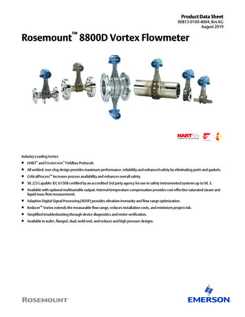
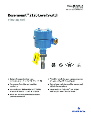
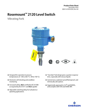
Pre-installationOctober 2021Reference Manual00809-1100-4004Figure 3-1: Vertical installationABA. Liquid or gas flowB. Gas flowNoteTo ensure the meter body remains full, avoid downward vertical liquid flows where backpressure is inadequate.Horizontal installationFor horizontal installation, the preferred orientation is to have the electronics installed tothe side of the pipe. In liquid applications, this helps prevent any entrained air or solidsfrom striking the shedder bar and disrupting the shedding frequency. In gas or steamapplications, this helps prevent any entrained liquid (such as condensate) or solids fromstriking the shedder bar and disrupting the shedding frequency.Figure 3-2: Horizontal installationBAA. Preferred installation—meter body installed with electronics to side of pipeB. Acceptable installation—meter body installed with electronics above pipeHigh-temperature installationsThe maximum process temperature for integral electronics is dependent on the ambienttemperature where the meter is installed. The electronics must not exceed 185 F (85 C).Figure 3-3 shows combinations of ambient and process temperatures needed to maintaina housing temperature of less than 185 F (85 C).12Rosemount 8800D Vortex Flow Meter with MPA or MCA option
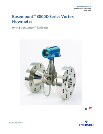
Reference Manual00809-1100-4004Pre-installationOctober 2021Figure 3-3: Ambient/Process temperature limits200 (93)180(82)160 (71)AC140 (60)120 (49)100 (38)900 (482)700 (371)800 (427)500 (260)600 (316)400 (204)200 (93)300 (149)0100 (38)60 (16)1000 (538)80 (27)BA. Ambient temperature F ( C)B. Process temperature F ( C)C. 185 F (85 C) Housing temperature limit.NoteThe indicated limits are for horizontal pipe and vertical meter position, with meter andpipe insulated with 3 in. (77 mm) of ceramic fiber insulation.Install the meter body so the electronics are positioned to the side of the pipe or below thepipe as shown in Figure 3-4. Insulation may also be required around the pipe to maintainan electronics temperature below 185 F (85 C). See Figure 4-2 for special insulationconsiderations.Figure 3-4: Examples of high-temperature installationsBAA. Preferred installation—The meter body installed with the electronics to the side of thepipe.B. Acceptable installation—The meter body installed with the electronics below the pipe.3.1.4LocationHazardous areaThe transmitter has an explosion-proof housing and circuitry suitable for intrinsically safeand non-incendive operation. Individual transmitters are clearly marked with a tagRosemount 8800D Vortex Flow Meter with MPA or MCA option13
Pre-installationOctober 2021Reference Manual00809-1100-4004indicating the certifications they carry. For hazardous location installation, includingExplosion-proof, Flameproof,or Intrinsic Safety (I.S.), please consult the Emerson 8800Approval Document 00825-VA00-0001.Environmental considerationsAvoid excessive heat and vibration to ensure maximum flow meter life. Typical problemareas include high-vibration lines with integrally mounted electronics, warm-climateinstallations in direct sunlight, and outdoor installations in cold climates.Although the signal conditioning functions reduce susceptibility to extraneous noise,some environments are more suitable than others. Avoid placing the flow meter or itswiring close to devices that produce high intensity electromagnetic and electrostaticfields. Such devices include electric welding equipment, large electric motors andtransformers, and communication transmitters.Upstream and downstream pipingThe meter may be installed with a minimum of ten diameters (D) of straight pipe lengthupstream and five diameters (D) of straight pipe length downstream.To achieve reference accuracy, straight pipe lengths of 35D upstream and 5D downstreamare required. The value of the K-factor may shift up to 0.5% when the upstream straightpipe length is between 10D and 35D. For optional K-factor corrections, see Rosemount 8800 Vortex Installation Effects Technical Data Sheet. To correct this effect, see Meter factor.Steam pipingFor steam applications, avoid installations such as the one shown in the following figure.Such installations may cause a water-hammer condition at start-up due to trappedcondensation. The high force from the water hammer can stress the sensing mechanismand cause permanent damage to the sensor.Figure 3-5: Wrong steam pipe installationPressure and temperature transmitter locationWhen using pressure and temperature transmitters in conjunction with the vortex flowmeter for compensated mass flows, install the transmitter(s) downstream of the vortexflow meter.14Rosemount 8800D Vortex Flow Meter with MPA or MCA option
Reference Manual00809-1100-4004Pre-installationOctober 2021Figure 3-6: Pressure and temperature transmitter locationABA.B.C.D.3.1.5CDPressure transmitterFour straight pipe diameters downstreamTemperature transmitterSix straight pipe diameters downstreamPower supplyAnalog 4–20 mA Power supplyExternal power supply required. Each transmitter operates on 10.8 VDC to 42 VDCterminal voltage.Power consumptionOne watt maximum per transmitter.Rosemount 8800D Vortex Flow Meter with MPA or MCA option15
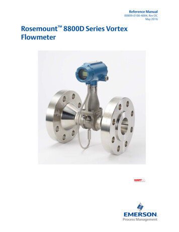
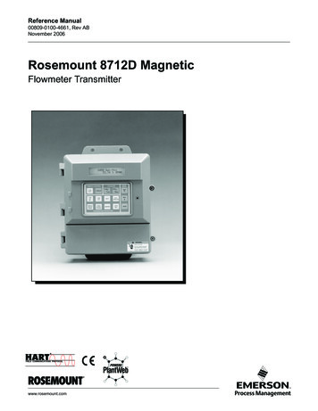
Pre-installationOctober 2021Reference Manual00809-1100-4004HART communicationFigure 3-7: HART communication voltage/resistance requirement 5 വ 9SVMaximum loop resistance is determined by the voltage level of the external power supply,as described in the graph.Note that HART Communication requires a minimum loop resistance of 250 ohms up to amaximum of 1100 ohms.R(Ω)Load resistor value.VpsMinimum power supply voltage requiredR(Ω)max 41.7 (Vps – 10.8 V).Additional wiring information The DC power supply should provide power with less than two percent ripple. The totalresistance load is the sum of the resistance of the signal wiring and the load resistanceof the controller, indicator, and related pieces. Note that the resistance of intrinsicsafety barriers, if used, must be included. If a Smart Wireless THUM Adapter is being used with the flow meter to exchangeinformation via IEC 62591 (WirelessHART Protocol) technology, a minimum loopresistance of 250 ohms is required. In addition, a minimum power supply voltage (Vps)of 19.3 volts will be required to output 24 mA. If a single power supply is used to power more than one transmitter, the power supplyused and circuitry common to the transmitters should not have more than 20 ohms ofimpedance at 1200 Hz. See Table 3-1. Loop resistance must be considered in determining the minimum power supplyvoltage.16Rosemount 8800D Vortex Flow Meter with MPA or MCA option
Reference Manual00809-1100-4004Pre-installationOctober 2021Table 3-1: Resistance based on wire gauge3.2Gauge numberOhms per 1,000 ft (305 m) at 68 F (20 C)equivalent14 AWG (2 mm2)2.516 AWG (1 mm2)4.018 AWG (0.8mm2)6.420 AWG (0.5 mm2)1022 AWG (0.3 mm2)1624 AWG (0.2 mm2)26CommissioningFor proper configuration and operation, commission the meter before putting it intooperation. Bench commissioning also enables you to check hardware settings, test theflowmeter electronics, verify flowmeter configuration data, and check output variables.Any problems can be corrected—or configuration settings changed—before going out intothe installation environment. To commission on the bench, connect a configurationdevice to the signal loop in accordance the device instructions.3.2.1Alarm and security jumper configurationTwo jumpers on the transmitter specify the alarm and security modes. Set these jumpersduring the commissioning stage to avoid exposing the electronics to the plantenvironment. The two jumpers can be found on the electronics board stack or on the LCDdisplay.AlarmAs part of normal operations, the transmitter continuously runs a selfdiagnostic routine. If the routine detects an internal failure in the electronics,flow meter output is driven to a low or high alarm level, depending on theposition of the failure mode jumper. The factory sets the jumper according tothe Configuration Data Sheet, if applicable, or HI by default.Security You can protect the configuration data with the security lockout jumper. Withthe security lockout jumper ON, any configuration changes attempted on theelectronics are disallowed. You can still access and review any of the operatingparameters and scroll through the available parameters, but no changes canbe made. The factory sets the jumper according to the Configuration DataSheet, if applicable, or OFF by default.NoteIf you will be changing configuration variables frequently, it may be useful toleave the security lockout jumper in the OFF position to avoid exposing theflow meter electronics to the plant environment.To access the jumpers, remove the transmitter electronics housing or the LCD cover (ifequipped) opposite of the terminal block, See Figure 3-8 and Figure 3-9.Rosemount 8800D Vortex Flow Meter with MPA or MCA option17
Pre-installationOctober 2021Reference Manual00809-1100-4004Figure 3-8: Alarm and security jumpers (no LCD option)VORTEX4-20mAHARTTEST FREQINTP1Figure 3-9: Alarm and security jumpers (with LCD option)HILOALARMFLOWSECURITYONOFFFailure mode vs. saturation output valuesThe failure mode alarm output levels differ from the output values that occur when theoperating flow is outside the range points. When the operating flow is outside the rangepoints, the analog output continues to track the operating flow until reaching thesaturation value listed below; the output does not exceed the listed saturation valueregardless of the operating flow. For example, with standard alarm and saturation levelsand flows outside the 4–20 mA range points, the output saturates at 3.9 mA or 20.8 mA.When the transmitter diagnostics detect a failure, the analog output is set to a specificalarm value that differs from the saturation value to allow for proper troubleshooting. Thesaturation and alarm levels are software selectable between Rosemount Standard andNAMUR levels.18Rosemount 8800D Vortex Flow Meter with MPA or MCA option
Reference Manual00809-1100-4004Pre-installationOctober 2021Table 3-2: Analog output: standard alarm values vs. saturation valuesLevel4–20 mA saturation value4–20 mA alarm valueLow3.9 mA 3.75 mAHigh20.8 mA 21.75 mATable 3-3: Analog output: NAMUR-compliant alarm values vs. saturation values3.2.2Level4–20 mA saturation value4–20 mA alarm valueLow3.8 mA 3.6 mAHigh20.5 mA 22.6 mACalibrationThe flow meter is wet-calibrated at the factory and needs no further calibration duringinstallation. The calibration factor (K-factor) is indicated on each meter body and isentered into the electronics. Verification can be accomplished with a configuration device.Rosemount 8800D Vortex Flow Meter with MPA or MCA option19
Pre-installationOctober 202120Reference Manual00809-1100-4004Rosemount 8800D Vortex Flow Meter with MPA or MCA option
Reference Manual00809-1100-4004Basic installationOctober 20214Basic installation4.1HandlingHandle all parts carefully to prevent damage. Whenever possible, transport the system tothe installation site in the original shipping containers. Keep the shipping plugs in theconduit connections until you are ready to connect and seal them.NOTICETo avoid damage to the meter, do not lift the flow meter by the transmitter. Lift the meterby the meter body. Lifting supports can be tied around the meter body as shown.Figure 4-1: Lifting supports4.2Flow directionThe meter can only measure flow in the direction indicated on the meter body. Be sure tomount the meter body so the FORWARD end of the flow arrow points in
Reference Manual 00809-1100-4004, Rev AC October 2021 Rosemount 8800D Vortex Flow Meter For Meters with Pressure Compensation (MPA) or Pressure Temperature Compensation (MCA)