Transcription
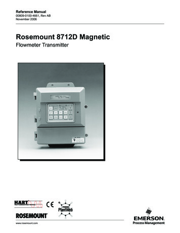
Reference Manual00809-0100-4661, Rev ABNovember 2006Rosemount 8712D MagneticFlowmeter Transmitterwww.rosemount.com
Reference Manual00809-0100-4661, Rev ABNovember 2006Rosemount 8712DRosemount 8712D MagneticFlowmeter TransmitterNOTICERead this manual before working with the product. For personal and system safety, andfor optimum product performance, make sure you thoroughly understand the contentsbefore installing, using, or maintaining this product.Within the United States, Rosemount Inc. has two toll-free assistance numbers:Customer CentralTechnical support, quoting, and order-related questions.1-800-999-9307 (7:00 am to 7:00 pm CST)North American Response CenterEquipment service needs.1-800-654-7768 (24 hours—includes Canada)Outside of the United States, contact your local Rosemount representative.The products described in this document are NOT designed for nuclear-qualifiedapplications. Using non-nuclear qualified products in applications that requirenuclear-qualified hardware or products may cause inaccurate readings.For information on Rosemount nuclear-qualified products, contact your local RosemountSales Representative.www.rosemount.com
Reference Manual00809-0100-4661, Rev ABNovember 2006Rosemount 8712DTable of ContentsSECTION 1IntroductionSystem Description . . . . . . . . . . . . . . . . . . . . . . . . . . . . . . . . . . . . . . . 1-1Safety Messages . . . . . . . . . . . . . . . . . . . . . . . . . . . . . . . . . . . . . . . . . 1-2Service Support . . . . . . . . . . . . . . . . . . . . . . . . . . . . . . . . . . . . . . . . . . 1-2SECTION 2InstallationSafety Messages . . . . . . . . . . . . . . . . . . . . . . . . . . . . . . . . . . . . . . . . . 2-1Transmitter Symbols . . . . . . . . . . . . . . . . . . . . . . . . . . . . . . . . . . . . . . 2-2Pre-Installation. . . . . . . . . . . . . . . . . . . . . . . . . . . . . . . . . . . . . . . . . . . 2-2Mechanical Considerations . . . . . . . . . . . . . . . . . . . . . . . . . . . . . . 2-2Environmental Considerations . . . . . . . . . . . . . . . . . . . . . . . . . . . . 2-3Installation Procedures . . . . . . . . . . . . . . . . . . . . . . . . . . . . . . . . . . . . 2-3Mount the Transmitter . . . . . . . . . . . . . . . . . . . . . . . . . . . . . . . . . . 2-3Pipe Mounting . . . . . . . . . . . . . . . . . . . . . . . . . . . . . . . . . . . . . . 2-3Surface Mounting . . . . . . . . . . . . . . . . . . . . . . . . . . . . . . . . . . . 2-3Identify Options and Configurations . . . . . . . . . . . . . . . . . . . . . . . . 2-4Hardware Switches. . . . . . . . . . . . . . . . . . . . . . . . . . . . . . . . . . . . . 2-4Changing Hardware Switch Settings. . . . . . . . . . . . . . . . . . . . . 2-4Failure Alarm Mode . . . . . . . . . . . . . . . . . . . . . . . . . . . . . . . . . . 2-4Internal/External Analog Power. . . . . . . . . . . . . . . . . . . . . . . . . 2-4Transmitter Security . . . . . . . . . . . . . . . . . . . . . . . . . . . . . . . . . 2-4Changing Hardware Switch Settings. . . . . . . . . . . . . . . . . . . . . 2-5Conduit Ports and Connections . . . . . . . . . . . . . . . . . . . . . . . . . . . 2-5Conduit Cables . . . . . . . . . . . . . . . . . . . . . . . . . . . . . . . . . . . . . . . . 2-6Electrical Considerations . . . . . . . . . . . . . . . . . . . . . . . . . . . . . . . . 2-6Transmitter Input Power . . . . . . . . . . . . . . . . . . . . . . . . . . . . . . 2-6Requirements for 90-250 V ac Power Supply . . . . . . . . . . . . . . 2-6Requirements for 12-42 V dc Power Supply . . . . . . . . . . . . . . . 2-6Installation Category. . . . . . . . . . . . . . . . . . . . . . . . . . . . . . . . . . . . 2-8Overcurrent Protection . . . . . . . . . . . . . . . . . . . . . . . . . . . . . . . . . . 2-8Options, Considerations, and Procedures . . . . . . . . . . . . . . . . . . . . . . 2-8Connect Transmitter Power . . . . . . . . . . . . . . . . . . . . . . . . . . . . . . 2-8Connect 4–20 mA Loop External Power Source . . . . . . . . . . . . . . 2-9Connect Pulse Output Power Source. . . . . . . . . . . . . . . . . . . . . . 2-10Connect Digital Output 1 . . . . . . . . . . . . . . . . . . . . . . . . . . . . . . . 2-11Connect Digital Input 2 . . . . . . . . . . . . . . . . . . . . . . . . . . . . . . . . . 2-12Flowtube Connections . . . . . . . . . . . . . . . . . . . . . . . . . . . . . . . . . . . . 2-12Rosemount Flowtubes . . . . . . . . . . . . . . . . . . . . . . . . . . . . . . . . . 2-12Transmitter toFlowtube Wiring . . . . . . . . . . . . . . . . . . . . . . . . . . . . . . . . . . . . . . 2-12Conduit Cables . . . . . . . . . . . . . . . . . . . . . . . . . . . . . . . . . . . . . . . 2-14Flowtube to Remote Mount Transmitter Connections . . . . . . . . . 2-15www.rosemount.com
Reference Manual00809-0100-4661, Rev ABNovember 2006SECTION 3ConfigurationRosemount 8712DIntroduction . . . . . . . . . . . . . . . . . . . . . . . . . . . . . . . . . . . . . . . . . . . . . 3-1Installation Check and Guide. . . . . . . . . . . . . . . . . . . . . . . . . . . . . . . . 3-2Before You Begin . . . . . . . . . . . . . . . . . . . . . . . . . . . . . . . . . . . 3-2Transmitter . . . . . . . . . . . . . . . . . . . . . . . . . . . . . . . . . . . . . . . . 3-2Flowtube . . . . . . . . . . . . . . . . . . . . . . . . . . . . . . . . . . . . . . . . . . 3-2Wiring . . . . . . . . . . . . . . . . . . . . . . . . . . . . . . . . . . . . . . . . . . . . 3-2Process Fluid. . . . . . . . . . . . . . . . . . . . . . . . . . . . . . . . . . . . . . . 3-2Local Operator Interface . . . . . . . . . . . . . . . . . . . . . . . . . . . . . . . . . . . 3-3Basic Features. . . . . . . . . . . . . . . . . . . . . . . . . . . . . . . . . . . . . . . . . . . 3-3Display Control Keys . . . . . . . . . . . . . . . . . . . . . . . . . . . . . . . . . 3-3Totalizer Keys . . . . . . . . . . . . . . . . . . . . . . . . . . . . . . . . . . . . . . 3-3Data Entry Keys . . . . . . . . . . . . . . . . . . . . . . . . . . . . . . . . . . . . 3-3Transmitter Parameter Keys . . . . . . . . . . . . . . . . . . . . . . . . . . . 3-3Data Entry. . . . . . . . . . . . . . . . . . . . . . . . . . . . . . . . . . . . . . . . . . . . 3-3Selecting Options . . . . . . . . . . . . . . . . . . . . . . . . . . . . . . . . . . . . . . 3-4LOI Examples . . . . . . . . . . . . . . . . . . . . . . . . . . . . . . . . . . . . . . . . . . . 3-4Table Value Example . . . . . . . . . . . . . . . . . . . . . . . . . . . . . . . . . . . 3-4Select Value Example . . . . . . . . . . . . . . . . . . . . . . . . . . . . . . . . . . 3-4Diagnostic Messages. . . . . . . . . . . . . . . . . . . . . . . . . . . . . . . . . . . . . . 3-6Process Variables . . . . . . . . . . . . . . . . . . . . . . . . . . . . . . . . . . . . . . . . 3-6Basic Setup . . . . . . . . . . . . . . . . . . . . . . . . . . . . . . . . . . . . . . . . . . . . . 3-6Tag . . . . . . . . . . . . . . . . . . . . . . . . . . . . . . . . . . . . . . . . . . . . . . . . . 3-6Flow Rate Units . . . . . . . . . . . . . . . . . . . . . . . . . . . . . . . . . . . . . . . 3-7URV (Upper Range Value) . . . . . . . . . . . . . . . . . . . . . . . . . . . . . . . 3-7LRV (Lower Range Value) . . . . . . . . . . . . . . . . . . . . . . . . . . . . . . . 3-8Example . . . . . . . . . . . . . . . . . . . . . . . . . . . . . . . . . . . . . . . . . . 3-8Line Size. . . . . . . . . . . . . . . . . . . . . . . . . . . . . . . . . . . . . . . . . . . . . 3-8Calibration Number. . . . . . . . . . . . . . . . . . . . . . . . . . . . . . . . . . . . . 3-9Damping . . . . . . . . . . . . . . . . . . . . . . . . . . . . . . . . . . . . . . . . . . . . . 3-9Detailed Setup . . . . . . . . . . . . . . . . . . . . . . . . . . . . . . . . . . . . . . . . . . . 3-9Pulse Output Scaling . . . . . . . . . . . . . . . . . . . . . . . . . . . . . . . . . . . 3-9Pulse Width . . . . . . . . . . . . . . . . . . . . . . . . . . . . . . . . . . . . . . . . . 3-10Special Units. . . . . . . . . . . . . . . . . . . . . . . . . . . . . . . . . . . . . . . . . 3-12User-Defined Volume Unit . . . . . . . . . . . . . . . . . . . . . . . . . . . . . . 3-12Base Volume Unit. . . . . . . . . . . . . . . . . . . . . . . . . . . . . . . . . . . . . 3-12Conversion Number . . . . . . . . . . . . . . . . . . . . . . . . . . . . . . . . . . . 3-12Base Time Unit . . . . . . . . . . . . . . . . . . . . . . . . . . . . . . . . . . . . . . . 3-12User-Defined Flow Unit . . . . . . . . . . . . . . . . . . . . . . . . . . . . . . . . 3-13Auxiliary Output . . . . . . . . . . . . . . . . . . . . . . . . . . . . . . . . . . . . . . 3-13Reverse Flow . . . . . . . . . . . . . . . . . . . . . . . . . . . . . . . . . . . . . 3-13Zero Flow . . . . . . . . . . . . . . . . . . . . . . . . . . . . . . . . . . . . . . . . 3-13Reverse Flow Enable . . . . . . . . . . . . . . . . . . . . . . . . . . . . . . . . . 3-13Empty Pipe . . . . . . . . . . . . . . . . . . . . . . . . . . . . . . . . . . . . . . . . . 3-13Empty Pipe Value . . . . . . . . . . . . . . . . . . . . . . . . . . . . . . . . . . . . . 3-13Empty Pipe Trigger Level . . . . . . . . . . . . . . . . . . . . . . . . . . . . . . . 3-14Empty Pipe Counts . . . . . . . . . . . . . . . . . . . . . . . . . . . . . . . . . . 3-14Totalizer . . . . . . . . . . . . . . . . . . . . . . . . . . . . . . . . . . . . . . . . . . 3-14Measure Gross Total . . . . . . . . . . . . . . . . . . . . . . . . . . . . . . . . . . 3-14Start Totalizer . . . . . . . . . . . . . . . . . . . . . . . . . . . . . . . . . . . . . . . . 3-14Stop Totalizer . . . . . . . . . . . . . . . . . . . . . . . . . . . . . . . . . . . . . . . . 3-14Reset Totalizer . . . . . . . . . . . . . . . . . . . . . . . . . . . . . . . . . . . . . . . 3-14Alarm Level. . . . . . . . . . . . . . . . . . . . . . . . . . . . . . . . . . . . . . . . . . 3-15Low Flow Cutoff . . . . . . . . . . . . . . . . . . . . . . . . . . . . . . . . . . . . . . 3-15TOC-2
Reference Manual00809-0100-4661, Rev ABNovember 2006Rosemount 8712DCoil Drive Frequency . . . . . . . . . . . . . . . . . . . . . . . . . . . . . . . . . . 3-155 Hz . . . . . . . . . . . . . . . . . . . . . . . . . . . . . . . . . . . . . . . . . . . . . 3-1537 Hz . . . . . . . . . . . . . . . . . . . . . . . . . . . . . . . . . . . . . . . . . . . . 3-15Control Status . . . . . . . . . . . . . . . . . . . . . . . . . . . . . . . . . . . . . . . 3-15Normal Mode (LOI Command Only) . . . . . . . . . . . . . . . . . . . . 3-15Filter Mode (LOI Command Only) . . . . . . . . . . . . . . . . . . . . . . 3-15Signal Processing Control . . . . . . . . . . . . . . . . . . . . . . . . . . . . . . 3-16On/Off . . . . . . . . . . . . . . . . . . . . . . . . . . . . . . . . . . . . . . . . . . . 3-16Number of Samples . . . . . . . . . . . . . . . . . . . . . . . . . . . . . . . . . . . 3-160 to 125 Samples . . . . . . . . . . . . . . . . . . . . . . . . . . . . . . . . . . 3-16Maximum Percent Limit . . . . . . . . . . . . . . . . . . . . . . . . . . . . . . . . 3-160 to 100 Percent . . . . . . . . . . . . . . . . . . . . . . . . . . . . . . . . . . . 3-16Time Limit . . . . . . . . . . . . . . . . . . . . . . . . . . . . . . . . . . . . . . . . . . . 3-160 to 256 Seconds . . . . . . . . . . . . . . . . . . . . . . . . . . . . . . . . . . 3-16Review Variables . . . . . . . . . . . . . . . . . . . . . . . . . . . . . . . . . . . . . . . . 3-17Review . . . . . . . . . . . . . . . . . . . . . . . . . . . . . . . . . . . . . . . . . . . . . 3-17Miscellaneous Functions . . . . . . . . . . . . . . . . . . . . . . . . . . . . . . . . . . 3-17Message . . . . . . . . . . . . . . . . . . . . . . . . . . . . . . . . . . . . . . . . . . . . 3-17Date . . . . . . . . . . . . . . . . . . . . . . . . . . . . . . . . . . . . . . . . . . . . . . . 3-17Flowtube Tag . . . . . . . . . . . . . . . . . . . . . . . . . . . . . . . . . . . . . . . . 3-17Flowtube Serial Number . . . . . . . . . . . . . . . . . . . . . . . . . . . . . . . . 3-17Transmitter Tag . . . . . . . . . . . . . . . . . . . . . . . . . . . . . . . . . . . . . . 3-17Liner Material . . . . . . . . . . . . . . . . . . . . . . . . . . . . . . . . . . . . . . . . 3-17Electrode Type . . . . . . . . . . . . . . . . . . . . . . . . . . . . . . . . . . . . . . . 3-18Electrode Material. . . . . . . . . . . . . . . . . . . . . . . . . . . . . . . . . . . . . 3-18Flange Material. . . . . . . . . . . . . . . . . . . . . . . . . . . . . . . . . . . . . . . 3-18Flange Type . . . . . . . . . . . . . . . . . . . . . . . . . . . . . . . . . . . . . . . . . 3-18D/A Trim and (4 20 mA Output Trim) . . . . . . . . . . . . . . . . . . . . . . 3-19Simulate Alarm . . . . . . . . . . . . . . . . . . . . . . . . . . . . . . . . . . . . . . 3-19Scaled D/A Trim . . . . . . . . . . . . . . . . . . . . . . . . . . . . . . . . . . . . . . 3-19Electronics Trim . . . . . . . . . . . . . . . . . . . . . . . . . . . . . . . . . . . . . . 3-20Auto Zero Trim . . . . . . . . . . . . . . . . . . . . . . . . . . . . . . . . . . . . . . . 3-21Universal Auto Trim . . . . . . . . . . . . . . . . . . . . . . . . . . . . . . . . . . . 3-21Multidrop Communications . . . . . . . . . . . . . . . . . . . . . . . . . . . . . . . . 3-22HandHeld Communicator . . . . . . . . . . . . . . . . . . . . . . . . . . . . . . . . . 3-22Connections and Hardware . . . . . . . . . . . . . . . . . . . . . . . . . . . . . . . . 3-25Basic Features. . . . . . . . . . . . . . . . . . . . . . . . . . . . . . . . . . . . . . . . . . 3-26Action Keys. . . . . . . . . . . . . . . . . . . . . . . . . . . . . . . . . . . . . . . . . . 3-26Alphanumeric and Shift Keys . . . . . . . . . . . . . . . . . . . . . . . . . . . . 3-27Data Entry . . . . . . . . . . . . . . . . . . . . . . . . . . . . . . . . . . . . . . . . 3-27Fast Key Feature . . . . . . . . . . . . . . . . . . . . . . . . . . . . . . . . . . . . . 3-28Fast Key Example . . . . . . . . . . . . . . . . . . . . . . . . . . . . . . . . . . 3-28Menus and Functions . . . . . . . . . . . . . . . . . . . . . . . . . . . . . . . . . . . . 3-28Main Menu . . . . . . . . . . . . . . . . . . . . . . . . . . . . . . . . . . . . . . . . . . 3-28Online Menu . . . . . . . . . . . . . . . . . . . . . . . . . . . . . . . . . . . . . . . . . 3-29Diagnostic Messages . . . . . . . . . . . . . . . . . . . . . . . . . . . . . . . . . . 3-30SECTION 4Flowtube InstallationSafety Messages . . . . . . . . . . . . . . . . . . . . . . . . . . . . . . . . . . . . . . . . . 4-1Flowtube Handling . . . . . . . . . . . . . . . . . . . . . . . . . . . . . . . . . . . . . . . . 4-3Flowtube Mounting . . . . . . . . . . . . . . . . . . . . . . . . . . . . . . . . . . . . . . . 4-4Upstream/DownstreamPiping . . . . . . . . . . . . . . . . . . . . . . . . . . . . . . . . . . . . . . . . . . . . . . . 4-4TOC-3
Reference Manual00809-0100-4661, Rev ABNovember 2006Rosemount 8712DFlowtube Orientation . . . . . . . . . . . . . . . . . . . . . . . . . . . . . . . . . . . 4-4Flow Direction. . . . . . . . . . . . . . . . . . . . . . . . . . . . . . . . . . . . . . . . . 4-6Installation (Flanged Flowtube) . . . . . . . . . . . . . . . . . . . . . . . . . . . . . . 4-7Gaskets . . . . . . . . . . . . . . . . . . . . . . . . . . . . . . . . . . . . . . . . . . . . . 4-7Flange Bolts . . . . . . . . . . . . . . . . . . . . . . . . . . . . . . . . . . . . . . . . . . 4-7Installation(Wafer Flowtube) . . . . . . . . . . . . . . . . . . . . . . . . . . . . . . . . . . . . . . . . 4-10Gaskets . . . . . . . . . . . . . . . . . . . . . . . . . . . . . . . . . . . . . . . . . . . . 4-10Flange Bolts . . . . . . . . . . . . . . . . . . . . . . . . . . . . . . . . . . . . . . . . . 4-11Installation(Sanitary Flowtube) . . . . . . . . . . . . . . . . . . . . . . . . . . . . . . . . . . . . . . 4-12Gaskets . . . . . . . . . . . . . . . . . . . . . . . . . . . . . . . . . . . . . . . . . . . . 4-12Alignment and Bolting. . . . . . . . . . . . . . . . . . . . . . . . . . . . . . . . . . 4-12Grounding . . . . . . . . . . . . . . . . . . . . . . . . . . . . . . . . . . . . . . . . . . . . . 4-12Process Leak Protection (Optional) . . . . . . . . . . . . . . . . . . . . . . . . . . 4-16Standard Housing Configuration . . . . . . . . . . . . . . . . . . . . . . . . . 4-16Relief Valves. . . . . . . . . . . . . . . . . . . . . . . . . . . . . . . . . . . . . . . . . 4-17Process Leak Containment . . . . . . . . . . . . . . . . . . . . . . . . . . . . . 4-17SECTION 5Maintenance andTroubleshootingSafety Information . . . . . . . . . . . . . . . . . . . . . . . . . . . . . . . . . . . . . . . . 5-1Diagnostic Messages. . . . . . . . . . . . . . . . . . . . . . . . . . . . . . . . . . . . . . 5-2Transmitter Troubleshooting . . . . . . . . . . . . . . . . . . . . . . . . . . . . . . . . 5-4Diagnostics and Service . . . . . . . . . . . . . . . . . . . . . . . . . . . . . . . . . . . 5-6Analog Output Test. . . . . . . . . . . . . . . . . . . . . . . . . . . . . . . . . . . . . 5-6Pulse Output Test. . . . . . . . . . . . . . . . . . . . . . . . . . . . . . . . . . . . . . 5-6Self Test . . . . . . . . . . . . . . . . . . . . . . . . . . . . . . . . . . . . . . . . . . . . . 5-6Quick Troubleshooting. . . . . . . . . . . . . . . . . . . . . . . . . . . . . . . . . . . . . 5-7Step 1: Wiring Errors . . . . . . . . . . . . . . . . . . . . . . . . . . . . . . . . . . . 5-7Step 2: Process Noise . . . . . . . . . . . . . . . . . . . . . . . . . . . . . . . . . . 5-7Step 3: Installed Flowtube Tests . . . . . . . . . . . . . . . . . . . . . . . . . . 5-7Step 4: Uninstalled Flowtube Tests . . . . . . . . . . . . . . . . . . . . . . . . 5-9APPENDIX AReference DataSpecifications. . . . . . . . . . . . . . . . . . . . . . . . . . . . . . . . . . . . . . . . . . . . A-1Functional Specifications . . . . . . . . . . . . . . . . . . . . . . . . . . . . . . . . A-1Performance Specifications . . . . . . . . . . . . . . . . . . . . . . . . . . . . . . A-5Physical Specifications . . . . . . . . . . . . . . . . . . . . . . . . . . . . . . . . . . A-6Dimensional Drawings . . . . . . . . . . . . . . . . . . . . . . . . . . . . . . . . . . . . . A-7Ordering Information . . . . . . . . . . . . . . . . . . . . . . . . . . . . . . . . . . . . . . A-8APPENDIX BApproval InformationApproved Manufacturing Locations . . . . . . . . . . . . . . . . . . . . . . . . B-1European Directive Information . . . . . . . . . . . . . . . . . . . . . . . . . . . . . . B-1ATEX Directive . . . . . . . . . . . . . . . . . . . . . . . . . . . . . . . . . . . . . . . . B-1Type n protection type in accordance with EN50 021 . . . . . . . . B-1European Pressure Equipment Directive (PED) (97/23/EC) . . . . . B-1Electro Magnetic Compatibility (EMC) (89/336/EEC) . . . . . . . . . . . B-2Low Voltage Directive (93/68/EEC) . . . . . . . . . . . . . . . . . . . . . . . . B-2Other important guidelines . . . . . . . . . . . . . . . . . . . . . . . . . . . . . . . B-2Hazardous Location Certifications . . . . . . . . . . . . . . . . . . . . . . . . . B-3Transmitter Approval Information . . . . . . . . . . . . . . . . . . . . . . . B-3TOC-4
Reference Manual00809-0100-4661, Rev ABNovember 2006Rosemount 8712DFlowtube Approval Information. . . . . . . . . . . . . . . . . . . . . . . . . . . . B-4Factory Mutual (FM) . . . . . . . . . . . . . . . . . . . . . . . . . . . . . . . . . B-4. . . . . . . . . . . . . . . . . Canadian Standards Association (CSA)B-4European Certifications . . . . . . . . . . . . . . . . . . . . . . . . . . . . . . . B-5APPENDIX CDigital Signal ProcessingSafety Messages . . . . . . . . . . . . . . . . . . . . . . . . . . . . . . . . . . . . . . . . .C-1Warnings . . . . . . . . . . . . . . . . . . . . . . . . . . . . . . . . . . . . . . . . . . . .C-1Procedures . . . . . . . . . . . . . . . . . . . . . . . . . . . . . . . . . . . . . . . . . . . . .C-2Auto Zero . . . . . . . . . . . . . . . . . . . . . . . . . . . . . . . . . . . . . . . . . . . .C-2Signal Processing. . . . . . . . . . . . . . . . . . . . . . . . . . . . . . . . . . . . . .C-2How Does It Really Work? . . . . . . . . . . . . . . . . . . . . . . . . . . . .C-4When Should Signal Processing Be Used? . . . . . . . . . . . . . . .C-5APPENDIX DWiring DiagramsRosemount Flowtubes . . . . . . . . . . . . . . . . . . . . . . . . . . . . . . . . . . . . .D-3Rosemount 8705/8707/8711 Flowtubes to Rosemount 8712D TransmitterD-3Rosemount 8701 Flowtube to Rosemount 8712D Transmitter . . .D-4Rosemount 8711 Flowtube to Rosemount 8712D Transmitter . . .D-5Connecting Flowtubes of Other Manufacturers . . . . . . . . . . . . . . .D-6Brooks Flowtubes . . . . . . . . . . . . . . . . . . . . . . . . . . . . . . . . . . . . . . . .D-7Model 5000 Flowtube to Rosemount 8712D Transmitter . . . . . . . .D-7Model 7400 Flowtube to Rosemount 8712D Transmitter . . . . . . . .D-8Endress And Hauser Flowtubes . . . . . . . . . . . . . . . . . . . . . . . . . . . . .D-9Endress and Hauser Flowtube to Rosemount 8712D Transmitter .D-9Fischer And Porter Flowtubes . . . . . . . . . . . . . . . . . . . . . . . . . . . . . .D-10Model 10D1418 Flowtube to Rosemount 8712D Transmitter . . .D-10Model 10D1419 Flowtube to Rosemount 8712D Transmitter . . .D-11Model 10D1430 Flowtube (Remote) to Rosemount 8712D TransmitterD12Model 10D1430 Flowtube (Integral) to Rosemount 8712D TransmitterD13Model 10D1465 and Model 10D1475 Flowtubes (Integral) to 8712DTransmitter . . . . . . . . . . . . . . . . . . . . . . . . . . . . . . . . . . . . . . . . .D-14Fischer and Porter Flowtube to Rosemount 8712D Transmitter .D-15Foxboro Flowtubes . . . . . . . . . . . . . . . . . . . . . . . . . . . . . . . . . . . . . .D-16Series 1800 Flowtube to Rosemount 8712D Transmitter. . . . . . .D-16Series 1800 (Version 2) Flowtube to Rosemount 8712D TransmitterD-17Series 2800 Flowtube to 8712D Transmitter . . . . . . . . . . . . . . . .D-18Foxboro Flowtube to 8712D Transmitter . . . . . . . . . . . . . . . . . . .D-19Kent Veriflux VTC Flowtube. . . . . . . . . . . . . . . . . . . . . . . . . . . . . . . .D-20Veriflux VTC Flowtube to 8712D Transmitter . . . . . . . . . . . . . . . .D-20Kent Flowtubes . . . . . . . . . . . . . . . . . . . . . . . . . . . . . . . . . . . . . . . . .D-21Kent Flowtube to Rosemount 8712D Transmitter . . . . . . . . . . . .D-21Krohne Flowtubes . . . . . . . . . . . . . . . . . . . . . . . . . . . . . . . . . . . . . . .D-22Krohne Flowtube to Rosemount 8712D Transmitter . . . . . . . . . .D-22Taylor Flowtubes . . . . . . . . . . . . . . . . . . . . . . . . . . . . . . . . . . . . . . . .D-23Series 1100 Flowtube to Rosemount 8712D Transmitter. . . . . . .D-23Taylor Flowtube to Rosemount 8712D Transmitter . . . . . . . . . . .D-24Yamatake Honeywell Flowtubes . . . . . . . . . . . . . . . . . . . . . . . . . . . .D-25Yamatake Honeywell Flowtube to Rosemount 8712D TransmitterD-25Yokogawa Flowtubes. . . . . . . . . . . . . . . . . . . . . . . . . . . . . . . . . . . . .D-26Yokogawa Flowtube to Rosemount 8712D Transmitter . . . . . . . .D-26TOC-5
Reference Manual00809-0100-4661, Rev ABNovember 2006Rosemount 8712DGeneric Manufacturer Flowtubes. . . . . . . . . . . . . . . . . . . . . . . . . . . .D-27Generic Manufacturer Flowtube to Rosemount 8712D TransmitterD-27Identify the Terminals . . . . . . . . . . . . . . . . . . . . . . . . . . . . . . . . . .D-27Identify coil and electrode terminals . . . . . . . . . . . . . . . . . . . .D-27Identify a chassis ground. . . . . . . . . . . . . . . . . . . . . . . . . . . . .D-27Wiring Connections . . . . . . . . . . . . . . . . . . . . . . . . . . . . . . . . . . .D-27TOC-6
Reference Manual00809-0100-4661, Rev ABNovember 2006Section 1Rosemount 8712DIntroductionSystem Description . . . . . . . . . . . . . . . . . . . . . . . . . . . . . . page 1-1Safety Messages . . . . . . . . . . . . . . . . . . . . . . . . . . . . . . . . . page 1-2Service Support . . . . . . . . . . . . . . . . . . . . . . . . . . . . . . . . . page 1-2SYSTEM DESCRIPTIONThe Rosemount 8700 Series Magnetic Flowmeter System consists of aflowtube and transmitter, and measures volumetric flow rate by detecting thevelocity of a conductive liquid that passes through a magnetic field.There are four Rosemount magnetic flowmeter flowtubes: Flanged Rosemount 8705 Flanged High-Signal Rosemount 8707 Wafer-Style Rosemount 8711 Sanitary Rosemount 8721There are three Rosemount magnetic flowmeter transmitters: Rosemount 8712 Rosemount 8732 Rosemount 8742The flowtube is installed in-line with process piping — either vertically orhorizontally. Coils located on opposite sides of the flowtube create a magneticfield. A conductive liquid moving through the magnetic field generates avoltage at the two electrodes that is proportional to the flow velocity.The transmitter drives the coils to generate a magnetic field and electronicallyconditions the voltage detected by the electrodes. The transmitter thenamplifies and conditions the electrode signal to provide a flow signal. Thetransmitter is mounted remotely from the flowtube.This manual is designed to assist in the installation and operation of theRosemount 8712D Magnetic Flowmeter Transmitter and the Rosemount 8700Series Magnetic Flowmeter Flowtubes.www.rosemount.com
Reference Manual00809-0100-4661, Rev ABNovember 2006Rosemount 8712DSAFETY MESSAGESProcedures and instructions in this manual may require special precautions toensure the safety of the personnel performing the operations. Refer to thesafety messages listed at the beginning of each section before performingany operations.Attempting to install and operate the Rosemount 8705, Rosemount 8707 High-Signal, orRosemount 8711 Magnetic Flowtubes with the Rosemount 8712, Rosemount 8732, orRosemount 8742 Magnetic Flowmeter Transmitter without reviewing the instructionscontained in this manual could result in personal injury or equipment damage.SERVICE SUPPORTTo expedite the return process outside the United States, contact the nearestRosemount representative.Within the United States and Canada, call the North American ResponseCenter using the 800-654-RSMT (7768) toll-free number. The ResponseCenter, available 24 hours a day, will assist you with any needed informationor materials.The center will ask for product model and serial numbers, and will provide aReturn Material Authorization (RMA) number. The center will also ask for thename of the process material to which the product was last exposed.Mishandling products exposed to a hazardous substance may result in deathor serious injury. If the product being returned was exposed to a hazardoussubstance as defined by OSHA, a copy of the required Material Safety DataSheet (MSDS) for each hazardous substance identified must be included withthe returned goods.The North American Response Center will detail the additional informationand procedures necessary to return goods exposed to hazardoussubstances.See “Safety Information” on page 4-1 for complete warning information.1-2
Reference Manual00809-0100-4661, Rev ABNovember 2006Section 2Rosemount 8712DInstallationSafety Messages . . . . . . . . . . . . . . . . . . . . . . . . . . . . . . . . . page 2-1Transmitter Symbols . . . . . . . . . . . . . . . . . . . . . . . . . . . . . page 2-2Pre-Installation . . . . . . . . . . . . . . . . . . . . . . . . . . . . . . . . . . page 2-2Installation Procedures . . . . . . . . . . . . . . . . . . . . . . . . . . . page 2-3Options, Considerations, and Procedures . . . . . . . . . . . . page 2-8Flowtube Connections . . . . . . . . . . . . . . . . . . . . . . . . . . . . page 2-12This section covers the steps required to physically install the magneticflowmeter. Instructions and procedures in this section may require specialprecautions to ensure the safety of the personnel performing the operations.Please refer to the following safety messages before performing anyoperation in this section.SAFETY MESSAGESThis symbol is used throughout this manual to indicate that special attentionto warning information is required.Instructions and procedures in this section may require special precautions toensure the safety of the personnel performing the operations. Please refer tothe following safety messages before performing any operation in this section.Failure to follow these installation guidelines could result in death or serious injury:Installation and servicing instructions are for use by qualified personnel only. Do not performany servicing other than that contained in the operating instructions, unless qualified. Verifythat the operating environment of the flowtube and transmitter is consistent with theappropriate hazardous area approval.Do not connect a Rosemount 8712D to a non-Rosemount flowtube that is located in anexplosive atmosphere.www.rosemount.com
Reference Manual00809-0100-4661, Rev ABNovember 2006Rosemount 8712DExplosions could result in death or serious injury:Installation of this transmitter in an explosive environment must be in accordance with theappropriate local, national, and international standards, codes, and practices. Please reviewthe approvals section of the 8712D reference manual for any restrictions associated with asafe installation.Before connecting a handheld communicator in an explosive atmosphere, make sure theinstruments in the loop are installed in accordance with intrinsically safe or non-incendivefield wiring practices.Electrical shock can result in death or serious injuryAvoid contact with the leads and terminals. High voltage that may be present on leads cancause electrical shock.The flowtube liner is vulnerable to handling damage. Never place anything through theflowtube for the purpose of lifting or gaining leverage. Liner damage can render the flowtubeuseless.To avoid possible damage to the flowtube liner ends, do not use metallic or spiral-woundgaskets. If frequent removal is anticipated, take precautions to protect the liner ends. Shortspool pieces attached to the flowtube ends are often used for protection.
Rosemount 8712D Magnetic Flowmeter Transmitter and the Rosemount 8700 Series Magnetic Flowmeter Flowtubes. Reference Manual 00809-0100-4661, Rev AB Rosemount 8712D November 2006 1-2 SAFETY MESSAGES Procedures and instructions in this man ual may require special precautions to
