Transcription
Reference Manual00809-0100-4772, Rev FBMay 2019Rosemount 8800D Series VortexFlowmeterwith FOUNDATION Fieldbus
Reference ManualTable of Contents00809-0100-4772, Rev FBMay 2019Contents1Section 1: Introduction1.1 Using this manual . . . . . . . . . . . . . . . . . . . . . . . . . . . . . . . . . . . . . . . . . . . . . . . . . . . . . 11.2 FOUNDATION Fieldbus technology . . . . . . . . . . . . . . . . . . . . . . . . . . . . . . . . . . . . . . . . 11.3 System description. . . . . . . . . . . . . . . . . . . . . . . . . . . . . . . . . . . . . . . . . . . . . . . . . . . . 22Section 2: Configuration and Operation2.1 Overview . . . . . . . . . . . . . . . . . . . . . . . . . . . . . . . . . . . . . . . . . . . . . . . . . . . . . . . . . . . . 32.2 Safety messages . . . . . . . . . . . . . . . . . . . . . . . . . . . . . . . . . . . . . . . . . . . . . . . . . . . . . . 32.3 User interfaces . . . . . . . . . . . . . . . . . . . . . . . . . . . . . . . . . . . . . . . . . . . . . . . . . . . . . . . 42.4 Commissioning . . . . . . . . . . . . . . . . . . . . . . . . . . . . . . . . . . . . . . . . . . . . . . . . . . . . . . . 42.5 General block information . . . . . . . . . . . . . . . . . . . . . . . . . . . . . . . . . . . . . . . . . . . . . 72.5.1 Modes of operation . . . . . . . . . . . . . . . . . . . . . . . . . . . . . . . . . . . . . . . . . . . . . 72.5.2 Block instantiation. . . . . . . . . . . . . . . . . . . . . . . . . . . . . . . . . . . . . . . . . . . . . . 82.6 Resource Block . . . . . . . . . . . . . . . . . . . . . . . . . . . . . . . . . . . . . . . . . . . . . . . . . . . . . . . 82.6.1 FEATURES and FEATURES SEL. . . . . . . . . . . . . . . . . . . . . . . . . . . . . . . . . . . . 82.6.2 MAX NOTIFY . . . . . . . . . . . . . . . . . . . . . . . . . . . . . . . . . . . . . . . . . . . . . . . . . . 92.6.3 PlantWeb alarms . . . . . . . . . . . . . . . . . . . . . . . . . . . . . . . . . . . . . . . . . . . . . 102.7 Transducer Block . . . . . . . . . . . . . . . . . . . . . . . . . . . . . . . . . . . . . . . . . . . . . . . . . . . .132.7.1 Parameters . . . . . . . . . . . . . . . . . . . . . . . . . . . . . . . . . . . . . . . . . . . . . . . . . . . 132.7.2 XMTR MODE . . . . . . . . . . . . . . . . . . . . . . . . . . . . . . . . . . . . . . . . . . . . . . . . . 132.7.3 PROCESS FLUID. . . . . . . . . . . . . . . . . . . . . . . . . . . . . . . . . . . . . . . . . . . . . . . 132.7.4 Reference K FACTOR . . . . . . . . . . . . . . . . . . . . . . . . . . . . . . . . . . . . . . . . . . 132.7.5 FIXED PROC TEMPERATURE . . . . . . . . . . . . . . . . . . . . . . . . . . . . . . . . . . . 132.7.6 FIXED PROC DENSITY . . . . . . . . . . . . . . . . . . . . . . . . . . . . . . . . . . . . . . . . . 132.7.7 FLANGE TYPE. . . . . . . . . . . . . . . . . . . . . . . . . . . . . . . . . . . . . . . . . . . . . . . . . 132.7.8 PIPE INSIDE DIAMETER . . . . . . . . . . . . . . . . . . . . . . . . . . . . . . . . . . . . . . . . 132.7.9 DAMPING . . . . . . . . . . . . . . . . . . . . . . . . . . . . . . . . . . . . . . . . . . . . . . . . . . . . 132.7.10 FILTER AUTO ADJUST . . . . . . . . . . . . . . . . . . . . . . . . . . . . . . . . . . . . . . . . . 142.7.11 PRIMARY VALUE RANGE. . . . . . . . . . . . . . . . . . . . . . . . . . . . . . . . . . . . . . . 142.7.12 SENSOR RANGE. . . . . . . . . . . . . . . . . . . . . . . . . . . . . . . . . . . . . . . . . . . . . . . 142.7.13 SECONDARY VALUE . . . . . . . . . . . . . . . . . . . . . . . . . . . . . . . . . . . . . . . . . . . 142.7.14 INSTALLATION EFFECTS. . . . . . . . . . . . . . . . . . . . . . . . . . . . . . . . . . . . . . . . 142.7.15 PROCESS DENSITY RATIO . . . . . . . . . . . . . . . . . . . . . . . . . . . . . . . . . . . . . 142.7.16 METER DISPLAY. . . . . . . . . . . . . . . . . . . . . . . . . . . . . . . . . . . . . . . . . . . . . . . 142.7.17 PROC TEMP DAMP . . . . . . . . . . . . . . . . . . . . . . . . . . . . . . . . . . . . . . . . . . . 15Table of Contents1
Reference ManualTable of Contents00809-0100-4772, Rev FBMay 20192.7.18 VEL MEAS BASE . . . . . . . . . . . . . . . . . . . . . . . . . . . . . . . . . . . . . . . . . . . . . . 152.7.19 TC FAILURE MODE. . . . . . . . . . . . . . . . . . . . . . . . . . . . . . . . . . . . . . . . . . . . 152.7.20 LFC RESPONSE. . . . . . . . . . . . . . . . . . . . . . . . . . . . . . . . . . . . . . . . . . . . . . . . 152.7.21 CALC PROC DENSITY . . . . . . . . . . . . . . . . . . . . . . . . . . . . . . . . . . . . . . . . . 152.7.22 PROC TEMP RANGE. . . . . . . . . . . . . . . . . . . . . . . . . . . . . . . . . . . . . . . . . . . 152.7.23 ELEC TEMP RANGE . . . . . . . . . . . . . . . . . . . . . . . . . . . . . . . . . . . . . . . . . . . 152.8 Analog Input (AI) Function Block . . . . . . . . . . . . . . . . . . . . . . . . . . . . . . . . . . . . . . .162.8.1 Filtering . . . . . . . . . . . . . . . . . . . . . . . . . . . . . . . . . . . . . . . . . . . . . . . . . . . . . . 162.8.2 Low cutoff . . . . . . . . . . . . . . . . . . . . . . . . . . . . . . . . . . . . . . . . . . . . . . . . . . . . 162.8.3 Process alarms . . . . . . . . . . . . . . . . . . . . . . . . . . . . . . . . . . . . . . . . . . . . . . . . 172.8.4 Alarm priority . . . . . . . . . . . . . . . . . . . . . . . . . . . . . . . . . . . . . . . . . . . . . . . . . 172.8.5 Status options . . . . . . . . . . . . . . . . . . . . . . . . . . . . . . . . . . . . . . . . . . . . . . . . 172.8.6 Advanced features. . . . . . . . . . . . . . . . . . . . . . . . . . . . . . . . . . . . . . . . . . . . . 182.9 Flow simulation . . . . . . . . . . . . . . . . . . . . . . . . . . . . . . . . . . . . . . . . . . . . . . . . . . . . . .182.9.1 Using transducer block parameters . . . . . . . . . . . . . . . . . . . . . . . . . . . . . . 182.9.2 Configuration software. . . . . . . . . . . . . . . . . . . . . . . . . . . . . . . . . . . . . . . . . 192.10 Device capabilities . . . . . . . . . . . . . . . . . . . . . . . . . . . . . . . . . . . . . . . . . . . . . . . . . . .192.10.1 Link active scheduler . . . . . . . . . . . . . . . . . . . . . . . . . . . . . . . . . . . . . . . . . . . 192.10.2 Capabilities . . . . . . . . . . . . . . . . . . . . . . . . . . . . . . . . . . . . . . . . . . . . . . . . . . . 203Section 3: Installation3.1 Overview . . . . . . . . . . . . . . . . . . . . . . . . . . . . . . . . . . . . . . . . . . . . . . . . . . . . . . . . . . .213.2 Safety messages . . . . . . . . . . . . . . . . . . . . . . . . . . . . . . . . . . . . . . . . . . . . . . . . . . . . .213.3 Environmental considerations . . . . . . . . . . . . . . . . . . . . . . . . . . . . . . . . . . . . . . . . .223.4 Meter body installation tasks . . . . . . . . . . . . . . . . . . . . . . . . . . . . . . . . . . . . . . . . . .223.4.1 Handling . . . . . . . . . . . . . . . . . . . . . . . . . . . . . . . . . . . . . . . . . . . . . . . . . . . . . 223.4.2 Flow direction. . . . . . . . . . . . . . . . . . . . . . . . . . . . . . . . . . . . . . . . . . . . . . . . . 233.4.3 Upstream/downstream piping . . . . . . . . . . . . . . . . . . . . . . . . . . . . . . . . . . 233.4.4 Flowmeter orientation . . . . . . . . . . . . . . . . . . . . . . . . . . . . . . . . . . . . . . . . . 243.4.5 High-temperature installations. . . . . . . . . . . . . . . . . . . . . . . . . . . . . . . . . . 263.4.6 Steam installations . . . . . . . . . . . . . . . . . . . . . . . . . . . . . . . . . . . . . . . . . . . . 273.4.7 Conduit connections. . . . . . . . . . . . . . . . . . . . . . . . . . . . . . . . . . . . . . . . . . . 273.4.8 High-point installation . . . . . . . . . . . . . . . . . . . . . . . . . . . . . . . . . . . . . . . . . 283.5 Hazardous locations. . . . . . . . . . . . . . . . . . . . . . . . . . . . . . . . . . . . . . . . . . . . . . . . . .283.5.1 Cable gland . . . . . . . . . . . . . . . . . . . . . . . . . . . . . . . . . . . . . . . . . . . . . . . . . . . 293.5.2 Gaskets . . . . . . . . . . . . . . . . . . . . . . . . . . . . . . . . . . . . . . . . . . . . . . . . . . . . . . 293.5.3 Meter body grounding . . . . . . . . . . . . . . . . . . . . . . . . . . . . . . . . . . . . . . . . . 293.5.4 Flange bolts. . . . . . . . . . . . . . . . . . . . . . . . . . . . . . . . . . . . . . . . . . . . . . . . . . . 302Table of Contents
Reference ManualTable of Contents00809-0100-4772, Rev FBMay 20193.5.5 Wafer-style flowmeter alignment and mounting . . . . . . . . . . . . . . . . . . 313.5.6 Flanged-style flowmeter mounting . . . . . . . . . . . . . . . . . . . . . . . . . . . . . . 333.5.7 Remote electronics . . . . . . . . . . . . . . . . . . . . . . . . . . . . . . . . . . . . . . . . . . . . 343.5.8 Calibration. . . . . . . . . . . . . . . . . . . . . . . . . . . . . . . . . . . . . . . . . . . . . . . . . . . . 363.6 Electronics considerations . . . . . . . . . . . . . . . . . . . . . . . . . . . . . . . . . . . . . . . . . . . .363.6.1 Grounding the transmitter case . . . . . . . . . . . . . . . . . . . . . . . . . . . . . . . . . 373.6.2 Commissioning tag . . . . . . . . . . . . . . . . . . . . . . . . . . . . . . . . . . . . . . . . . . . . 383.6.3 Foundation Fieldbus transmitter power requirement . . . . . . . . . . . . . 393.6.4 Power conditioning . . . . . . . . . . . . . . . . . . . . . . . . . . . . . . . . . . . . . . . . . . . . 393.6.5 Field wiring . . . . . . . . . . . . . . . . . . . . . . . . . . . . . . . . . . . . . . . . . . . . . . . . . . . 393.6.6 Hardware configuration . . . . . . . . . . . . . . . . . . . . . . . . . . . . . . . . . . . . . . . . 413.6.7 Simulate enable . . . . . . . . . . . . . . . . . . . . . . . . . . . . . . . . . . . . . . . . . . . . . . . 413.6.8 Transmitter security . . . . . . . . . . . . . . . . . . . . . . . . . . . . . . . . . . . . . . . . . . . 423.6.9 LCD display option. . . . . . . . . . . . . . . . . . . . . . . . . . . . . . . . . . . . . . . . . . . . . 423.7 Transmitter configuration. . . . . . . . . . . . . . . . . . . . . . . . . . . . . . . . . . . . . . . . . . . . .424Section 4: Transducer Block4.1 Overview . . . . . . . . . . . . . . . . . . . . . . . . . . . . . . . . . . . . . . . . . . . . . . . . . . . . . . . . . . .434.1.1 Quick transducer block configuration guide . . . . . . . . . . . . . . . . . . . . . . 434.2 Parameters and descriptions . . . . . . . . . . . . . . . . . . . . . . . . . . . . . . . . . . . . . . . . . .454.2.1 Block/transducer errors . . . . . . . . . . . . . . . . . . . . . . . . . . . . . . . . . . . . . . . . 524.2.2 Diagnostics . . . . . . . . . . . . . . . . . . . . . . . . . . . . . . . . . . . . . . . . . . . . . . . . . . . 534.2.3 Alarm detection . . . . . . . . . . . . . . . . . . . . . . . . . . . . . . . . . . . . . . . . . . . . . . . 554.2.4 Status handling . . . . . . . . . . . . . . . . . . . . . . . . . . . . . . . . . . . . . . . . . . . . . . . 554.2.5 Error conditions . . . . . . . . . . . . . . . . . . . . . . . . . . . . . . . . . . . . . . . . . . . . . . . 564.3 Flow units . . . . . . . . . . . . . . . . . . . . . . . . . . . . . . . . . . . . . . . . . . . . . . . . . . . . . . . . . . .564.3.1 Standard/normal flow units . . . . . . . . . . . . . . . . . . . . . . . . . . . . . . . . . . . . . 564.4 Transducer Block . . . . . . . . . . . . . . . . . . . . . . . . . . . . . . . . . . . . . . . . . . . . . . . . . . . .574.4.1 Process Variables (PV). . . . . . . . . . . . . . . . . . . . . . . . . . . . . . . . . . . . . . . . . . 574.4.2 Basic setup . . . . . . . . . . . . . . . . . . . . . . . . . . . . . . . . . . . . . . . . . . . . . . . . . . . 574.4.3 Flow units . . . . . . . . . . . . . . . . . . . . . . . . . . . . . . . . . . . . . . . . . . . . . . . . . . . . 584.4.4 Sensor . . . . . . . . . . . . . . . . . . . . . . . . . . . . . . . . . . . . . . . . . . . . . . . . . . . . . . . 594.4.5 Filtering . . . . . . . . . . . . . . . . . . . . . . . . . . . . . . . . . . . . . . . . . . . . . . . . . . . . . . 624.4.6 Display . . . . . . . . . . . . . . . . . . . . . . . . . . . . . . . . . . . . . . . . . . . . . . . . . . . . . . . 634.4.7 Modes . . . . . . . . . . . . . . . . . . . . . . . . . . . . . . . . . . . . . . . . . . . . . . . . . . . . . . . 635Section 5: Resource Block5.1 Overview . . . . . . . . . . . . . . . . . . . . . . . . . . . . . . . . . . . . . . . . . . . . . . . . . . . . . . . . . . .65Table of Contents3
Reference ManualTable of Contents00809-0100-4772, Rev FBMay 20195.1.1 Definition . . . . . . . . . . . . . . . . . . . . . . . . . . . . . . . . . . . . . . . . . . . . . . . . . . . . 655.2 Parameters and descriptions . . . . . . . . . . . . . . . . . . . . . . . . . . . . . . . . . . . . . . . . . .655.2.1 Block errors . . . . . . . . . . . . . . . . . . . . . . . . . . . . . . . . . . . . . . . . . . . . . . . . . . . 715.2.2 Modes . . . . . . . . . . . . . . . . . . . . . . . . . . . . . . . . . . . . . . . . . . . . . . . . . . . . . . . 715.2.3 Alarm detection . . . . . . . . . . . . . . . . . . . . . . . . . . . . . . . . . . . . . . . . . . . . . . . 725.2.4 Status handling . . . . . . . . . . . . . . . . . . . . . . . . . . . . . . . . . . . . . . . . . . . . . . . 725.2.5 VCR. . . . . . . . . . . . . . . . . . . . . . . . . . . . . . . . . . . . . . . . . . . . . . . . . . . . . . . . . . 725.2.6 Troubleshooting . . . . . . . . . . . . . . . . . . . . . . . . . . . . . . . . . . . . . . . . . . . . . . 726Section 6: Analog Input Function Block6.1 Overview . . . . . . . . . . . . . . . . . . . . . . . . . . . . . . . . . . . . . . . . . . . . . . . . . . . . . . . . . . .736.2 Analog Input (AI) Function Block . . . . . . . . . . . . . . . . . . . . . . . . . . . . . . . . . . . . . . .736.2.1 Configure the AI Block . . . . . . . . . . . . . . . . . . . . . . . . . . . . . . . . . . . . . . . . . 737Section 7: Troubleshooting7.1 Overview . . . . . . . . . . . . . . . . . . . . . . . . . . . . . . . . . . . . . . . . . . . . . . . . . . . . . . . . . . .817.2 Safety messages . . . . . . . . . . . . . . . . . . . . . . . . . . . . . . . . . . . . . . . . . . . . . . . . . . . . .817.3 Troubleshooting tables . . . . . . . . . . . . . . . . . . . . . . . . . . . . . . . . . . . . . . . . . . . . . . .827.4 Advanced troubleshooting . . . . . . . . . . . . . . . . . . . . . . . . . . . . . . . . . . . . . . . . . . . .887.4.1 TP1 . . . . . . . . . . . . . . . . . . . . . . . . . . . . . . . . . . . . . . . . . . . . . . . . . . . . . . . . . . 897.5 Hardware maintenance . . . . . . . . . . . . . . . . . . . . . . . . . . . . . . . . . . . . . . . . . . . . . . .907.5.1 Replacing the FOUNDATION Fieldbus terminal block in the housing . . . . 907.5.2 Replacing the FOUNDATION Fieldbus electronics boards . . . . . . . . . . . . . 927.5.3 Replacing the FOUNDATION Fieldbus electronics housing . . . . . . . . . . . . 937.5.4 Replacing the sensor . . . . . . . . . . . . . . . . . . . . . . . . . . . . . . . . . . . . . . . . . . . 957.5.5 Replacing the sensor: removable and integral support tubes . . . . . . . . 967.5.6 Remote electronics procedures . . . . . . . . . . . . . . . . . . . . . . . . . . . . . . . .1007.5.7 Coaxial cable at the electronics housing . . . . . . . . . . . . . . . . . . . . . . . . .1037.5.8 Changing the FOUNDATION Fieldbus housing orientation . . . . . . . . . . .1047.5.9 Temperature sensor replacement (MTA option only). . . . . . . . . . . . . .1057.5.10 Troubleshooting a remote mount cable . . . . . . . . . . . . . . . . . . . . . . . . .1067.6 Return of material. . . . . . . . . . . . . . . . . . . . . . . . . . . . . . . . . . . . . . . . . . . . . . . . . . 108AAppendix A: Specifications and Reference DataA.1 Specifications . . . . . . . . . . . . . . . . . . . . . . . . . . . . . . . . . . . . . . . . . . . . . . . . . . . . . 109A.2 Functional specifications. . . . . . . . . . . . . . . . . . . . . . . . . . . . . . . . . . . . . . . . . . . . 109A.3 Performance specifications . . . . . . . . . . . . . . . . . . . . . . . . . . . . . . . . . . . . . . . . . 112A.4 Physical specifications . . . . . . . . . . . . . . . . . . . . . . . . . . . . . . . . . . . . . . . . . . . . . . 1134Table of Contents
Reference ManualTable of Contents00809-0100-4772, Rev FBMay 2019A.5 Dimensional drawings . . . . . . . . . . . . . . . . . . . . . . . . . . . . . . . . . . . . . . . . . . . . . . 116BAppendix B: Product CertificationsB.1 Product certifications. . . . . . . . . . . . . . . . . . . . . . . . . . . . . . . . . . . . . . . . . . . . . . . 133B.1.1 Approved manufacturing locations . . . . . . . . . . . . . . . . . . . . . . . . . . . . .133B.1.2 Flameproof enclosure Ex d protection type in accordance with IEC60079-1, EN 60079-1 . . . . . . . . . . . . . . . . . . . . . . . . . . . . . . . . . . . . . . . . .133B.1.3 Type n protection type in accordance with IEC 60079-15,EN60079-15 . . . . . . . . . . . . . . . . . . . . . . . . . . . . . . . . . . . . . . . . . . . . . . . . .133B.2 European directive information . . . . . . . . . . . . . . . . . . . . . . . . . . . . . . . . . . . . . . 133B.3 ATEX Directive. . . . . . . . . . . . . . . . . . . . . . . . . . . . . . . . . . . . . . . . . . . . . . . . . . . . . 133B.4 European Pressure Equipment Directive (PED) . . . . . . . . . . . . . . . . . . . . . . . . . 133B.4.1 Rosemount 8800D Vortex Flowmeter Line Size 40 mm to300 mm . . . . . . . . . . . . . . . . . . . . . . . . . . . . . . . . . . . . . . . . . . . . . . . . . . . . .133B.4.2 Rosemount 8800D Vortex Flowmeter Line Size 15 mm and25 mm. . . . . . . . . . . . . . . . . . . . . . . . . . . . . . . . . . . . . . . . . . . . . . . . . . . . . .133B.4.3 Sound Engineering Practice (SEP). . . . . . . . . . . . . . . . . . . . . . . . . . . . . . .133B.5 Hazardous location certifications . . . . . . . . . . . . . . . . . . . . . . . . . . . . . . . . . . . . 133B.5.1 North American certifications . . . . . . . . . . . . . . . . . . . . . . . . . . . . . . . . . .134B.5.2 European certifications. . . . . . . . . . . . . . . . . . . . . . . . . . . . . . . . . . . . . . . .134B.5.3 International IECEx certifications . . . . . . . . . . . . . . . . . . . . . . . . . . . . . . .135B.5.4 Chinese certifications (NEPSI) . . . . . . . . . . . . . . . . . . . . . . . . . . . . . . . . . .137B.5.5 Brazilian certifications (INMETRO) . . . . . . . . . . . . . . . . . . . . . . . . . . . . . .138B.5.6 EAC—Compliance with the requirements of technical regulationsof the Customs Union . . . . . . . . . . . . . . . . . . . . . . . . . . . . . . . . . . . . . . . . .139CAppendix C: Electronics VerificationC.1 Safety messages . . . . . . . . . . . . . . . . . . . . . . . . . . . . . . . . . . . . . . . . . . . . . . . . . . . 149C.2 Electronics verification. . . . . . . . . . . . . . . . . . . . . . . . . . . . . . . . . . . . . . . . . . . . . . 150C.2.1 Electronics verification using internal flow simulation . . . . . . . . . . . . .151C.2.2 Internal flow simulation—fixed flow rate . . . . . . . . . . . . . . . . . . . . . . . . .151C.2.3 Internal flow simulation—varying flow rate. . . . . . . . . . . . . . . . . . . . . . .151C.2.4 Exiting flow simulation . . . . . . . . . . . . . . . . . . . . . . . . . . . . . . . . . . . . . . . .152C.2.5 Electronics verification using an external frequency generator . . . . .152C.2.6 Calculating output variables with known input frequency . . . . . . . . .155C.3 Examples . . . . . . . . . . . . . . . . . . . . . . . . . . . . . . . . . . . . . . . . . . . . . . . . . . . . . . . . . 157C.3.1 English units . . . . . . . . . . . . . . . . . . . . . . . . . . . . . . . . . . . . . . . . . . . . . . . . .157C.3.2 SI units . . . . . . . . . . . . . . . . . . . . . . . . . . . . . . . . . . . . . . . . . . . . . . . . . . . . . .159Table of Contents5
Reference ManualTable of Contents00809-0100-4772, Rev FBMay 2019DAppendix D: AlertsD.1 Alerts . . . . . . . . . . . . . . . . . . . . . . . . . . . . . . . . . . . . . . . . . . . . . . . . . . . . . . . . . . . . . 161D.2 PlantWeb alerts overview . . . . . . . . . . . . . . . . . . . . . . . . . . . . . . . . . . . . . . . . . . . 167D.3 Alert configuration NE107 and PlantWeb . . . . . . . . . . . . . . . . . . . . . . . . . . . . . 168D.4 Alert simulation. . . . . . . . . . . . . . . . . . . . . . . . . . . . . . . . . . . . . . . . . . . . . . . . . . . . 1716Table of Contents
Reference ManualTitle Page00809-0100-4772, Rev FBMay 2019Rosemount 8800D VortexFlowmeterNOTICERead this manual before working with the product. For personal and system safety,and for optimum product performance, make sure you thoroughly understand thecontents before installing, using, or maintaining this product.Within the United States, Emerson Process Management has two toll-free assistancenumbers:Customer CentralTechnical support, quoting, and order-related questions.1-800-522-6277 (7:00 am to 7:00 pm CST)North American Response CenterEquipment service needs.1-800-654-7768 (24 hours—includes Canada)Outside of the United States, contact your local Emerson Process Managementrepresentative.The products described in this document are NOT designed for nuclear-qualifiedapplications. Using non-nuclear qualified products in applications that requirenuclear-qualified hardware or products may cause inaccurate readings.For information on Rosemount nuclear-qualified products, contact your local EmersonProcess Management Sales Representative.Title Page1
Title PageMay 20192Reference Manual00809-0100-4772, Rev FBTitle Page
IntroductionReference ManualMay 201900809-0100-4772, Rev FBSection 11.1IntroductionUsing this manualThe sections in this manual provide information on installing, configuring, troubleshooting,and performing other procedures for the Rosemount 8800D Vortex Flowmeter withFOUNDATION Fieldbus. Specifications and other important information are also included.The sections are organized as follows:Section 2: Configuration and Operation describes operation, software functionality, andconfiguration procedures.Section 3: Installation provides assistance in hardware installation and wiring.Section 4: Transducer Block provides descriptions of transducer block parameters, errors,and diagnostics.Section 5: Resource Block provides descriptions of resource block parameters, errors, anddiagnostics.Section 6: Analog Input Function Block provides descriptions of analog input function blockparameters, errors, and diagnostics.Section 7: Troubleshooting provides troubleshooting information for the most commonproblems that occur during operation. It describes the advanced troubleshooting featuresprovided by the flowmeter and provides the maintenance procedures required todisassemble and re-assemble the hardware components.Appendix A: Specifications and Reference Data provides reference and specification datafor the flowmeter and its applications.Appendix B: Product Certifications provides the available product certfications andhazardous area approvals.Appendix C: Electronics Verification provides a procedure for verification of electronicoutput to assist in meeting the quality standards for ISO 9001-certified manufacturingprocesses.1.2FOUNDATION Fieldbus technologyFOUNDATION Fieldbus is an all digital, serial, two-way communication system thatinterconnects field equipment such as sensors, actuators, and controllers. Fieldbus is aLocal Area Network (LAN) with built-in capability to distribute control applications acrossthe network for instruments that are used in both process and manufacturing automationIntroduction1
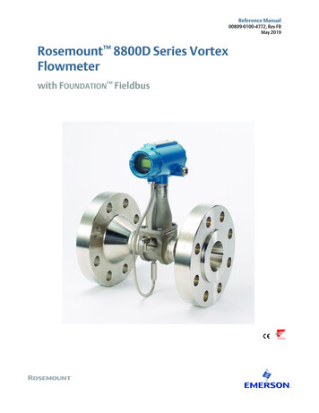
Reference ManualIntroduction00809-0100-4772, Rev FBMay 2019environments. The fieldbus environment is the base level group of digital networks in thehierarchy of plant networks.The fieldbus retains the desirable features of the 4–20 mA analog system, including astandardized physical interface to the wire, bus-powered devices on a single pair of wires,and intrinsic safety options. In addition, it enables the following capabilities:1.3 Increased capabilities due to full digital communications Reduced wiring and wire terminations due to multiple devices on one pair of wires Increased selection of suppliers due to interoperability Reduced loading on control room equipment with the distribution of some controland input/output functions to field devices Speed options for process control and manufacturing applications.System descriptionThe Rosemount 8800D Vortex Flowmeter with FOUNDATION fieldbus consists of a meterbody and transmitter. It measures volumetric flow rate by detecting the vortices created bya fluid passing by the shedder bar.The meter body is installed in-line with process piping. A sensor is located at the end of theshedder bar and creates an alternating sine wave signal due to the passing vortices. Thetransmitter measures the frequency of the signal and converts it into a flowrate.This manual is designed to assist in the installation and operation of the flowmeter.This product is intended to be used as a flowmeter for liquid, gas, or steamapplications. Any use other than for which it was intended may result in serious injuryor death.2Introduction
Configuration and OperationReference ManualMay 201900809-0100-4772, Rev FBSection 2Configuration and OperationOverview . . . . . . . . . . . . . . . . . . . . . . . . . . . . . . . . . . . . . . . . . . . . . . . . . . . . . . . . . . . . . . . .Safety messages . . . . . . . . . . . . . . . . . . . . . . . . . . . . . . . . . . . . . . . . . . . . . . . . . . . . . . . . . .Commissioning . . . . . . . . . . . . . . . . . . . . . . . . . . . . . . . . . . . . . . . . . . . . . . . . . . . . . . . . . . .User interfaces . . . . . . . . . . . . . . . . . . . . . . . . . . . . . . . . . . . . . . . . . . . . . . . . . . . . . . . . . . .General block information . . . . . . . . . . . . . . . . . . . . . . . . . . . . . . . . . . . . . . . . . . . . . . . . .Resource Block . . . . . . . . . . . . . . . . . . . . . . . . . . . . . . . . . . . . . . . . . . . . . . . . . . . . . . . . . . .Transducer Block . . . . . . . . . . . . . . . . . . . . . . . . . . . . . . . . . . . . . . . . . . . . . . . . . . . . . . . . .Analog Input (AI) Function Block . . . . . . . . . . . . . . . . . . . . . . . . . . . . . . . . . . . . . . . . . . . .Flow simulation . . . . . . . . . . . . . . . . . . . . . . . . . . . . . . . . . . . . . . . . . . . . . . . . . . . . . . . . . . .Device capabilities . . . . . . . . . . . . . . . . . . . . . . . . . . . . . . . . . . . . . . . . . . . . . . . . . . . . . . . .2.1page 3page 3page 4page 4page 7page 8page 12page 16page 18page 19OverviewThis section covers operation, software functionality, and configuration procedures for theRosemount 8800D Vortex Flowmeter with FOUNDATION Fieldbus. This section isorganized by block information. For detailed information about the function blocks used inthe flowmeter, refer to the Rosemount FOUNDATION Fieldbus Block Reference Manual.2.2Safety messagesProcedures and instructions in this section may require special precautions to ensure thesafety of the personnel performing the operations. Information that raises potential safetyissues is indicated by a warning symbol ( ). Refer to the following safety messages beforeperforming an operation preceded by this symbol.Explosions can result in death or serious injury. Do not remove the transmitter covers in explosive environments when the circuitis live. Transmitter covers must be fully engaged to meet explosion proof requirements. Before connecting a configuration tool in an explosive atmosphere, make surethe instruments in the loop are installed in accordance with intrinsically safe ornonincendive field wiring practices.Configuration and Operation3
Configuration and OperationReference Manual00809-0100-4772, Rev FBMay 2019Electrical shock can result in death or serious injury. Avoid contact with the leads and terminals. High voltage that maybe present on leads can cause electrical shock.2.3User interfacesThe flowmeter has both DD and DTM -based user interfaces. All device configuration andmaintenance tasks can be performed using either communication technology.Device Descriptors (DDs) and DTM files for Rosemount products are available on theEmerson Install Kits website.The DD capabilities supported will vary based on host supplier and host revision. Checkwith the host supplier to determine and obtain the appropriate DD for your situation. Thetype of DD your host supports may influence navigation between different functions.2.4CommissioningCommissioning the flowmeter consists of verifying the transmitter configuration andoperation. Typically this should be done before the flowmeter is installed in the applicationenvironment. In most cases, the user-supplied variables are pre-configured in thetransmitter at the factory, so the meter is ready to use upon arrival at the end userinstallation.Configuration may be required if: Any configuration variables have changed. A replacement transmitter is being installed.To commission, connect power to the device and connect a Field Communicator orFoundation Fieldbus host system to the signal loop.41.Verify the device powers up and communicates with the Field Communicator orhost system.2.Verify transmitter configuration parameters. Following are typical parameters tocheck: Tag Transmitter Mode Process Fluid Reference K-factor Flange Type Mating Pipe ID PV Units (configured in the AI block)Configuration and Operation
Reference ManualConfiguration and Operation00809-0100-4772, Rev FBMay 2019 Flow Damping Fixed Process Temperature Fixed Process Density and Density Units Density Ratio (for Standard or Normal flow units only)3.If transmitter functional verification is required, refer to Appendix C: ElectronicsVerification.The flowchart in Figure 2-1 is a general guide for commissioning and meter installation. It
Rosemount 8800D Vortex Flowmeter NOTICE Read this manual before working with the product. For personal and system safety, and for optimum product performance, make sure you thoroughly understand the contents before installing, using, or maintaining this product. Within the United States, Emerson Process Management has two toll-free assistance
