Transcription
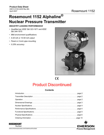
Product Data Sheet00813-0100-4004, Rev KJJuly 2022Rosemount 8800D Vortex FlowmeterIndustry Leading Vortex HART , FOUNDATION Fieldbus, and Modbus RS-485 Protocols All welded, non-clog design provides maximum performance, reliability and enhanced safety by eliminating ports and gaskets. CriticalProcess increases process availability and enhances overall safety. SIL 2/3 Capable: IEC 61508 certified by an accredited 3rd party agency for use in safety instrumented systems up to SIL 3. Available with optional multivariable output. Internal temperature compensation provides cost-effective saturated steam andliquid mass flow measurement. Adaptive Digital Signal Processing (ADSP) provides vibration immunity and flow range optimization. Reducer Vortex extends the measurable flow range, reduces installation costs, and minimizes project risk. Simplified troubleshooting through device diagnostics and meter verification. Available in wafer, flanged, dual, quad, weld end, threaded end, reducer, and high pressure designs.
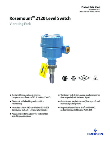
July 2022Product OverviewRosemount 8800 selection guideRosemount 8800 Flanged vortex flow meter Wide range of flange ratings available Ideal for all applications from general purpose to the most demandingapplications Available with ½ inch through 12 inch (15 mm through 300 mm) line sizesRosemount 8800 Reducer vortex flow meter Flanged vortex flow meter with reducing flanges integrated into the design Reduces cost by eliminating the need for field assembly of reduced piping Both reducer and standard vortex have a common face-to-face dimension whichallows the user to change the meter without impacting the piping layout ordrawing Available with 1 inch through 14 inch (25 mm to 350 mm) line sizesContentsProduct Overview. 2Flow rate sizing.10Ordering Information - Single/Dual Transmitter. 11Ordering information – Quad transmitter.19Product Specifications. 28Product certifications. 54Dimensional drawings. 552www.emerson.com/vortex
July 2022Rosemount 8800 MultiVariable vortex flow meter Integral temperature sensor enables temperature compensated mass flow forsaturated steam and liquids Incorporates temperature sensor into the vortex meter using the shedder bar as athermowell, which keeps the vortex and temperature sensors isolated fromprocess for easy verification and replacement Capability to capture a pressure input from a HART pressure device for pressurecompensation mass flow for saturated steam Pressure and Temperature compensation mass flow for Superheated Steam Superheat Diagnostics allows for an alert and/or alarm to activate when degreesof superheat are close to saturated conditions. Available with integrated thermowell for 1½ inch through 12 inch (40 mmthrough 300 mm) Flanged and 2 inch through 12 inch (50 mm through 300 mm)Reducer Vortex meter body sizesRosemount 8800 Wafer vortex flow meter Lightweight, cost-effective solution Easy installation with standard alignment rings Ideal for utility applications Available with ½ inch through 8 inch (15 mm through 200 mm) line sizesRosemount 8800 Weld-end vortex flow meter Flange gaskets are eliminated by welding the flow meter directly into your processpiping The only vortex flow meter available with zero potential leak points Ideal for applications where reducing potential leak points is important Available with ½ inch through 12 inch (15 mm through 300 mm) line sizeswww.emerson.com/vortex3
July 2022Rosemount 8800 Threaded End vortex flow meter Easy installation by matching existing threaded pipe union Reduce cost by eliminating flanged connections Available for ½ inch through 2 inch (15 mm through 50 mm) and 1 inch through2 inch (25 mm through 50 mm) Reducer meter body sizesRosemount 8800 Dual vortex flow meter Flanged vortex flow meter withredundant electronics and sensors Use for SIS and other applicationswhere redundancy is critical Available with ½ inch through 12 inch(15 mm through 300 mm) line sizes4www.emerson.com/vortex
July 2022Rosemount 8800 Quad vortex flow meter Emerson delivers an integrated quadruple sensor configuration providing 2oo3voting plus an addition independent output for process control Reduce installation costs with a simple drop-in solution Decrease operating expenses and maintenance over traditional dP orifice flowmeters Excellent rangeability and no need for zeroing Couple with the CriticalProcess (CPA) option to ensure ultimate safety andreliability Transmitters available with independent configurations Available with 2 inch through 12 inch (50 mm through 300 mm) line sizesThe Rosemount 8800D delivers reliability, safety, and maximum processavailability Rosemount Reliability—The Rosemount 8800D Vortex eliminates impulse lines, ports, and gaskets to improve reliability. Non-clog Design—Unique all welded, gasket-free construction which has no ports or crevices that can clog. SIL 2/3 Capable - The Rosemount 8800D Vortex is certified by an accredited 3rd party agency for use in safety instrumentedsystems up to SIL 3 (minimum requirement of single use [1oo1] for SIL 2 and redundant use [1oo2] for SIL 3). Vibration Immunity—Mass balancing of the sensor system, and Adaptive Digital Signal Processing (ADSP) provide vibrationimmunity. Replaceable Sensor—The sensor is isolated from the process and can be replaced without breaking the process seal. All line sizesuse the same sensor design allowing a single spare to serve every meter. Simplified Troubleshooting—Device Diagnostics enable field verification of meter electronics and sensor without processshutdown.www.emerson.com/vortex5
July 2022The Rosemount 8800D Critical Process Vortex increases process availability andenhances overall safetyEliminate bypass piping for critical process installationsTraditional vortex installations in critical applications include a bypass line to allow process fluid to be re-directed around the vortexflow meter during routine sensor maintenance. Rosemount's unique non-wetted sensor can be installed without bypass piping,even in the most difficult process environments.Improve process availabilityEliminate the need to shut down the process during routine maintenance and meter verification.Enhances safety in hazardous process fluid applicationsA Critical Process Valve (CPA option) enables access to the sensor cavity to verify that no process fluid is present.6www.emerson.com/vortex
July 2022Boost reliability, confidence, and control while reducing safety risks,maintenance costs, and down time in liquid and steam flow applications with the Rosemount 8800D MultiVariable flowmeterGain confidence in your mass flow measurement accuracyEmerson MultiVariable Vortex provides the highest level of accurate steam mass flow over the widest range using an externalpressure and/or internal temperature measurement to capture your dynamic operating conditions. This delivers the confidencerequired for your billing statements and also achieves better control in steam applications.Reduce safety risks and maintenance burdens associated with many-component measurement solutionsBy selecting Emerson MultiVariable Vortex, the safety risk to operators is reducing while at the same time, the maintenancerequired is reduced and simplified. The plant area shutdown requirements are reduced while performing maintenance orverification tasks, which also reduces the cost implications of being offline.Overcome challenges of steam mass-flow measurement with a more durable solutionEmerson MultiVariable Vortex delivers the performance confidence and system reliability required in steam applications. Costimplications related to poor quality steam, complex system architecture and process shutdowns are eliminated by reducingvulnerability to leakage, clogging, plugging and freezing.www.emerson.com/vortex7
July 2022Reduced installation complexity with the Remote TransmitterFor installations where the transmitter must be located remotely from the sensor, two remote cable styles are available: Standard cable can be used for applications where environmental or physical damage is unlikely, or if the cable will be enclosedin conduit. Armored cable should be used when maximum reliability or resistance to environmental and physical damage are a concern.Cable glands of appropriate metal type are provided.Both cable types are offered in standard lengths (10, 20, 33, 50, and 75 ft [3, 6, 10, 15, and 23 meters]). Standard cable can also beordered in custom lengths.8www.emerson.com/vortex
July 2022Detect process fluid change from liquid to gas with SMART Fluid DiagnosticsOil and gas separators Remotely detect when your separator dump valve allows gas to pass through your water dump leg. Selectable alert modes (digital, analog or pulse) signal when gas flow is detected.Steam, nitrogen, or air blow down Control your clean in place (CIP) or blow down cycles with a single meter that measures the flow rate of your primary processfluid as well as the change from liquid to gas flow. Set your control system to control down cycle based on alert from in-line vortex meter. Selectable alert modes (digital, analog or pulse) signal when gas flow is detected.www.emerson.com/vortex9
July 2022Provide comparison to external time reference with Elapsed Time MeterHILOALARM Running totalizer of hours of operation Accuracy 1 hour per year maximum deviationSECURITYONOFFAccess process variables and diagnostics locally with the optional LCD RMSECURITYSECURITYOFFONOFFONOFFThe optional 11 digit, two-line integral LCD display can be configured to alternate between selected display options,such as flow,totalizer, mA output, temperature (MTA/MCA) and pressure (MPA/MCA). Diagnostics and fault conditions, when present, will alsoappear on the display for local troubleshooting.Access information when you need it with asset tagsNewly shipped devices include a unique QR code asset tag that enables you to access serialized information directly from thedevice. With this capability, you can: Access device drawings, diagrams, technical documentation, and troubleshooting information in your MyEmerson account Improve mean time to repair and maintain efficiency Ensure confidence that you have located the correct device Eliminate the time-consuming process of locating and transcribing nameplates to view asset information.Flow rate sizingSizing calculations are required to select the proper flow meter size. These calculations provide pressure loss, accuracy, minimumand maximum flow rate data to guide in proper selection. Vortex sizing software can be found using the Selection and Sizing tool.The Selection and Sizing tool can be accessed online or downloaded for offline use using this link:www.Emerson.com/FlowSizingFor reference for typical flow rates for common applications, please see Typical flow rates or refer to product reference manual00809-0100-4004 or 00809-1100-4004.10www.emerson.com/vortex
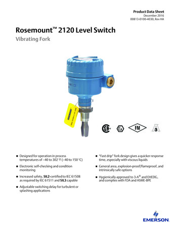
July 2022Ordering Information - Single/Dual TransmitterModel code structureIn conjunction with a complete model code string, we strongly recommend every meter be configured at the factory for yourapplication. Use the Rosemount 8800D Configuration Data Sheet (00806-0100-4004) to convey your configuration information tothe factory.Figure 1: Guide to model code structure8800DAA.B.C.D.E.F.G.H.I.J.D1M5MTAQ4Q8B C D E F G HIJF020SA1N1ModelMeter styleLine sizeWetted materialProcess connection & pressure ratingSensor process temperature rangeHousing material & conduit entriesOutput optionsCalibrationOptionsExample model code with one selection out of each required category:8800D F 020 S A1 N 1 D 1 M5 MTA Q4 Q8The starred ( ) offerings represent the best delivery options.www.emerson.com/vortex11
July 2022RequirementsTable 1: Requirements - select one from each available choiceCodeDescriptionBase modelVortex Flow Meter FStandard body style for use with flanged, welded, and threaded process connections WWafer body style for use with wafer-style process connections RReducer – Meter body is one nominal size smaller than line size selection for use with flanged orthreaded process connections D(1)Dual-sensor for use with flanged, welded, and threaded process connections8800DMeter styleLine size005(2)½ inch (15 mm) 0101 inch (25 mm) 0151½ inch (40 mm) 0202 inch (50 mm) 0303 inch (80 mm) 0404 inch (100 mm) 0606 inch (150 mm) 0808 inch (200 mm) 10010 inch (250 mm)12012 inch (300 mm)140(3)14 inch (350 mm)Wetted materialsS316 wrought stainless and CF-3M cast stainless; Material of construction is 316/316L.H(4)UNS N06022 wrought nickel alloy; CW2M cast nickel alloy.CA105 forged carbon steel and WCB cast carbon steelLLF2 forged carbon steel and LCC cast carbon steelD(5)UNS S32760 wrought duplex stainless steel and 6A cast duplex stainless steel Process connection style and pressure ratingA1ASME B16.5 RF Class 150 A3ASME B16.5 RF Class 300 A6ASME B16.5 RF Class 600A7(6)ASME B16.5 RF Class 900A8(7)ASME B16.5 RF Class 1500K0EN 1092-1 PN 10 Type B1K1EN 1092-1 PN 16 (PN 10/16 for wafer style) Type B1K2EN 1092-1 PN 25 Type B112 www.emerson.com/vortex
July 2022Table 1: Requirements - select one from each available choice (continued)CodeDescriptionK3EN 1092-1 PN 40 (PN 25/40 for wafer style) Type B1K4EN 1092-1 PN 63 Type B1K6EN 1092-1 PN 100 Type B1K7(6)EN 1092-1 PN 160 Type B1K8(7)EN 1092-1 PN 250 Type B1B1(8)ASME B16.5 RTJ Class 150 for flange-style onlyB3ASME B16.5 RTJ Class 300 for flange-style onlyB6ASME B16.5 RTJ Class 600 for flange-style onlyB7(6)ASME B16.5 RTJ Class 900 for flange-style onlyB8(7)ASME B16.5 RTJ Class 1500 for flange-style onlyC1ASME B16.5 RF Class 150, smooth finishC3ASME B16.5 RF Class 300, smooth finishC6ASME B16.5 RF Class 600, smooth finishC7(6)ASME B16.5 RF Class 900, smooth finishC8(7)ASME B16.5 RF Class 1500, smooth finishJ1JIS 10KJ2JIS 20KJ4JIS 40KL0EN 1092-1 PN 10 Type B2L1EN 1092-1 PN 16 (PN 10/16 for wafer style) Type B2L2EN 1092-1 PN 25 Type B2L3EN 1092-1 PN 40 (PN 25/40 for wafer style) Type B2L4EN 1092-1 PN 63 Type B2L6EN 1092-1 PN 100 Type B2L7(6)EN 1092-1 PN 160 Type B2M0EN 1092-1 PN 10 Type D for flange style onlyM1EN 1092-1 PN 16 Type D for flange style onlyM2EN 1092-1 PN 25 Type D for flange style onlyM3EN 1092-1 PN 40 Type D for flange style onlyM4EN 1092-1 PN 63 Type D for flange style onlyM6EN 1092-1 PN 100 Type D for flange style onlyM7(6)EN 1092-1 PN 160 Type D for flange style onlyN0EN 1092-1 PN 10 Type FN1EN 1092-1 PN 16 Type FN2EN 1092-1 PN 25 Type Fwww.emerson.com/vortex 13
July 2022Table 1: Requirements - select one from each available choice (continued)CodeDescriptionN3EN 1092-1 PN 40Type FN4EN 1092-1 PN 63 Type FN6EN 1092-1 PN 100 Type FN7(6)EN 1092-1 PN 160 Type FT8(9)Threaded End process connections, NPT, Schedule 80ST9(10)Threaded End process connections, NPT, Schedule 160SW1(11)Weld-end, Schedule 10SW4(11)Weld-end, Schedule 40SW8(8)(11)Weld-end, Schedule 80SW9(11)Weld-end, Schedule 160SSensor process temperature rangeN(12)Standard: –40 to 450 F (–40 to 232 C) E(12)Extended: –330 to 800 F (–200 to 427 C) S(12)Severe service: –330 to 842 F (–200 to 450 C) and nickel alloy construction for increasedcorrosion resistance Housing material and conduit entries1Aluminum housing, two ½–14 NPT conduit entries 2(13)Aluminum housing, two M20 x 1.5 conduit entries 3(13)Aluminum housing, two PG 13.5 conduit adapters 4Aluminum housing, one G1/2 conduit adapter (one conduit entry) 5Aluminum housing, two G1/2 conduit adapters (two conduit entries) 6Stainless steel housing, two ½–14 NPT conduit entries7(13)Stainless steel housing, two M20 x 1.5 conduit entriesOutputsD4–20 mA digital electronics (HART protocol) P4–20 mA digital electronics (HART protocol) with scaled pulse F(14)(15)FOUNDATION Fieldbus digital signal M(14)(15)Modbus RS-485 (device status and 4 dynamic variables) Flow calibration Calibration1(1)(2)(3)(4)(5)14Duals from ½ inch through 4 inch (15 mm through 100 mm) have dual bar meter body design. Duals from 6 inch through 12 inch (150 mmthrough 350 mm) have single bar meter body design. Please contact an Emerson Flow representative (see back page) for more information on 2inch through 4 inch (50 mm to 100 mm) on single bar dual meter body design.Not available for Rosemount 8800DR.Code 140 (14 inch [350 mm]) size is only available with reducer.See Table 15 for collared vs. weld neck flange configuration.Available in Flanged and Dual from 6 inch through 12 inch and Reducer from 8 inch through 12 inch Class 1500 in 6 inch and 8 inch meter bodysizes and Class 900 in 10 inch through 12 inch meter body sizes.www.emerson.com/vortex
July 2022(6)(7)(8)(9)(10)(11)(12)(13)(14)(15)Available on flanged and dual style meters from ½ inch through 8 inch (15–200 mm) and reducer style meters from 1 inch through 8 inch (25–200 mm). Also available in 10 inch through 12 inch (250-300 mm) flanged and dual meters along with 12 inch (300 mm) reducers when usingSuper Duplex material of construction.Only available for flange and dual style meters from 1 inch through 8 inch (25–200 mm).Not available with ½ inch line size.Available with Meter style code F and D from ½ inch through 2 inch (15 mm through 50 mm) line sizes and Meter style code R (reducer) in 1 inch(25 mm) line sizes with Wetted materials codes S and D.Available in Meter style code F and D from ½ inch through 2 inch (15 mm through 50 mm) line sizes and Meter style code R (reducer) in 1½ inchand 2 inch (40 mm and 50 mm) line sizes with Wetted materials codes S and D.Only available with Meter Style F or D.See Table 10 and Table 14 for the specific sensor process temperature range. Meters that include the PD option code are compliant with the EUPressure Equipment Directive, PED, 2014/68/EU and the UK Pressure Equipment (Safety) Regulation, PER, Statutory Instrument, SI No. 1105.No Japan (E4) approval.The Safety Certifications SI option code is not available with this option.MultiVariable option codes MPA and MCA not available with this option.OptionsSelect only as needed.Table 2: OptionsCodeDescriptionHazardous area approvalsE5US Approvals Explosion-proof and Dust Ignition-proof I5US Approvals Intrinsically Safe and Non-Incendive IE(1)US Approvals FISCO Intrinsically Safe and Non-Incendive K5US Approvals Explosion-proof, Dust Ignition-proof, Intrinsically Safe, and Non-Incendive E6US/Canadian Approvals Explosion-proof and Dust Ignition-proof I6US/Canadian Approvals Intrinsically Safe and Division 2 IF(1)US/Canadian Approvals FISCO Intrinsically Safe and Division 2 K6US/Canadian Approvals Explosion-proof, Dust Ignition-proof, Intrinsically Safe, and Division 2 KBUS/Canadian Approvals Explosion-proof, Dust Ignition-proof, Intrinsically Safe, and Division 2 E1ATEX Flameproof I1ATEX Intrinsic Safety ia; Intrinsic Safety ic IA(1)ATEX FISCO Intrinsic Safety N1ATEX Type n NDATEX Dust K1ATEX Flameproof; Intrinsic Safety; Type n; Dust E7IECEx Flameproof I7IECEx Intrinsic Safety IG(1)IECEx FISCO Intrinsic Safety N7IECEx Type n NFIECEx Dust K7IECEx Flameproof; Intrinsic Safety; Type n; Dust E2INMETRO Flameproof I2INMETRO Intrinsic Safety www.emerson.com/vortex15
July 2022Table 2: Options (continued)CodeDescriptionIB(1)INMETRO FISCO Intrinsic Safety K2INMETRO Flameproof; Intrinsic Safety E3China Flameproof I3China Intrinsic Safety N3China Type n IH(1)China FISCO/FNICO Intrinsic Safety K3China Flameproof; Dust; Intrinsic Safety; Type n E4Japan Flameproof E8Technical Regulations Customs Union (EAC) Flameproof I8Technical Regulations Customs Union (EAC) Intrinsic Safety N8Technical Regulations Customs Union (EAC) Type n K8Technical Regulations Customs Union (EAC) Flameproof; Intrinsic Safety; Type n G8Technical Regulations Customs Union (EAC) FISCO Intrinsic Safety MTA(2)(3)MultiVariable output with temperature compensation and integral temperature sensor MPA(2)(4)(5)MultiVariable output with pressure compensation MCA(2)(3)(4)(5)MultiVariable output with pressure and temperature compensation and integral temperaturesensor LCD indicator MultiVariableDisplay typeM5Remote electronicsR10Remote electronics with 10 ft (3,0 m) cable R20Remote electronics with 20 ft (6,1 m) cable R30Remote electronics with 30 ft (9,1 m) cable R33Remote electronics with 33 ft (10,1m) cable R50Remote electronics with 50 ft (15,2 m) cable R75Remote electronics with 75 ft (22,9 m) cable RxxRemote Electronics with customer-specified cable length (xx ft., 1 ft to 75 ft cable in 1 ftincrements)Example: R15 15 ft, R34 34 ftA10Armored remote electronics with 10 ft (3,0 m) cableA20Armored remote electronics with 20 ft (6,1 m) cableA33Armored remote electronics with 33 ft (10,1 m) cableA50Armored remote electronics with 50 ft (15,2 m) cableA75Armored remote electronics with 75 ft (22,9 m) cable16www.emerson.com/vortex
July 2022Table 2: Options (continued)CodeDescriptionTransient protectionTransient Protection terminal block C4(6)NAMUR alarm and saturation values, high alarm CN(6)NAMUR alarm and saturation values, low alarm Cleaning for special services T1Alarm modeSpecial cleaningP2Ground screw assemblyV5(7)External ground screw assembly Plantweb control functionalityA01(8)Basic Control: One Proportional/Integral/Derivative (PID) Function Block ASME B31.1 code compliance(9)J2ASME B31.1 General complianceJ7ASME B31.1 Boiler External Piping (BEP) code stampConduit electrical connectorsGE(10)(5)M12, 4-pin, Male Connector (eurofast )GM(10)(5)A size Mini, 4-pin, Male Connector (minifast )GN(5)ATEX Flameproof A size, Mini 4-pin male connector (minifast)HART revision configurationHR7(4)(5)HART Revision 7 Process diagnosticsDS3(2)(4)(5)Smart Fluid Diagnostics Safety certificationsSafety Certification of 4–20 mA Output per IEC 61508 Q4Calibration Certificate per ISO 10474 3.1/EN 10204 3.1 Q5Hydrostatic Test Certificate Q8Material Traceability per ISO 10474 3.1/EN 10204 3.1 QPCalibration Certificate per ISO 10474 3.1/EN 10204 3.1 and Tamper Evident Seal Q25Certificate of Compliance to NACE MR0175 and MR0103 Q66Weld procedure package (weld map, weld procedure specification, weld procedure qualificationrecord, welder performance qualification) Q70(11)NDE Weld Examination Inspection Certificate, ISO 10474 3.1; see Table 28Q71(11)NDE Weld Examination Inspection Certificate, ISO 10474 3.1 with images; see Table 28Q76Positive Material Identification (PMI) on Flanges and Pipe (XRF), per ASTM E1476-97; see Table 29.SI(4)(5)Quality certificatewww.emerson.com/vortex 17
July 2022Table 2: Options (continued)CodeDescriptionQ77Positive Material Identification (PMI) with Carbon Content on Flange and Pipe (OES) per ASTME1476-97; see Table 30. Q80(12)Ferrite Content Testing (FN 3 to 10) Sensor completionWGWitness GeneralPressure Equipment Directive (PED)PD Pressure Equipment Directive (PED)Shipboard approvalsSBS(13)American Bureau of Shipping (ABS) type approval SBV(13)Bureau Veritas (BV) type approval SDN(13)Det Norske Veritas (DNV) type approval Critical process vortexCPACritical Process Online Sensor ReplacementNot available on: Any wafer-style meter (Meter style code W) Any ½ inch (15 mm) flange (Meter style code F) or 1 inch (25 mm) reducer (Meter syle code R) 1 inch (25 mm) flange (Meter style code F) or 1½ inch (40 mm) reducer (Meter style code R)with JIS 10K, EN PN40, or PN16 flange rating Meters with Wetted Material option code D 6 inch (150 mm) or larger meters with Wetted Material option code HElapsed time meterETM(4)(5)Elapsed time meter Quick Start Guide language (default is English)YFFrench YGGerman YIItalian YJJapanese YKKorean YMChinese (Mandarin) YPPortuguese YRRussian YSSpanish (1)(2)(3)(4)(5)18Fieldbus Intrinsic Safe Concept (FISCO) available with output code F (Foundation Fieldbus digital signal) only.The Safety Certifications SI option code is not available with this option.Available with Rosemount 8800DF from 1½ inch through 12 inch (40 mm through 300 mm). Available with 8800DR from 2 inch through 12 inch(50 mm through 300 mm). Consult an Emerson Flow representative (see back page) for line sizes smaller than 1½ inch (40 mm). Not availablewith 8800DW or 8800DD.Output option code F not available with this option.Output option code M not available with this option.www.emerson.com/vortex
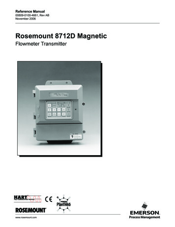
July 2022(6)(7)(8)(9)(10)(11)NAMUR compliant operation and the alarm latch options are preset at the factory and can be changed to standard operation in the field.Only available for ordinary location. The ground screw is included by default for all hazardous area approvals.Requires output code F.Requires Quality Certificate Q4, Q5, Q8, and NDE Welding Certificate Q70 or Q71.Not available with certain hazardous location certifications. Contact an Emerson Flow representative for details (see back page).Available with material option codes S, C, L and H; not available with Meter Style option code W in 1 inch through 4 inch (25 mm through100 mm) line sizes.(12) Only available with Material option code S.(13) Not available with Output option code M.Ordering information – Quad transmitterModel code structureThe outputs and hazardous approvals must be specified for each of the four transmitters on a quad transmitter vortex flow meter.As a result, the model code string in those two sections has an entry for each transmitter. The model code string for all otherrequirements and options has only a single entry applicable to the entire meter. We strongly recommend that every meter, andeach transmitter, be configured at the factory for your application. Use the Rosemount 8800D Quad Configuration Data Sheet(00806-1100-4004) to convey your configuration information to the factory. Example model code with one selection out of eachrequired category:www.emerson.com/vortex19
July 2022Figure 2: Guide to model code 1I5I5I5I5M5R30SI1SI2SI3Q4Q5Q8CPAHIJKB C D E F GModelMeter styleLine sizeWetted materialProcess connection & pressure ratingSensor process temperature rangeHousing material & conduit entriesOutput options (each transmitter)CalibrationHazardous area approvals (each transmitter)OptionsExample model string: 8800DQ 060 S A3 E 1 DDDF 1 I5I5I5IE M5 R30 SI1 SI2 SI3 Q4 Q5 Q8 CPAThe starred ( ) offerings represent the best delivery options.RequirementsTable 3: Requirements - select one from each available choiceCodeDescriptionBase modelVortex Flow Meter Quad transmitter (two shedder bars and four transmitters), flanged 020(1)2 inch (50 mm) 030(1)3 inch (80 mm) 040(1)4 inch (100 mm) 0606 inch (150 mm) 0808 inch (200 mm)10010 inch (250 mm)12012 inch (300 mm)8800DStyleQLine sizeWetted materialsS316 wrought stainless and CF-3M cast stainless; Material of construction is 316/316L.HUNS N06022 wrought nickel alloy; CW2M cast nickel alloy; weld neck flangeCA105 forged carbon steel and WCB cast carbon steelLLF2 forged carbon steel and LCC cast carbon steelD(2)UNS S32760 wrought duplex stainless steel and 6A cast duplex stainless steel20 www.emerson.com/vortex
July 2022Table 3: Requirements - select one from each available choice (continued)CodeDescriptionProcess connection style and pressure ratingA1ASME B16.5 RF Class 150 A3ASME B16.5 RF Class 300 A6ASME B16.5 RF Class 600A7(3)ASME B16.5 RF Class 900A8(4)ASME B16.5 RF Class 1500K0EN 1092-1 PN 10 Type B1K1EN 1092-1 PN 16 Type B1K2EN 1092-1 PN 25 Type B1K3EN 1092-1 PN 40 Type B1K4EN 1092-1 PN 63 Type B1K6EN 1092-1 PN 100 Type B1K7(3)EN 1092-1 PN 160 Type B1B1ASME B16.5 RTJ Class 150B3ASME B16.5 RTJ Class 300B6ASME B16.5 RTJ Class 600B7(3)ASME B16.5 RTJ Class 900B8(4)ASME B16.5 RTJ Class 1500C1ASME B16.5 RF Class 150, smooth finishC3ASME B16.5 RF Class 300, smooth finishC6ASME B16.5 RF Class 600, smooth finishC7(3)ASME B16.5 RF Class 900, smooth finishC8(4)ASME B16.5 RF Class 1500, smooth finishJ1JIS 10KJ2JIS 20KJ4JIS 40KL0EN 1092-1 PN 10 Type B2L1EN 1092-1 PN 16 Type B2L2EN 1092-1 PN 25 Type B2L3EN 1092-1 PN 40 Type B2L4EN 1092-1 PN 63 Type B2L6EN 1092-1 PN 100 Type B2L7(3)EN 1092-1 PN 160 Type B2www.emerson.com/vortex 21
July 2022Table 3: Requirements - select one from each available choice (continued)CodeDescriptionM0EN 1092-1 PN 10 Type DM1EN 1092-1 PN 16 Type DM2EN 1092-1 PN 25 Type DM3EN 1092-1 PN 40 Type DM4EN 1092-1 PN 63 Type DM6EN 1092-1 PN 100 Type DM7(3)EN 1092-1 PN 160 Type DN0EN 1092-1 PN 10 Type FN1EN 1092-1 PN 16 Type FN2EN 1092-1 PN 25 Type FN3EN 1092-1 PN 40Type FN4EN 1092-1 PN 63 Type FN6EN 1092-1 PN 100 Type FN7(3)EN 1092-1 PN 160 Type FW1Weld-end, Schedule 10SW4Weld-end, Schedule 40SW8Weld-end, Schedule 80SW9Weld-end, Schedule 160SSensor process temperature rangeN(5)Standard: –40 to 450 F (–40 to 232 C) E(5)Extended: –330 to 800 F (–200 to 427 C) S(5)Severe service: –330 to 842 F (–200 to 450 C) and nickel alloy construction for increasedcorrosion resistance Housing materia
The Rosemount 8800D delivers reliability, safety, and maximum process availability Rosemount Reliability—The Rosemount 8800D Vortex eliminates impulse lines, ports, and gaskets to improve reliability. Non-clog Design—Unique all welded, gasket-free construction which has no ports or crevices that can clog.