Transcription
KNCT2-808KNSeriesGas-fired direct ventCast iron boilersModels KN-6, -10, -20 only(HeatNet control firmware edition 2.45 )Control manualControl adjustment andOperation instructionsAlso read and follow:KN Series Gas BoilerInstallation & OperationInstructionsThis manual is intended only for use by a qualified heating installer/technician. Read and follow this manual, all supplements and relatedinstructional information provided with the boiler. Install, start and service the boiler only in the sequence and methods given in theseinstructions. Failure to do so can result in severe personal injury, death or substantial property damage.Do not use the boiler during construction. Construction dust and particulate, particularly drywall dust, will cause contamination ofthe burner, resulting in possible severe personal injury, death or substantial property damage. The boiler can only be operated with a dustfree air supply. Follow the instruction manual procedures to duct air to the boiler air intake. If the boiler has been contaminated by operationwith contaminated air, follow the instruction manual guidelines to clean, repair or replace the boiler if necessary.Affix these instructions near to the boiler. Instruct the building owner to retain the instructions for future use by a qualified servicetechnician, and to follow all guidelines in the User’s Information Manual.P/N 42-9534 8/08 Copyright 2008 Hydrotherm
KN-SERIES GAS-FIRED DIRECT VENT CAST IRON BOILERS – CONTROL MANUALHydrotherm KN-Series boilers — HeatNetTM controlControl overviewThe KN HeatNet control monitors boiler temperature and limit circuit inputs, modulating boiler firingrate to meet demand. The control uses microprocessor electronics, watching time-average response fromthe system to anticipate how much heat the system needs. Coupled with the five-to-one turndown of theKN boiler, this results in maximum possible condensing-mode operation. The KN boiler will provideunmatched seasonal efficiency.The HeatNet platformHeatNet controls are designed to provide an integrated boiler management system on every boiler. Theplatform provides multiple levels of selectivity. HeatNet electronics can be operated as a simple singleboiler control, while still providing intelligent regulation of boiler firing rate to match system demand.With a few key strokes on the key pad, the HeatNet control can operate as a sophisticated multiple-boilercontroller, using simple RJ45 cable interfacing between units. The control can even accept external controlcommands from building managements systems (Modbus standard, with optional bridge for BACnet orLonWorks) or 20-milliamp analog input from an external controller.The control method used by the HeatNet control is based on digital communications, which eliminates theneed for analog control signals. Analog signal inputs are supported, but a higher level of control precision,repeatability and feedback is gained with digital communications.The HeatNet control can be versatile, providing for operation in multiple ways: As a stand-alone boiler, either modulating, two-stage or ON/OFF.As a boiler in a boiler network, using the on-board HeatNet protocol.As a member boiler in a boiler management system (either directly managed by BMS or managed bya MASTER HeatNet boiler that communicates with the BMS).As a member of a remotely-controlled boiler network (4 – 20-milliamp regulation).Setpoint can be determined by the HeatNet control or by a 4 – 20-milliamp input signal.Network boilers can be operated by override commands for increased versatility.This manual is arranged so the instructions for each of the methods above is self-contained. See the Tableof contents for selection and location.PID responseThe HeatNet control uses proportional-integral-derivative calculations to determine the response toboiler water temperature changes. This means it not only looks at how far away the water temperature isfrom the setpoint temperature, but how fast the temperature is changing and how it has responded overtime. This ensures the boiler won’t make sudden unnecessary changes in firing rate.External limit monitoring & annunciationIn addition to controlling the boiler, the KN HeatNet control monitors external limits wired into thelimit circuit connections. The control shuts down the boiler if a limit opens, and the digital display showswhich limit failed. Monitored limits include high limit aquastat, low water cutoff, flow, ignition controlfault, gas valve alarm and other optional or user-selectable limits.KNHeatNetElectrical enclosureMultiple boiler operationThe HeatNet control easily interfaces with other HeatNet controls. Multiple boiler operation usingHeatNet protocol only requires RJ45 cables daisy-chained from boiler to boiler and a few key strokessetting up control behavior. The master boiler is automatically selected by connecting a sensor lead to itsSYS/DHW HEADER sensor terminals. The HeatNet control recognizes the sensor and configures theboiler as the master. Other boilers only need to have an address assigned.Among the advanced design features of the HeatNet control is the MOD-MAX setting. This limits thefiring rate of all boilers to a pre-set maximum (70% by default). This means all of the boilers will be runat a very efficient level until all boilers are on. Only then can firing rate increase above this setting. Boilerrotation can be first-on/first-off, first-on/last-off, or true rotation (the HeatNet control monitors the totalon time of all boilers, and rotates their usage so the total on time is the same for all).2P/N 42-9534 8/08 Copyright 2008 Hydrotherm
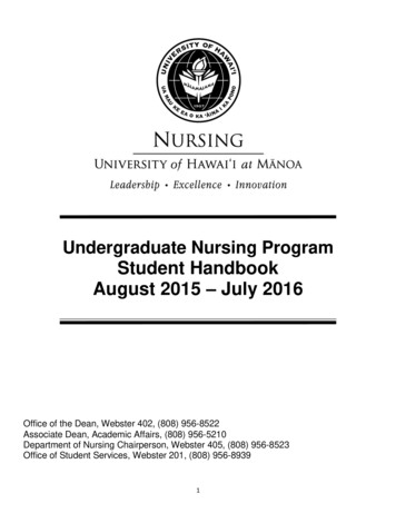
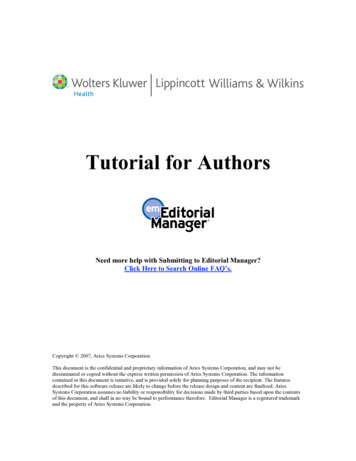
KN-SERIES GAS-FIRED DIRECT VENT CAST IRON BOILERS – CONTROL MANUALHydrotherm KN-Series boilers — HeatNetTM controlElectricalcomponents1.Electrical enclosure2.Control panel — 4-linedigital display andnavigation buttons3.Electrical connection panel4.Electrical subpanel5.Power connection stripfor KN-6 and KN-10—(120v/1/60)6.Power connectionstrip for KN-20 —(208/230/240 VAC/1/60)7.Flame safeguard (Honeywell)8.VFD blower speed controller9.On/off switch658247391KNHeatNetElectrical enclosureP/N 42-9534 8/08 Copyright 2008 Hydrotherm3
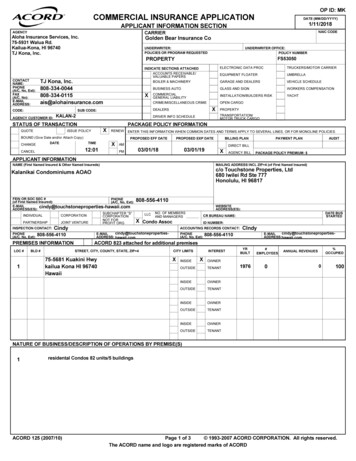
KN-SERIES GAS-FIRED DIRECT VENT CAST IRON BOILERS – CONTROL MANUALThe Mestek KN boiler — with HeatNetTM control1 Stand-alone boiler . . . . . . . . . . . . . . . . . . . . . . . page 6 Provide an external contact connected across J12A HEAT DEMAND terminalsto start the boiler. (A MEMBER boiler in a network can also be activated by closingthe circuit across HEAT DEMAND.) The boiler can operate based on its SUPPLY temperature, or can be operated by remotecontrol from a 4-20mA source. And setpoint temperature can be controlled locallyor by 4-20mA signal from a remote source. The boiler’s T1/T2 terminals can be used to operate the boiler as two-stage (firedat minimum input or maximum input). The AA terminals can be used to fire the boiler as ON/OFF at maximum input.2 Multiple boilers: HeatNet modulation . . . . . page 8 The KN HeatNet control can control up to (16) KN boilers using built-in softwareand hardware. KN boilers come standard with HeatNet communications capability, and requireonly RJ45 HeatNet cables (or shielded wires) to connect between them. The header water temperature setpoint can be set by the master boiler or by a4-20ma input from an external controller. Member boilers can override master boiler control if they receive a contact closureon the HEAT DEMAND terminals or the AA high fire terminals. In addition, thecontrols can be set up to allow priority override by a remote 4-20mA source.3 Multiple boilers: BMS operation . . . . . . . . .page 134 Combined BMS/HeatNet operation — This method uses the KN control’s built-incommunications capabilities to accept MODBUS protocol inputs from a buildingmanagement system. The master boiler control sequences and modulates the boilernetwork to accomplish the demands from the building management system. Direct BMS control of all boilers — Each boiler can be operated directly by theBMS (each boiler will require an optional bridge if using BACnet or LONWORKS).KNHeatNet Boiler setup is essentially the same as for method 2, with the exception that eachboiler must be assigned both a HeatNet network address and an address for theMODBUS interface.Control panel An additional bridge is required to interface with systems using BACnet or LONWORKS protocol. The master boiler will take control and regulate the boiler network if signal fromthe BMS is lost or times out.P/N 42-9534 8/08 Copyright 2008 Hydrotherm
KN-SERIES GAS-FIRED DIRECT VENT CAST IRON BOILERS – CONTROL MANUALContents4 External 4-20ma control . . . . . . . . . . . . . . . . .page 15 4-20mA/HeatNet combined operation — The master boiler can receive the 4-20mAmodulation signal and control the other boilers. 4-20mA direct operation — Up to 5 boilers can be controlled by an external controlthat provides a 4-20ma input signal. The external controls must also activate eachboiler by closing a contact across the boiler’s 4-20ma Remote Enable contacts. Member boilers can override external boiler control if they receive a contact closureon the Heat Demand or any terminal higher priority than the 4-20mA (controlscan be set up to make 4-20mA the highest priority if desired).5 Control menus and adjustments . . . . . . . . .page 24 Operating parameters and control behaviors are set using the KN control’s display/keypad interface. Refer to this section for the menu structure and explanations of the setup options. Table 7 — SETUP menus . . . . . . . . . . . . . . . . . . . . . . . . . . . . . . . . . . . . . . . . . . . . . . . . . . page 25 Table 8 — ADVANCED SETUP menus . . . . . . . . . . . . . . . . . . . . . . . . . . . . . . . . . . page 28 Table 9 — Setup menus — parameter explanations . . . . . . . . . . . . . . . . . . . . . . page 306 Wiring . . . . . . . . . . . . . . . . . . . . . . . . . . . . . . . . . .page 24 Wire the boilers as described in this section.7 Boiler operation and status display. . . . . . .page 24 This section describes control start-up and operation.8 Troubleshooting . . . . . . . . . . . . . . . . . . . . . . . .page 44KNHeatNetElectrical connectionpanel & subpanel Table 10 — Status screen fault displays . . . . . . . . . . . . . . . . . . . . . . . . . . . . . . . . . . . . page 42 Table 11 — Troubleshooting suggestions . . . . . . . . . . . . . . . . . . . . . . . . . . . . . . . . . page 459 Setup worksheet . . . . . . . . . . . . . . . . . . . . . . . .page 48 P/N 42-9534 8/08 Copyright 2008 HydrothermUse this section to enter setup information.5
KN-SERIES GAS-FIRED DIRECT VENT CAST IRON BOILERS – CONTROL MANUAL1Stand-alone boilerWiringElectricalshockhazard—Disconnect all electrical power sourcesto the boiler before making any electricalconnections.Label all wires prior to disconnectionwhen servicing controls. Wiring errorscan cause improper and dangerousoperation! Verify proper operation afterservicing.Failure to comply with the above couldresult in severe personal injury, death orsubstantial property damage.Close the external manual gas valveon every boiler before proceeding. DONOT open any gas valve, or attemptto fire the boiler, until the boilers hasbeen set up and verified following theinstructions in the KN Series Gas BoilerInstallation & Operating Instructions.Failure to comply could cause a boilerfailure, leading to possible severe personalinjury, death or substantial propertydamage.The electrical connections to this boilermust be made in accordance with allapplicable local codes and the latestrevision of the National Electrical Code,ANSI /NFPA-70. Installation shouldalso conform to CSA C22.1 CanadianElectrical Code Part I if installed inCanada. Install a separate 120 volt 15amp circuit for the boiler. A properlyrated shut-off switch should be located atthe boiler. The boiler must be groundedin accordance with the authority havingjurisdiction, or if none, the latest revisionof the National Electrical Code, ANSI/NFPA-70.Line voltage field wiring of any controlsor other devices must use copperconductors with a minimum sizeof #14 awg. Use appropriate wiringmaterials for units installed outdoors.1. See page 16 for wiring information and wiring diagrams.2. Note that the boiler can be wired for override operation.The wiring section provides information on override priorities and options.3. The boiler can be activated by the HEAT DEMAND input,and allowed to modulate based on the HeatNet control. Itcan also be activated by either: ON/OFF full input operation by closing the AA terminals. Operation via remote 4-20mA signal by closing the4-20mA ENABLE terminals and providing the4-20mA signal. Two-stage fired by using the T1 and T2 terminals. Closing one of these brings the boiler on at MIN firing rate.Closing the other brings the boiler to MAX input.Set control parametersBefore turning boilers on to set parameters,disconnect all call for heat wiring at the electricalconnection boards. This will prevent the boilerfrom attempting to cycle during the setup process.1. See Table 1 for a list of parameters that should be set for astand-alone boiler.2. See “Control menus and adjustments,” beginning onpage 24 for a complete list of control parameters and explanations (Table 7, page 25 and Table 8, page 28).3. Carefully read the parameter explanations in Table 9, page 30.4. When adjusting the limit band, operating limit (OP LIMIT),local setpoint (LOC SETPOINT) or system/header(SYS/DHW HEADER) setpoint, make sure the operatingtemperature bands do not overlap or cause potential fornuisance cycling.5. System clock — Set the system clock to ensure the timestamps will be accurate in the data logs.6. Turn on the power to the boiler and set the on/off switch toON as you set its parameters.7. Use the boiler’s keypad to enter the parameters as describedon page 24.Control setup sequenceInstall the boilers according to the KN Series GasBoiler Installation & Operating Instructionsbefore attempting to set up the control system.1. Close the external gas valve.2. Wire the boiler following the guidelines in this manual.3. Attach sensors as required, including a HEADER sensor ifneeded for primary/secondary circuits or DHW tank heating.4. Set the boiler control parameters using its display/keypad.68. After setting a boiler’s parameters, turn off the power to theboiler until you are ready to start the boiler up following theBoiler manual instructions.Start up boiler1. Follow all instructions in the KN Series Gas Boiler Installation & Operating Instructions to start up the boiler andverify operation.2. After setting up the boiler per the KN I & OM Instructions,you can set MIN, MAX and IGNITION firing rates usingthe CALIBRATION procedure in this manual.P/N 42-9534 8/08 Copyright 2008 Hydrotherm
KN-SERIES GAS-FIRED DIRECT VENT CAST IRON BOILERS – CONTROL MANUAL1Stand-alone boiler (cont.)Table 1Control parameters — stand-alone boilerParameterRequirementBOILERSHEAT BAND . . . . . . . . . . . . . . . SetSETPOINTSLOCAL SETPT. . . . . . . . . . . . . . Set if control will regulate boiler supply tempSYSTEM SETPT. . . . . . . . . . . . . Set if control will regulate header or DHW tank temp(requires header sensor)OPERATE LIMIT . . . . . . . . . . . . SetOP LIMIT BAND . . . . . . . . . . . . SetSETPT SOURCE. . . . . . . . . . . . . Specify AUTO or 4-20mA remote control (AUTO uses the HeatNetcontrol setup values for setpoint temperature; 4-20mA uses a4-20mA signal to determine setpoint temperature as described inthe parameters tables)OUTDOOR RESET, IF USEDOA RESET . . . . . . . . . . . . . . . . .WARM WEATHER SD . . . . . . . .WWS SETPOINT. . . . . . . . . . . .OA SETPTS . . . . . . . . . . . . . . . .Enable if usedEnable
Models KN-6, -10, -20 only (HeatNet control fi rmware edition 2.45) Series KN Control manual Control adjustment and Operation instructions Also read and follow: KN Series Gas Boiler Installation & Operation Instructions KNCT2-808 Models KN-6, -10, -20 only (HeatNet control fi rmware edition 2.45) Control adjustment and Operation instructions .