Transcription
KN-W-IOM2-031942-9554Boiler ManualInstallation and OperationInstructionsCast Iron Condensing BoilersWhirlwind ModelsKN-6, KN-10, KN-16, KN-20,KN-26, KN-30 and KN-40Also read and follow:KN Control ManualMEA #444-05-EMASS Plumbers#G1-06-04-28This manual is intended only for use by a qualified heating installer/technician. Read and follow this manual, all supplements and relatedinstructional information provided with the boiler. Install, start and service the boiler only in the sequence and methods given in theseinstructions. Failure to do so can result in severe personal injury, death or substantial property damage.Do not use the boiler during construction. Construction dust and particulate, particularly drywall dust, will cause contamination ofthe burner, resulting in possible severe personal injury, death or substantial property damage. The boiler can only be operated with a dustfree air supply. Follow the instruction manual procedures to duct air to the boiler air intake. If the boiler has been contaminated by operationwith contaminated air, follow the instruction manual guidelines to clean, repair or replace the boiler if necessary.Affix these instructions near to the boiler/water heater. Instruct the building owner to retain the instructions for future use by aqualified service technician, and to follow all guidelines in the User’s Information Manual. Dimensions are in INCHES (IN), FEET(FT), MILIMETERS [mm] or METERS [m].KN-6, KN-10 and KN-20 Whirlwind Models (07/14)03/19 Copyright 2014 Advanced Thermal Hydronics
Cast Iron Condensing Boilers – Installation ManualIf the information in this manual is not followedexactly, a fire or explosion may result causingproperty, personal injury or loss of life.Do not store or use gasoline or other flammable vaporsand liquids in the vicinity of this or any other appliance.WHAT TO DO IF YOU SMELL GAS: Do not try to light any appliance. Do not touch any electrical switch. Do not use anyphone in your building. Immediately call your gas supplier from a phoneoutside of the building. Follow the gas supplier’sinstructions. If you cannot reach your gas supplier, call the firedepartment.Installation and service must be performed by a qualifiedinstaller, service agency or the gas supplier.Assurez-vous de bien suivre les instructionsdonnées dans cette notice pour réduire auminimum le risque d’incendie ou d’explosion oupour éviter tout dommoge matériel, touteblessure ou la mortNe pas entreposer ni utiliser d’essence ou ni d’autresvapeurs ou liquides inflammables à proximité de cetappareil ou de tout autre appareil.QUE FAIRE SI VOUS SENTEZ UNE ODEUR DE GAZ: Ne pas tenter d’allumer d’appareil. Ne touchez à aucun interrupteur; ne pas vous servirdes téléphones se trouvant dans le bâtiment. Appelez immédiatement votre fournisseur de gasdepuis un voisin. Suivez les intructions du fournisseur. Si vous ne purvez rejoindre le fournisseur, appelez leservice des incendies.L’installation et l’entretien doivent être assurés par uninstallateur ou un service d’entretien qualifié ou par lefournisseur de gaz.Failure to properly vent this unit can causeexcessive amounts of carbon monoxide resultingin severe personal injury or death!Do not use automotive anti-freeze in the boilerwaterways. If the use of anti-freeze is necessaryan anti-freeze specifically formulated for hydronicheating systems must be used or damage to theboiler may occur voiding the warranty!DESIGNED AND TESTED ACCORDING TO A.S.M.E.BOILER AND PRESSURE VESSEL CODE, SECTION IVFOR A MAXIMUM ALLOWABLE WORKING PRESSUREOF 100 PSI, 700 kPa WATER.INSTALLER, THESE INSTRUCTIONS TO BE AFFIXEDADJACENT TO THE BOILER / WATER HEATER.CONSUMER, RETAIN THESE INSTRUCTIONSFUTURE REFERENCE PURPOSES.2FORCONTENTSBefore Your Start. page 2Ratings & Capacities. page 3Location. page 3Combustion Air & Ventilation. page 3Venting Guidelines. page 5Common Vent Systems . page 15Outdoor Venting . page 16General Piping Requirements. page 17Heating System Piping. page 18Domestic Water Supply Piping. page 21Condensate Piping. page 23Gas Supply Piping. page 23Electrical Wiring. page 24Boiler Operation. page 25Operating Instructions. page 25Sequence of Operation. page 28Ignition Troubleshooting. page 30Checking & Adjustment. page 31Diagnostics. page 32Maintenance. page 33Pressure Switches. page 34Wiring. page 35Start-Up. page 36Repair Parts. page 38Warranty. page 47BEFORE YOU STARTThis manual covers the application, installation,operation and maintenance of a KN series boiler.To obtain the safe, dependable, efficient operation andlong life for which this boiler was designed, theseinstructions must be read, understood and followed.The KN boiler series has been design certified by CSAfor use with natural gas under the latest revision ofANSI-Z21.13/CSA 4.9, Gas-Fired Hot Water Boilers andCAN1-3.1, Industrial and Commercial Gas FiredPackaged Boilers. Each unit has been constructed andhydrostatically tested for a maximum working pressureof 100 psi, 700 kPa, in accordance with Section IV of theA.S.M.E. Boiler and Pressure Vessel Code.All aspects of the boiler installation must conform to therequirements of the authority having jurisdiction, or, inthe absence of such requirements, to the National FuelGas Code, ANSI Z223.1/NFPA 54-latest revision. Whererequired by the authority having jurisdiction, theinstallation must conform to the Standard for Controlsand Safety Devices for Automatically Fired Boilers,ANSI/ASME CSD-1.If installed in the Commonwealth of Massachusetts, youMUST FOLLOW the additional instructions contained inAdvanced Thermal Hydronics’ instruction sheetMACODE-3. Please refer to the back of this manual forrequired regulations.In Canada, the installation must be in accordance withthe requirements of CSA B149.1 or .2, Installation Codefor Gas Burning Appliances and Equipment.
Cast Iron Condensing Boilers – Installation ManualThe owner should maintain a record of all service workperformed with the date and a description of the workdone. Include the name of the service organization forfuture reference.Direct all questions to your Advanced ThermalHydronics distributor or contact the Advanced ThermalHydronics Customer Service Department at: 260 NorthElm Street, Westfield, MA 01085. Always include themodel and serial numbers from the rating plate of theboiler in question.RATINGS & CAPACITIESBefore installing the KN boiler check the rating plate toensure that the unit has been sized properly for the job.Also ensure that the unit has been set up for the typeof gas available at the installation site. Other importantconsiderations are the availability of an adequateelectrical supply, fresh air for combustion and a suitablevent system.BOILER LOCATION1. This boiler is suitable for indoor/outdoor installations.Locate the boiler in an area that provides good accessto the unit. Servicing may require the removal ofjacket panels. Allow the minimum clearancesbetween adjacent construction and the boiler aslisted in Table 1.Service clearances are not mandatory, butare recommended to ensure ease of serviceshould it be required.Table 1 - ClearancesTopBackLeft SideRight SideFrontFlueClearance to Combustiblesinmm615361536153615361536153Service Clearanceinmm246102461061526152369142. An optimum site will be level, central to the pipingsystem, close to a chimney or outside wall and haveadequate fresh air for combustion. Ensure that theunit is level from front to back and from side to side.Use metal shims if leveling is required. Electrical andelectronic components must be protected fromexposure to water during operation and maintenance.DO NOT install this boiler in a location that wouldsubject any of the gas ignition and other electroniccomponents to direct contact with water or excessivemoisture during operation or servicing.3. Ensure that the floor is structurally sound and willsupport the weight of the boiler.The KN may be installed directly oncombustible flooring, but never on carpeting.4. Locate the boiler in an area that will prevent waterdamage to adjacent construction should a leakoccur or during routine maintenance.5. DO NOT place this boiler in a location that wouldrestrict the introduction of combustion air into theunit or subject it to a negative pressure unless thecombustion air is piped from the outside, see theCOMBUSTION AIR & VENTILATION section.6. NEVER place this boiler in a location that wouldsubject it to temperatures at or near freezing.Never store combustible materials, gasolineor any product containing flammable vaporsor liquids in the vicinity of the boiler. Failure tocomply with this warning can result in anexplosion or fire causing extensive propertydamage, severe personal injury or death!COMBUSTION AIR & VENTILATIONThis boiler must be supplied with combustionair in accordance with Section 9.3, Air forCombustion & Ventilation, of the latestrevision of the National Fuel Gas Code, ANSIZ223.1/NFPA 54 and all applicable localbuilding codes. Canadian installations mustcomply with CSA B149.1 or .2 InstallationCode for Gas Burning Appliances andEquipment, or applicable provisions of thelocal building codes. Failure to provideadequate combustion air for this boiler/waterheater can result in excessive levels ofcarbon monoxide which can result in severepersonal injury or death!To operate properly and safely this boiler requires acontinuous supply of air for combustion. NEVER storeobjects on or around the boiler!Combustion air contaminated with fluorocarbons or other halogenated compoundssuch as cleaning solvents and refrigerantswill result in the formation of acids in thecombustion chamber. These acids will causepremature failure of the boiler voiding thewarranty!If the boiler is operated while the building isunder construction it must be protected fromwood, concrete, sheet rock and other typesof dust. Failure to properly protect the unitfrom construction dust will damage the unitvoiding the warranty!3
Cast Iron Condensing Boilers – Installation ManualBuildings will require the installation of a fresh air ductor other means of providing make-up air if the intakeair option isn't used. Any building utilizing other gasburning appliances, a fireplace, wood stove or any typeof exhaust fan must be checked for adequatecombustion air when all of these devices are inoperation at one time. Sizing of an outside air duct mustbe done to meet the requirements of all such devices.Never operate the KN in an environmentsubjected to a negative pressure unless it isDirect Vented. Failure to comply with thiswarning can result in excessive levels ofcarbon monoxide causing severe personalinjury or death!All Air From Inside The BuildingIf the boiler is to be located in a confined space theminimum clearances listed in Table 1 must bemaintained between it and any combustibleconstruction. When installed in a confined space withoutthe intake air option two permanent openingscommunicating with an additional room(s) are required.The combined volume of these spaces must havesufficient volume to meet the criteria for an unconfinedspace. The total air requirements of all gas utilizationequipment, fireplaces, wood stoves or any type ofexhaust fan must be considered when making thisdetermination. Each opening must have a minimum freearea of 1 in2/1000 Btu/hr, 2200 mm2/kW based on thetotal input rating of ALL gas utilization equipment in theconfined area. Each opening must be no less than 100in2, 64,516 mm2 in size. The upper opening must bewithin 12 in, 300 mm of, but not less than 3 in, 80 mmfrom, the top of the enclosure. The bottom opening mustbe within 12 in, 300 mm of, but not less than 3 in, 80mm from, the bottom of the enclosure.All Air From Outside The BuildingWhen installed in a confined space without the intakeair option two permanent openings communicatingdirectly with, or by ducts to, the outdoors or spaces thatfreely communicate with the outdoors must be present.The upper opening must be within 12 in, 300 mm of,but not less than 3 in, 80 mm from, the top of theenclosure. The bottom opening must be within 12 in,300 mm of, but not less than 3 in, 80 mm from, thebottom of the enclosure.Where directly communicating with the outdoors orcommunicating with the outdoors through vertical ducts,each opening shall have a minimum free area of 1in2/4000 Btu/hr, 550 mm2/kW of the total input rating of allof the equipment in the enclosure.4Where communicating with the outdoors through horizontal ducts, each opening shall have a minimum freearea of 1 in2/2000 Btu/hr, 1100 mm2/kW of the totalinput rating of all of the equipment in the enclosure.When ducts are used, they must have the same crosssectional area as the free area of the opening to whichthey connect.Table 2 - Make-up Air Duct SizingRequired Cross Sectional Duct AreaInput(MBH)6001000160020002600300040001/4 in, 6.4 mmWire 7219,34425,808When calculating the free area necessary to meet themake-up air requirements of the enclosure,consideration must be given to the blockage effects oflouvers, grills and screens.Screens must have a minimum mesh size of 1/4 in,6.4 mm. If the free area through a louver or grill is notknown ducts should be sized per Table 2.Direct Intake Air Option - GeneralThis configuration provides combustion air directly to theboiler’s air intake using a dedicated pipe when using thedirect vent option. Combustion air can be drawn inhorizontally through an outside wall or vertically throughthe roof, see Figures 2, 3, 4 & 5. It must be sized perTable 3.Single wall galvanized smoke pipe, single wall aluminumpipe, flexible aluminum pipe, PVC or CPVC pipe can beused for the intake air pipe.Table 3 - Intake Air Pipe SizingModelSize6101620263040Pipe Diameterin66888812mm152152203203203203305
Cast Iron Condensing Boilers – Installation ManualAll joints in metal intake air systems must besecured using corrosion resistant fastenersand sealed using a suitable Silicone caulk. IfPVC or CPVC is used, the joints must becleaned with a suitable solvent and connectedusing a solvent based PVC cement. Theintake air system MUST be supported by thebuilding structure not the boiler.Direct Intake Air Option - VerticalThe maximum equivalent length for the vertical intake airpipe is 120 ft, 36.6 m., 100 ft, 30.5 m. (KN-40). Each 90 mitered elbow and the intake air cap are equal to 10 ft, 3.3m of straight pipe. If 90 long sweep elbows are installeduse the manufacturers recommended equivalent length.A listed, nonrestrictive intake air cap must be used. Theintake air cap must terminate as shown in Figure 4. Thepenetration point in the roof must be properly flashedand sealed.Direct Intake Air Option - HorizontalThe maximum equivalent length for the horizontalintake air pipe is 120 ft, 36.6 m., 100 ft, 30.5 m. (KN-40).Each 90 mitered elbow and the intake air terminal areequal to 10 ft, 3.3 m of straight pipe. If 90 long sweepelbows are installed use the manufacturers recommendedequivalent length.Horizontal runs that exceed 5 ft, 1.5 m must besupported at 3 ft, 0.98 m intervals with overheadhangers. The intake air terminal must terminate asshown in Figures 2, 3 or 5.GENERAL VENTING GUIDELINESThe vent installation must be in accordancewith Part 7, Venting of Equipment, of theNational Fuel Gas Code, ANSI Z223.1/NFPA54-latest revision or applicable provisions ofthe local building codes. Canadian installationsmust comply with CSA B149.1 or .2 InstallationCode. Improper venting can result in excessivelevels of carbon monoxide which can result insevere personal injury or death!All vent systems must be fully supported by the buildingstructure and not by the boiler. Appropriate thimbles andfire-stops must be used where required.Improper installation of common positivepressure vent systems can result in excessivelevels of carbon monoxide which can causesevere personal injury or death!Boiler shall not be connected to a chimneyflue serving a separate appliance, designedto burn solid fuel.A barometric damper or blast gate as required,must be installed if a Category II vertical ventsystem produces a negative draft in excess of0.15 in, 3.8 mm WC at the flue outlet. Size thevent system per local codes and the vent pipemanufactuers requirements, using generallyaccepted engineering practices).For Category II and IV appliances the ventshall not terminate:1) over public walkways; or2) near soffit vents or crawl spaces or otherareas where condensate or vapor couldcreate a nuisance or hazard or causeproperty damage; or3)where condensate vapor could cause damageor could be detrimental to the operation ofregulators, relief valves, or other equipment.VENT SYSTEM OPTIONSThe KN may be vented the following ways:1) Direct Vent (individual venting only) (page 6 & 7) Positive Pressure, Category IV uses a stainless steelvent system certified to UL 1738 for installations in theUnited States, and a stainless steel vent system certifiedto ULC S636 for installations in Canada. Combustion airis piped from the outdoors to the blower inlet.2) Side Wall Vent (individual venting only) (page 13)- Positive Pressure, Category IV uses a stainless steelvent system certified to UL 1738 for installations in theUnited States, and a stainless steel vent system certifiedto ULC S636 for installations in Canada. Combustion airis obtained from the space in which the unit is installed.To ensure proper operation, boilers that aresidewall vented and use room air must notbe fired less than 25% input.3) Vertical Vent (individual venting only) (page 13)- Positive Pressure, Category IV uses a stainless steelvent system certified to UL 1738 for installations in theUnited States, and a stainless steel vent system certifiedto ULC S636 for installations in Canada. Combustion airis obtained from the space in which the unit is installed.4) Vertical Vent (individual venting only) (page 14)- Negative Pressure, Category II uses stainless steelvent system certified to UL 1738 for installations in theUnited States, and a stainless steel vent system certifiedto ULC S636 for installation in Canada. Combustion airis obtained from the space in which the unit is installed.5) Common Vent (page 15) - Negative Pressure,Category II uses a stainless steel vent systemcertified to UL 1738 for installations in the UnitedStates, and a stainless steel vent system certified toULC S636 for installations in Canada.5
Cast Iron Condensing Boilers – Installation ManualUse (Table 4) for the maximum Category(IV) equivalent vent length and the equivalentlength per fitting. Table 4 - “Category IVEquivalent Length per Fitting” chart is meantas a guideline for preliminary sizing. If ventlength approaches 75% of maximum lengthlisted, an engineered vent system calculationmust be performed. Consult factory.Table 4 - Category IV Maximum Equivalent VentLength & Equivalent Length per FittingModel/Outlet DiameterMaximum EquivalentLength (Catagory IV)Standard TeeBoot TeeCap - Low Res (UL)45 w/Bird ScreenElbow - 90 Elbow - 45 Model/Outlet 20'80'20 ft10 ft10 ft10 ft10 ft5 ftKN206"20 ft10 ft10 ft10 ft10 ft5 ftKN268"KN166"120' 120'25 ft15 ft10 ft10 ft10 ft5 ftKN308"K*Maximum Equivalent120' 120' 120'Length (Catagory IV)Standard Tee1.25 30 ft 35 ft 35 ftBoot Tee0.65 15 ft 15 ft 15 ftCap - Low Res (UL)0.50 15 ft 15 ft 15 ft45 w/Bird Screen0.40 10 ft 10 ft 10 ftElbow - 90 0.38 10 ft 10 ft 10 ftElbow - 45 0.15 5 ft 5 ft 5 ft*Equivalent lengths based on K factors and (5X)pipe diameters straight length between fittings.30 ft15 ft15 ft10 ft10 ft5 ftKN4010"100'40 ft20 ft15 ft15 ft15 ft7 ft**KN-10 - A maximum equivalent length of 80 ft.,19.7 m utilizing 4" vent diameter and 120 ft. 36.6 mutilizing 5" vent diameter.6DIRECT VENTPOSITIVE PRESSURE, CATEGORY IVIn this configuration the boiler blower is used to pushthe flue products to the outdoors while drawingcombustion air from the outdoors. The INTAKE AIROPTION instructions under the COMBUSTION AIR &VENTILATION SECTION must be followed!Horizontal Direct Vent Systems - Figures 2 & 3The vent materials used in positive pressure ventsystems must be certified to UL 1738 for installations inthe United States, ULC S636 for installations in Canada.To maximize the performance of single wall sheet metalvent systems locate 90 elbows as far from the boiler aspossible and from one another. For best results,horizontal vent systems should be as short and straightas possible.The vent system must be both gas and water tight.All seams and joints in metal pipes must be joined andsealed in accordance with the vent system manufacturer’sinstructions.When horizontal vent runs exceed 5 ft, 1.5m they mustbe supported at 3 ft, 0.98 m intervals with overheadhangers. If any part of a single wall metal vent systempasses through an unheated space it must be insulatedwith insulation rated for 400 F, 212 C.Horizontal vent systems shall terminate at least 4 ft,1.3 m below, 4 ft, 1.3 m horizontally from or 1 ft,0.23 m above any door, window or gravity air inlet intoany building. It must not terminate less than 4 ft, 1.3 mhorizontally from, and in no case above or below, unlessa 4 ft, 1.3 m horizontal distance is maintained, fromelectric meters, gas meters, regulators and reliefequipment and not less than 7 ft, 2.3 m above adjacentpublic walkway. The bottom of the vent terminal(s) shallbe located at least 5 ft, 1.5 m above the air intaketerminal(s) unless there is a 5 ft, 1.5 m distance betweenthem.
Cast Iron Condensing Boilers – Installation ManualAvoid terminal locations likely to be affected by winds,snowdrifts, people and pets. Protect building materialsand vegetation from degradation caused by the fluegases.When running horizontal combustion air and venting forsingle or multiple units, exhaust and combustion airterminals must be installed on the same plane (outsidewall) in order to prevent pressure differences due toprevailing winds. In cold climates, double-wall orinsulated inlet pipe recommended to preventcondensation.Vertical Direct Vent Systems - see Figure 4The vent materials used in positive pressure ventsystems must be certified to UL 1738 for installations inthe United States, ULC S636 for installations in Canada.If any part of a single wall metal vent system passesthrough an unheated space it must be insulated withinsulation rated for 400 F, 204 C. Structural penetrationsmust be made using approved fire-stops.The top of a vertical vent system must extend at least51/2 ft, 1.8 m above the roof surface that it passesthrough, 4 ft, 1.3 m above the intake air cap, see Figure4. In addition the vent system must conform to thedimensions shown in Figure 4. The penetration point inthe roof must be properly flashed and sealed.The vent system must be gas tight. All seams and jointsin metal pipes must be joined and sealed in accordancewith the vent system manufacturer's instructions.Combination Direct Vent Systems - see Figure 5The boiler can be vented vertically with the intake airpiped horizontally through an outside wall. Follow theinstructions in the INTAKE AIR OPTION - HORIZONTALGUIDELINES on page 5. Also follow the generalinstructions in the COMBUSTION AIR & VENTILATIONand GENERAL VENTING GUIDELINES sections.7
Cast Iron Condensing Boilers – Installation ManualTable X - Approved Stainless Steel Vent Manufacturers (CAT II/IV)MakeModelDuraVentFasNSeal VentM&G DuraVentDuraSeal VentHeatfabSaf-T VentMetal-FabCORR/GUARDSecurity ChimneysSecure SealSchebler Chimney Systems e VentVAN-PACKERCSZ-FlexZ-VentJeremiasGOVICCVICTable Y - Approved Intake/Exhaust Terminations (CAT IV - Sidewall/Horizontal Direct Vent)ExhaustTerminationHoodExhaust90 degExhaustTeeExhaust45 degExhaustStraight*with bird screenThe ATH KN-Series is supplied with a factory installed DuraVent FastNSeal flue outlet adapter. Amanufacturers supplied stainless steel transition piece must be used when installed with different ventsystems. Do not mix vent systems of different manufacturers. Use only listed vent manufacturers (TableX), terminations (Table Y), and transition adapters (Table Z). The chimney systems manufacturer'sinstallation instructions must be followed.8
Cast Iron Condensing Boilers – Installation ManualTable Z - Approved Manufacturers Stainless Steel Boiler Transition Adapters (CAT 81000936981001322681000565281001323040EZ/GCCl 2D–DWKLSWKLSchebler Chimney urity Chimneys(Secure -T SizeModelSizeFlueM&G ion y Installed9
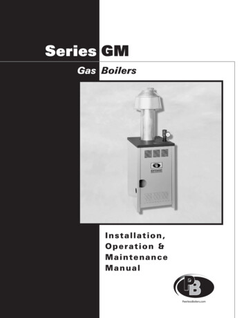
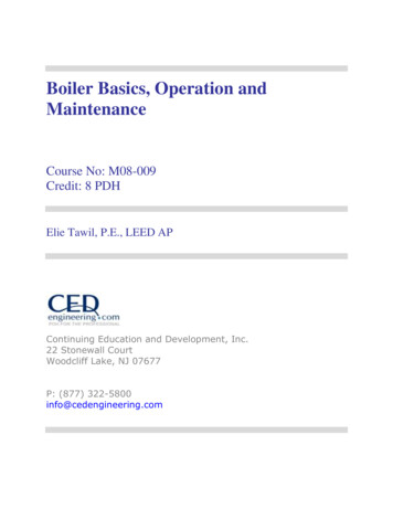
Cast Iron Condensing Boilers – Installation ManualFigure 1 - KN-Series Multiple Boiler Common VentingFLUE VENT"B"DOUBLE ACTINGBAROMETRIC DAMPERALL CONNECTIONSTO BE "T-WYE""C""D"THERMAL SPILLSWITCH"F"VERTICAL CHIMNEY VENTING - VERTMULTIPLE BOILER INSTALLATIONS.IT IS RECOMMENDED THAT THE BOWHEN THE HORIZONTAL DISTANCEWHEN SIZED FOR A (CAT II) CONFIGREQUIRED IN EACH BOILER'S RISERDAMPER MUST BE INSTALLED AS ILACCEPTED ENGINEERING PRACTICEBAROMETRIC DAMPERS, THE BAROCODES, INSTALL A THERMAL SPILL1. CONNECT EACH BOILER RISER TOONLY2. INSTALL AN APPROVED VENT CAP3. DIMENSIONS:B BREECHING LENGTHC CHIMNEY HEIGHTD BREECHING DIAMETERF RISER DIAMETER(NO SMALLER THAN THE DIMENSAIOM-051 FBOILER #4(IF REQUIRED)BOILER #3(IF REQUIRED)BOILER #2(IF REQUIRED)4. SIZE THE CHIMNEY AND BREECHIMANUFACTURER'S RECOMMENDENGINEERING PRACTICES. (CONSU100 FT.)BOILER #1MULTIPLE BOILER NEGATIVE DRAFT VENTING INSTALLATIONVERTICAL CHIMNEY VENTING - Vertical venting multiple boiler installations:It is recommended that the boiler nearest the verticalchimney be fired first when the horizontal distanceexceeds 50% of the vertical distance.When sized for a (CAT II) configuration, a negativepressure of 0.02 to 0.10 inches WC is required in eachboiler’s riser when all boilers are operating at full input.A barometric damper must be installed as illustrated.[Exception: if the vent system is designed using acceptedengineering practices, and the design calculations provethere is no need for barometric dampers, the barometricdampers may be omitted.] When required by applicablecodes, install a thermal spill switch on each barometricdamper.101. Connect each boiler riser to the common vent with aY connection only.2. Install an approved vent cap at each vent termination.3. Dimensions:B breeching lengthC chimney heightD breeching diameterF r iser diameter(No smaller than the dimension given in Table 4)4. Size the chimney and breeching per local codes andvent pipe manufacturer’s recommendations, usinggenerally accepted engineering practices. (Consultfactory for vertical heights beyond 100 ft.)
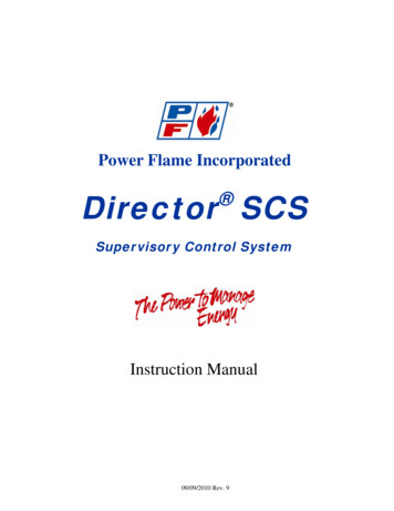
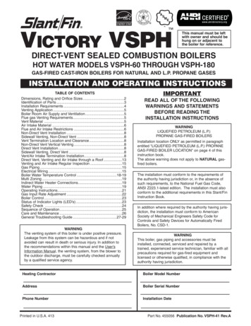
Cast Iron Condensing Boilers – Installation ManualFigure 2 - Horizontal Air Intake and Venting for a Single Direct Vent SystemPITCH PIPE DOWNTOWARDS BOILER1/4 IN/FT[20 mm/m]10 FT [3.1 m]MINIMUMTO ADJACENTBUILDINGREFER TO TABLE "Y"FOR APPROVED VENTTERMINATION ANDDIMENSIONAL DATAPITCH PIPE DOWNTOWARDS TERMINALCAP 1/4 IN/FT[20 mm/m]EXHAUST"X"MINIMUMBETWEEN TERMINALS@ CENTER LINE"Y" MINIMUMBETWEEN TERMINALSCOMBUSTION AIR1.5 FT [0.5 m] MINIMUM DISTANCE FROMINTAKE TO MAXIMUM SNOW LINE.NOTES:1. DIMENSIONS ARE IN INCHES (IN), FEET (FT), MILIMETERS [mm] ORMETERS [m] AS SHOWN.Figure 3 - Horizontal Air Intake and Venting for Multiple Direct Vent SystemsEXHAUST TERMINALBANKCOMBUSTION AIRINTAKE TERMINALBANK2 IN [50.8 mm] MINIMUMBETWEEN TERMINALS1.5 FT [0.5 m] MINIMUMDISTANCE FROMINTAKE TO MAXIMUMSNOW LINE.NOTES:AIOM-065 B1. DIMENSIONS ARE IN INCHES (IN), FEET (FT), MILIMETERS [mm] ORMETERS [m] AS SHOWN.11
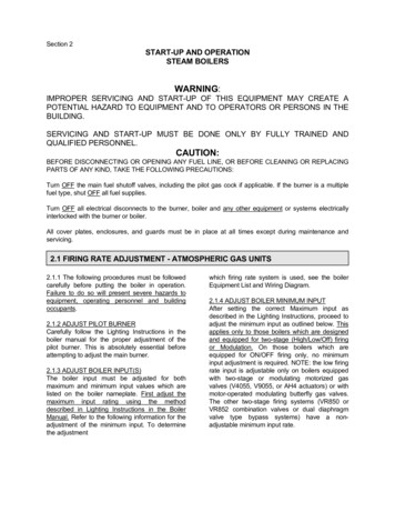
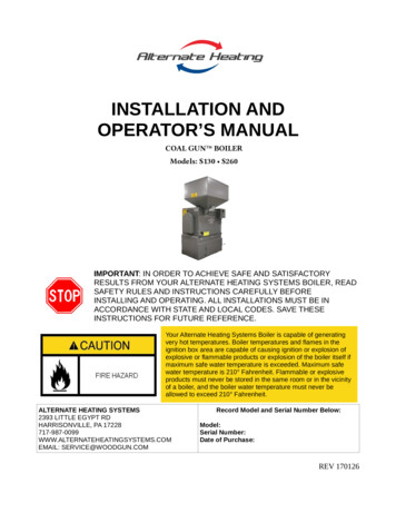
Cast Iron Condensing Boilers – Installation ManualFigure 4 - Vertical Air Intake and Venting for Direct Vent SystemAIOM-003 CFigure 5 - Combination Direct Vent SystemsMAXIMUMMINIMUMEXHAUSTCOMBUSTION AIRMAXIMUM12
Cast Iron Condensing Bo
operation and maintenance of a KN series boiler. long life for which this boiler was designed, these instructions must be read, understood and followed. The KN boiler series has been design certified by CSA for use with natural gas under the latest revision of ANSI-Z21.13/CSA 4.9, Gas-Fired Hot Water Boilers and