Transcription
SIGNATURE 2 SERIESSignature 2 SeriesSoftener ManualInstallation / Operation ManualFully Automatic & DemandWater Softeners
SIGNATURE 2 SERIESSoftener Specifications.Page 3Softener Installation.Page 5Softener Capacity.Page 10Installing the Control Valve.Page 13Control Start-Up Procedures.Page 15Master Programming.Page 18Utilizing Bluetooth.Page 20Control Valve Assembly.Page 21Valve Body Assembly.Page 22Valve Body Parts.Page 23Meter Assembly.Page 24Additional Information.Page 25Troubleshooting.Page 28Error Codes.Page 29
SIGNATURE 2 SERIESSoftener SpecificationsGeneralSpecificationsCabinetTwo TS128V-S2MS128V-S224,000 / 1220,250 / 7.515,000 / 4.532,000 / 1527,000 / 920,000 / 624,000 / 1220,250 / 7.515,000 / 4.532,000 / 1527,000 / 920,000 / 648,000 / 2440,500 / 1530,000 / 964,000 / 3054,000 / 1840,000 / 1296,000 / 4581,000 / 2760,000 / 18128,000 / 60108,000 / 3680,000 / 24Maximum Raw WaterHardness (grains)50755075100100100100Maximum Clear Iron /Manganese35355555Exchange Resin (cu ft pertank).751.0.751.01.52.03.04.0Mineral Tanks (polyglass)8 x 3510 x 358 x 449 x 4810 x 5412 x 5214 x 6516 x 65Brine Tank (polyethylene wgrid & safety)N/AN/A18 x 3318 x 3318 x 3318 x 3318 x 4024 x 50Service Flow Rate (gpm peractive tank)*8.011.08.010.011.012.014.016.0Backwash Flow Rate (gpm)1.52.41.52.02.43.54.05.0Gallons Used / Regeneration79987990101140164189Backwash Flow Rate (gpm)Vortech (V) Units1.22.01.21.52.02.43.540Gallons Used / RegenerationVortech (V) Units698869789011714816123x14x 4523x14x4518x26x5318x27x 5618x28x 6218x30x 6018x32x 7424 x 40 x 748810088100133164285378Grains Capacity Regeneration / Lbs Salt UsedSpace RequiredApproximate Shipping Weight(lbs)WARNINGLubricantsDo NOT use Vaseline, oils, hydrocarbon lubricants or spray silicone anywhere! Petroleum base lubricants willcause swelling of o-rings and seals. The use of other lubricants may attack plastic Noryl . It is recommended thatDow Corning silicone grease be used as a lubricant for all control valves. Dow Corning 7 Release Compoundis used in the manufacture of Chandler Systems control valves. (Part # LT-150)SealantsPipe dope and liquid thread sealers may contain a carrier that attacks some plastic materials. It is recommendedthat Teflon tape be used to seal plastic Noryl threaded fittings.3
SIGNATURE 2 SERIESSoftener SpecificationsPLEASE NOTE THESE SPECIFICATIONS BEFORE PROCEEDINGOPERATING PRESSURE RANGE : 20 - 125 PSIOPERATING TEMPERATURE RANGE : 33º F - 120º FINLET / OUTLET PIPE SIZE : 3/4: FNPTPLEASE COMPLY WITH ALL APPLICABLE PLUMBING CODESPROTECT THE SOFTENER AND PIPING FROM FREEZING TEMPERATURESPlease read the entire Owner’s Manual and Instruction before installation.This Owner’s Manual must stay with the unit.-How A Water Softener WorksWater hardness is derived from Calcium and Magnesium minerals that have been dissolved into the water underthe earth’s surface. These minerals are found in limestone deposits and are the source of hard water. The amountof hardness in a given water supply is dependent upon the quantity of Calcium and Magnesium present and thelength of time water has been in contact with them. This can vary dramatically from well-to-well and, for this reason,a water analysis is imperative in order to determine the proper treatment method. The degree of hardness increases as the concentration of Calcium and Magnesium “ions” increase and is measured in Grains Per Gallon (gpg).The problem of hard water in the home / business comes to light in many facets of daily use. Water spots and scumleft behind on bathtubs, fixtures and showers; wear and tear on appliances; calcium build-up in hot water heatersand piping; and, greater amounts of soap and detergents being used are just a few examples.The modern water softener is designed to reduce hardness ions and their unpleasant side effects. Special resinbeads in the softener mineral tank are used to change hard water into soft water. The surfaces of these beads arecovered with sodium ions. As hard water enters the mineral tank and comes into contact with the resin, an exchange of ions takes place as dissolved Calcium and Magnesium ions cling to the resin surface and sodium ionstake their place, thus softening the water. This process is called Ion Exchange. Over time, the sodium ions usedfor the exchange process become depleted and must be replenished.The water softener provides a Regeneration process whereby brine solution enters the mineral tank, driving-offthe collected hardness ions and replenishes the surface of the resin beads with more sodium ions. This process isautomatically initiated by the control valve on the mineral tank. The regeneration process has five basic cycles asfollows:1. Backwash - The control valve directs the water flow in a reverse direction through the mineral tank, separatingthe resin beads and flushing any accumulated particles to a waste drain.2. Brine & Rinse - In the first part of this cycle, the control valve directs brine solution downward through themineral tank, driving-off collected hardness ions and replenishing the resin beads with sodium ions. The secondpart of the cycle rinses hardness ions and excess brine from the mineral tank to the waste drain.3. Rapid Rinse - The control valve directs the water flow downward, settling and recompacting the resin bed.4. Brine Refill - The control valve directs fresh water into the salt compartment to create new brine solution for thenext scheduled regeneration.5. Service - This is the normal “operating” cycle where hard water enters the mineral tank, comes into contact withthe resin beads and exchanges hardness ions for sodium ions - the water then becomes “soft” and ready foruse.4
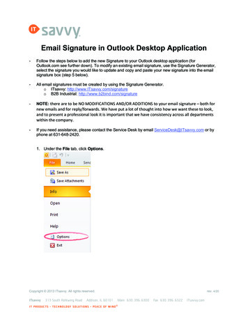
SIGNATURE 2 SERIESInstallation-Pre-Installation Check ListA water test should always be performed in order to determine total water hardness (in gpg) and total dissolved iron (in parts per million - ppm). This is critical for proper equipment selection, sizing and for determiningthe program for regeneration frequency. If heavy concentrations of iron (above 5 ppm), iron coloration, iron bacteria or sediment are present, filtration prior to the softener will most generally be required. Certain states mayrequire a licensed plumber for installation.Note : Flexible water supply connectors and flexible drain line tubing may not be allowed in you locale. Pleasecheck with local plumbing code officials prior to installation.Installation Requirements A level floor position ahead of piping into water heater. Unit must be installed at least 10’ ahead of the inlet to a water heater to prevent damage due toback-up of hot water. DO NOT install the unit in an area of direct sunlight or where freezing temperatures may occur!(See Installation Diagrams for proper placement and plumbing connections.) A level floor position ahead of piping into water heater. Unit must be installed at least 10’ ahead of the inlet to a water heater to prevent damage due toback-up of hot water. DO NOT install the unit in an area of direct sunlight or where freezing temperatures may occur!(See Installation Diagrams for proper placement and plumbing connections.)-Major System Components-1. Brine Tank - This tank holds the salt that is added to the softener. This salt is dissolved with water to form abrine solution used in the softener regeneration process.2. Resin Tank - This tank contains the ion exchange resin media. Water flows through the resin tank under pressure to come into contact with the resin for water softening.3. Control Valve - The valve directs water through the resin tank for water softening and controls the flow ofwater / brine for the regeneration process.5
SIGNATURE 2 SERIESInstallation-Softener Location / Other Requirements Locate the unit near an unswitched, 120 volt / 60 Hz grounded electrical outlet. Check for distance and proper drain installation (e.g. floor drain, washing machine standpipe). Determine type and size of piping required for softener connection (e.g. copper, galvanized, PVC plastic).Note If household plumbing is galvanized and you intend to make the installation with copper (or vise versa),obtain di-electric unions to prevent dissimilar metal corrosion. Where the drain line is elevated above the control valve or exceeds 20 feet in length to reach the drain,use 3/4" I.D. drain line tubing instead of 1/2" I.D. Drain line tubing is not included. All plumbing lines not requiring “soft” water should be connected “upstream” of the softener. The brine tank drain line is gravity flow and must discharge below the overflow fitting. The brine overflow is provided as a back-up in the event the safety float shut-off should fail, allowing the brinetank to overfill. This drain connection would then carry the excess water to the drain and prevent flooding ofthe floor. Therefore, no liability will or can be assumed by the manufacturer of the softener should this occur.Caution If sweat soldering copper pipe (remember to always use lead free solder and flux), cover yoke and bypassvalve with wet rags to prevent heat damage to connections and control valve! If using PVC or plastic pipeprimers and solvent cements specifically recommended for use with potable water are required. Do not “TEE” to the main drain line from control valve.6
SIGNATURE 2 SERIESInstallation-Installation Procedure- Water Supply Connections and Bypass Valve To allow for softener servicing, swimming pool filling or lawn sprinkling, a manual bypass valve has been installedat the factory. The bypass allows hard water to be manually routed around the softener.1. Position softener at desired location for installation. (See Installation Diagrams.)2. For TS96V, TS128V, MS96V & MS128V Units ONLY - The resin material is shipped separately from themineral tank. Remove the valve by unscrewing from center hole. Use a cork or tape to place over top of distributortube to prevent material from entering tube while filling. Place funnel in hole. Pour several gallons of water in thetank.No gravel is required. Pour in the resin material. Remove funnel and cork or tape from distributor tube. Clean tankthreads and fill the mineral tank completely with water. Replace the valve, being careful to position the distributortube into the distributor tube pilot hole.Note : If rebedding an existing unit and the system utilizes a standard tube & basket style distributor, a “D” gravelunderbedding will be required.3. Turn OFF main water supply and OPEN nearest faucet to relieve pressure.4. Cut main line and install appropriate elbows and extensions. Inlet and outlet connections on the control valve are3/4” FNPT. (1” FNPT for TS96V, MS96V, TS128V & MS128V units.)Caution : Raised arrows located on the sides of control valve body and bypass valve indicate proper direction of waterflow. Install inlet and outlet piping in direction of arrows.6. Rotate bypass valve to the bypass position (position of lever is at right angle to inlet / outlet piping).7. Turn the main supply line on to restore water service to the home.8. OPEN nearest faucet to evacuate air and repressurize plumbing lines.9. Check for leaks!-Drain Line Connection1. Pull out clip and remove drain line assembly located on the left side of control valve. Remove drain line hose barband wrap threads with Teflon tape. Reinstall drain line hose barb. Caution : Hand tighten only!!! Replace drain lineassembly and reinstall clip.2. Install 1/2” I.D. drain line tubing (not included) from hose barb to an open drain. A 4” gap between the end of thedrain line and the open drain is required to prevent waste water backflow. Keep the drain line as short as possible.An overhead drain line can be used if necessary, but should discharge below the control valve. A syphon trap(taped loop) at the outlet of the drain line is advisable to keep the drain line full and assure correct flow duringregeneration. Elbows or other fittings must be kept at a bare minimum.Note : Where the drain line is elevated above the control valve or exceeds 20’ in length, 3/4” I.D. drain line tubingshould be used.7
SIGNATURE 2 SERIESInstallation-Brine Line and Overflow Connection1. Position brine tank on a smooth, level surface near the softener resin tank. If necessary, the brine tank can beplaced at a higher level than the resin tank, but never at a lower level.2. Install one end of 3/8" O.D. by 1/4" I.D. brine line tubing (included with unit) to compression fitting located on left sideof control valve.3. Remove brine tank cover.4. Remove cap from brine well.5. Insert opposite end of brine line through outer hole in brine tank.6. Connect brine line to compression fitting on safety brine valve located inside brine well. Replace brine well cap.7. Install 1/2" I.D. drain line tubing (not included) to the overflow fitting on brine tank located just below the brine line.8. Run the opposite end of brine tank drain line to a suitable drain.- Electrical Connection 1.Connect the power cord and plug power supply into a 115 volt / 60 Hz receptacle.Note : Do not plug into an outlet controlled by a wall switch or pull chain that could inadvertently be turned offElectronic ConnectionsP Power SupplyB Powered in Backwash Cycle OnlyS Powered in Entire Regen. Cycle8
SIGNATURE 2 SERIESInstallation- Pressurizing The System 1. Make certain Signature Series Control Valve is in SERVICE position.2. Slowly rotate bypass valve to the SERVICE position. (Position of bypass lever is parallel to inlet / outlet piping.)3. Open the nearest faucet to evacuate air from plumbing lines.4. Check for leaks! If water is observed leaking from bottom of bypass, close and open bypass lever several times toseat o-rings.5. After air is evacuated from plumbing lines, close bypass (position of bypass lever is perpendicular to the direction ofinlet pipe) on bypass valve.- Programming The Control Valve For “TS” Units 1.2.3.4.Set time of day.Set a.m. or p.m.Set number of days between regeneration. (Refer to Regeneration Charts below.)Follow along the line indicating the number of persons in the family to the column that corresponds with the hardnessrange. This will indicate how many days between regeneration should be programmed. (Refer to Figure 1.)Note :Salt settings are pre-set at the factory for the maximum shown on the capacity charts.Warning : Do not reduce salt settings below 9 lbs. as the water level in the brine tank will not reach the grid plate.- How To Use The Capacity Charts -EXAMPLEHARDNESS 20 gpg20 gpgUNIT SELECTED32,000 GRAINIRON 3 ppm X 412 gpgNUMBER OF PERSONS4MANGANESE 1 ppm X 44 gpgCOMPENSATED HARDNESS36 gpgTOTAL COMPENSATED HARDNESS36 gpg9
SIGNATURE 2 SERIESCapacityFigure 19# cu. ft. salt settingModelCapacity 27,000 grainsNominal 32,000 Grain Units (-32)# of People12Hardness Range3456789Regeneration Frequency (# Days)3 - 10292114108765411 - 202110754332221 - 30147432221131 - 40105322111141 - 5084221111-51 - 607321111--61 - 7552111----Example : The regeneration frequency should be programmed for every two (2) days.Note :If the water contains iron and / or manganese, increase regeneration frequency to a minimum of every 12 daysto assure adequate cleaning of the resin. Use of resin cleaners or iron inhibiting salt is encouraged.ModelTS24-S2 & TS24V Models - Capacity 20,250 Grains# of People12Hardness Range356789Regeneration Frequency (# Days)3 - 102612864432211 - 20136422111-21 - 3094211----31 - 406211-----41 - 50421------Note : All charts assume 75 gallons per person per day usage.104
SIGNATURE 2 SERIESCapacityModelTS32-S2 & TS32V Models - Capacity 27,000 Grains# of People12Hardness Range3456789Regeneration Frequency (# Days)3 - 1029171186644311 - 20178643221121 - 30115321111131 - 40842111---41 - 506311-----51 - 605211-----61 - 75411------ModelTS48-S2 & TS48V Models - Capacity 40,500 Grains# of People12Hardness Range3456789Regeneration Frequency (# Days)3 - 202613864432221 - 30178543221131 - 40126422111-41 - 5010432111--51 - 6084211----61 - 70732111---71 - 806211-----81 - 90521------91 - 100421------ModelTS64-S2 & TS64V Models - Capacity 54,000 Grains# of People12Hardness Range3456789Regeneration Frequency (# Days)3 - 2029171186544321 - 302311754322131 - 40178543221141 - 50136432111151 - 60115321111-61 - 70942211---71 - 80842111---81 - 9073111----91 - 1006311----11
SIGNATURE 2 SERIESCapacityModelTS96V Models - Capacity 81,000 Grains# of People123Hardness Range456789Regeneration Frequency (# Days)3 - 202927171310876521 - 3029171186544331 - 402713864432241 - 502110643322151 - 60178543321161 - 70147432211171 - 80136422111181 - 90115321111-91 - 1001043211---89ModelTS128V Model - Capacity 108,000 Grains# of People12Hardness Range34567Regeneration Frequency (# Days)3 - 2029292317131198721 - 30292315119765431 - 4029171186544341 - 502813965433251 - 602311754322261 - 70209643222171 - 80178543221181 - 90157432211191 - 1001364321111- Programming The Control Valve For “MS” Units 1. Set time of day.2. Set a.m. or p.m.3. Set water hardness in grains per gallon (gpg).Note : If the water contains iron and / or manganese, multiply the total parts per million (ppm) by “four” (4) and then add tothe grains per gallon (gpg) of hardness. Use this COMPENSATED HARDNESS level when programming the regenerationfrequency.1. Set regeneration day override if other than (7) days is desired. (This is particularly useful when iron is being treated toprevent fouling of the resin.)2. Set regeneration time, if other than 2:00 a.m. is desired.12
SIGNATURE 2 SERIESInstallationNote : Salt settings are pre-set at the factory for the maximum shown on the capacity charts.Warning :Do not reduce salt settings below 9 lbs. as the water level in the brine tank will not reach the grid plate.- Control Valve Operation 1. Advance control valve to BACKWASH (cycle 1) position and allow water to run to drain for 3 to 4 minutes.Warning : Close valve on bypass prior to selecting the backwash position. After backwash position has beenestablished, slightly open bypass to evacuate air from the media tank. Fully open valve when all airis depleted. This procedure will prevent media from being uplifted into control valve.2. Advance control valve to BRINE REFILL (cycle 4) position and allow the brine tank to fill just over the salt grid plate.3. Advance control valve to BRINE & RINSE (cycle 2) and allow the control valve to draw water from the brine tank until itstops. If no draw is observed, check tightness of brine line compression fittings.4. Advance control valve to RAPID RINSE (cycle 3) position and let run to drain for 3 - 4 minutes.5. Advance control valve to BRINE TANK REFILL (cycle 4) position and allow the control valve to automatically fill thebrine tank.Note : Control valve will advance to service position automatically.- Start Up Procedure - Disinfection For disinfection of your unit, please follow the Sani-System Procedure on the back of the packet provided.- Filling The Brine Tank With Salt To expect a high level of performance and reliability, a salt manufactured specifically for water softeners must be used.Salt of this grade is virtually free from dirt and other particulates that would eventually cause the softener to malfunction.A pellet type salt is recommended, although any high quality water softener salt (such as solar salt) will suffice. If iron ispresent in raw water, use of iron inhibiting salt is recommended. The salt level will decrease after each regeneration cycle.Consequently, the salt compartment will need to be checked and replenished periodically.1. Fill the brine tank or salt compartment with water softener salt as described above. This will be approximately 250pounds of salt. (150 lbs. for cabinet models.)Warning : Do not fill salt above level of the brine well.2. Replace brine tank lid.13
SIGNATURE 2 SERIESInstallation- Final Check 1. Be certain the bypass valve is in the SERVICE position.2. Make sure the power supply is connected to an uninterrupted 115-volt outlet.3. Check that the time of day is set4. Double check regeneration schedule.5. Make final check for leaks!6. Fill out warranty card online at www.csiwater.com7. Leave all manuals with unit.- Operation, Care and Cleaning When the bypass valve is in the SERVICE position (position of bypass lever is parallel to the inlet / outlet piping), wateris directed through the water softener. Water may be bypassed by turning the lever to the bypass position (position ofbypass lever is at right angles to inlet / outlet piping). Water to the home will bypass the softener and be untreated.You should manually bypass the softener if :1. The outside lines do not bypass the water softener and water is to be used for lawn sprinkling or other similar uses.2. Servicing the water softener.3. A water leak from the water softener is evident.4. Shock treating water well and piping with chlorine or other disinfectant.- Extra Regeneration If soft water demands are unusually heavy, an extra regeneration can be initiated manually :- To Skip A Regeneration 1. For vacations or extended periods of absence, the power supply can be disconnected from the control valve. It isrecommended that the 9-volt battery be removed.2. Upon return, plug in cord and reset the time of day. Replace 9-volt battery.- General Care and Cleaning 1. Do not place heavy or sharp objects on water softener or cabinet.2. Use only mild soap and warm water to clean exterior of the unit. Never use harsh, abrasive cleaners.3. Protect the water softener and drain line from freezing.4. Reset time for daylight saving time periods.5. Replace 9-volt battery once a year.6. Inspect and clean the brine tank when sediment appears in the bottom of the salt compartment.7. Always keep the brine tank supplied with good quality salt, a type designed for use in water softeners.14
SIGNATURE 2 SERIESControl Start-Up Procedures- Programming The Control Valve For “TS” Units 1.2.3.4.Set time of day.Set a.m. or p.m.Set number of days between regeneration. (Refer to Regeneration Charts below.)Follow along the line indicating the number of persons in the family to the column that corresponds with the hardnessrange. This will indicate how many days between regeneration should be programmed. (Refer to Figure 1.)Note :Salt settings are pre-set at the factory for the maximum shown on the capacity charts.Warning : Do not reduce salt settings below 9 lbs. as the water level in the brine tank will not reach the grid plate.Main Menu12:001.To enter Main Menu, press the Menu/Enter button.(Time of Day will flash)2.To set the Time of Day, press the Set/Change button.(First digit will flash) Example [12-00]To change digit value, press the Set/Change button.To accept the digit value, press the Menu/Enter button.Next digit will flash to begin setting.Once the last digit display is accepted, all digits will flash.3.To set A.M. or P.M., press the Menu/Enter button.To change digit value, press the Set/Change button.To accept the digit value, press the Menu/Enter button.Once A.M. or P.M. is accepted, the next menu item will flash.Example [A]a. To set the Number of Days between Regeneration (A), press the Set/Change button.(Time Clock Softeners)Repeat instructions from step (2).Example [ A - 07 ]Notes: 1) Maximum value is 29.2) If value set to 0, Regeneration will never occur.3) Default setting is 4 days for softeners.b. To set Hardness (Metered Softeners Only) an “H” will appear to enter CompensatedHardness in grains per gallon (gpg) Default setting is 25 gpg. Example [ H - 25]4.5.To Exit Main Menu, press the Menu/Enter button.Note: If no buttons are pressed for 60 seconds, the Main Menu will be exited automatically.15
SIGNATURE 2 SERIESControl Start-Up ProceduresNormal Operation1. Home Displaya. Time Clock Softeners -Alternates between the display of Time of Day and Number ofDays until the Next Regeneration.- Days Remaining until the Next Regeneration will count down from the enteredvalue until it reaches 1 day remaining.- A Regeneration Cycle will then be initiated at the next designated regenerationtime.b. Metered models alternate the Time of Day and Gallons left until the nextregeneration. The meter will count down to zero (0000) and then regenerate at thescheduled time set.2. Battery Back-Up (Uses a standard 9-volt alkaline battery.)Features of Battery Back-Up: During power failures, the battery will maintain the time of day as long as thebattery has power. The display is turned off to conserve battery power duringthis time. To confirm that the battery is working, press either button and thedisplay will turn on for five (5) seconds. If power failure occurs while system is regenerating, the Signature Series 2will motor to a shut off position to prevent constant flow to drain. Dependingupon system pressure and other factors, it is possible to observe a reduced flow todrain during this step. After power is restored, the Signature Series 2 will returnand finish the cycle where it left off prior to the power interruption. When used without battery back-up, during a power failure, the unit stops at itscurrent point in the regeneration position and then restarts at that point when thepower is restored. The time will be offset by the increment of time the unit waswithout power, so it is necessary to reset the time of day on the unit. No othersystem will be affected.16
SIGNATURE 2 SERIESControl Start-Up ProceduresStarting Extra Regeneration CycleTo Start Delayed Extra Cycle Example [ 1 ]If Days Remaining Until Next Regeneration does not read ‘1’, press and hold theSet/Change button for 3 seconds until the display reads ‘1’, or ‘0000’ on meteredmodels.Regeneration cycle will initiate at the next designated regeneration time.1.2.To start Immediate Extra CycleFirst complete above step.With Days Remaining Until Next Regeneration at ‘1’ or ‘0000’,Press and hold the Set/Change button.After 3 seconds, the regeneration cycle will begin.3.To Fast Cycle thru regenerationFirst complete above 2 steps.Note: Press and hold the Set/Change button for 3 seconds to advance to the next cycle step.Fast Cycle is not necessary unless desired to manually step through each cycle step.(Repeat until valve returns to the home display)SoftenersStep 1Step 2Step 3Step 4Default (Min)BackwashBrine & RinseRapid RinseBrine Refill1060109 lbs/ cu ft17
SIGNATURE 2 SERIESMaster Programming ModeMaster Programming ModeTo enter Master Programming Mode, press and hold both buttons for 5 seconds.Note: All Master Programming functions have been preset at the factory. Unless a change is desired,it is NOT necessary to enter Master Programming Mode.1. Regeneration Time ( r )Example [ r 2A ]- The time of day at which regeneration may take place is designated by the letter “r”.- Default regeneration time setting for SOFTENERS is 2a- The first display digit indicates A.M. or P.M. To change the value, press the Set/Change button.- Press Menu/Enter button to accept the value and move to the next digit.- The second and third display digits indicate the hour at which the regeneration will occur.- Change the digits with the Set/Change button and accept with the Menu/Enter button.- After the entire display flashes, press the Menu/Enter button to move to the next menu item.2. Regeneration Day Override (A) – Meter (Demand) Mode Only- Press Menu/Enter button. This display is used to set the maximum amount of time (in days)the unit can be in service without regeneration. This setting is identified by theletter “A” in the left digit. Regeneration will begin at the scheduled time. A setting of zerowill cancel this feature.- Example: Override every 7 days (A-07), default setting, or cancel setting (A-00). Maximum is 29.3. Regeneration Cycle Step Times (Steps 1, 2, 3, 4)Example [ 3 - 10 ]- The next 4 displays set the duration of time in minutes for each regeneration cycle step.- The step number which is currently modifiable is indicated on the far left of the displayscreen.- The number of minutes allotted for the selected backwash step is displayed on the farright.- Change the digit values using the Set/Change and Menu/Enter buttons as describedabove.4. System Capacity in Grains ( c ) – Meter (Demand Mode Only)- Press the Menu/Enter button. This display is used to set the system capacity in grainsand is used in conjunction with the hardness setting to calculate total gallons of treat
SIGNATURE 2 SERIES -Installation Procedure-- Water Supply Connections and Bypass Valve - To allow for softener servicing, swimming pool filling or lawn sprinkling, a manual bypass valve has been installed at the factory. The bypass allows hard water to be manually routed around the softener. 1. Position softener at desired location for .