Transcription
PRACTICAL ELECTRONICSHANDBOOK
This page intentionally left blank
PRACTICAL ELECTRONICSHANDBOOKSIXTH EDITIONIAN R. SINCLAIR AND JOHN DUNTONAMSTERDAM BOSTON HEIDELBERG LONDON NEW YORKOXFORD PARIS SAN DIEGO SAN FRANCISCOSINGAPORE SYDNEY TOKYONewnes is an imprint of Elsevier
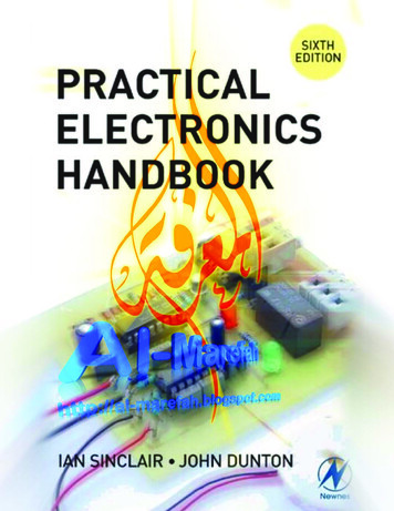
Newnes is an imprint of ElsevierLinacre House, Jordan Hill, Oxford, OX2 8DP30 Corporate Drive, Burlington, MA 01803First edition 1980Reprinted 1982, 1983 (with revisions), 1987Second edition 1988Reprinted 1990Third edition 1992Fourth edition 1994Reprinted 1997, 1998, 1999Fifth edition 2000Reprinted 2001Sixth edition 2007Copyright 1980, 1988, 1992, 1994, 2000, 2007, Ian R. Sinclair and John Dunton. Published by Elsevier Ltd.All rights reservedThe right of Ian R. Sinclair and John Dunton to be identified as the author of this work has been asserted inaccordance with the Copyright, Designs and Patents Act 1988No part of this publication may be reproduced, stored in a retrieval system or transmitted in any form or byany means electronic, mechanical, photocopying, recording or otherwise without the prior written permission ofthe publisherPermission may be sought directly from Elsevier’s Science & Technology Rights Department in Oxford,UK: phone ( 44) (0) 1865 843830; fax ( 44) (0) 1865 853333; email: permissions@elsevier.com. Alternativelyyou can submit your request online by visiting the Elsevier web site at http://elsevier.com/locate/permissions,and selecting Obtaining permission to use Elsevier materialNoticeNo responsibility is assumed by the publisher for any injury and/or damage to persons or property as a matter ofproducts liability, negligence or otherwise, or from any use or operation of any methods, products, instructionsor ideas contained in the material herein. Because of rapid advances in the medical sciences, in particular,independent verification of diagnoses and drug dosages should be madeBritish Library Cataloguing in Publication DataA catalogue record for this book is available from the British LibraryLibrary of Congress Cataloging-in-Publication DataA catalog record for this book is available from the Library of CongressCover photo by Thomas Scarborough, reproduced by permission of Everyday Practical Electronics. www.epemag.co.ukISBN 13: 978-0-75-068071-4ISBN 10: 0-75-068071-7For information on all Newnes publications visit our web site at books.elsevier.comTypeset by Cepha LtdPrinted and bound in Great Britain07 08 09 10 1110 9 8 7 6 5 4 3 2 1
vContentsCONTENTSPrefaceIntroduction: Mathematical ConventionsxiiixvResistors1CHAPTER 1Passive componentsResistorsResistivityResistivity calculationsResistor constructionTolerances and E-seriesResistance value codingSurface mounted resistorsResistor characteristicsDissipation and temperature riseVariables and lawsResistors in circuitKirchoff’s lawsThe superposition theoremThevenin’s theoremThermistorsVariation of resistance with temperatureCHAPTER 2CapacitorsCapacitanceThe parallel-plate capacitorConstructionOther capacitor characteristicsEnergy and charge storageTime constantsReactanceCR circuitsCHAPTER uctive and Tuned Circuit ComponentsInductorsTransformers474751
viContentsSignal-matching transformersMains transformersOther transformer typesSurface-mounted inductorsInductance calculationsUntuned transformersInductive reactanceLCR circuitsCoupled tuned circuitsQuartz crystalsTemperature effectsWave filtersCHAPTER 4Chemical Cells and BatteriesIntroductionPrimary and secondary cellsBattery connectionsSimple cellThe Leclanché cellThe alkaline primary cellsMiniature (button) cellsLithium cellsSecondary cellsNickel–cadmium cellsLithium-ion rechargeable cellsCHAPTER 7Active Discrete ComponentsDiodesVaractor diodesSchottky diodesLEDsPhotodiodesTransient voltage suppressors (TVS)Typical diode circuitsTransistorsBias for linear amplifiersTransistor parameters and linearamplifier gainTransistor packagingNoiseVoltage gain111111115116116117120122122128132136137137
ContentsOther bipolar transistor typesDarlington pair circuitField-effect transistorsFET handling problemsNegative feedbackHeatsinksSwitching circuitsOther switching devicesDiode and transistor codingCHAPTER 6138139139143144148150154160Linear ICsOverviewThe 741 op-ampGain and bandwidthOffsetBias methodsBasic circuitsGeneral notes on op-amp circuitsModern op-ampsOther operational amplifier circuitsCurrent differencing amplifiersOther linear amplifier ICsPhase-locked loopsWaveform generatorsActive and switched capacitor filtersVoltage regulator ICsAdjustable regulator circuitsThe 555 timerCHAPTER 89191193Familiar Linear CircuitsOverviewDiscrete transistor circuitsAudio circuitsSimple active filtersCircuits for audio output stagesClass D amplifiersWideband voltage amplification circuitsSine wave and other oscillator circuitsOther crystal oscillatorsAstable, monostable and bistable circuitsRadio-frequency circuitsModulation circuits197197197202204207211214216217223226230
viiiContentsOptical circuitsLinear power supply circuitsSwitch-mode power suppliesCHAPTER 8Sensors and TransducersIntroductionStrain and pressureDirection and motionLight, UV and IR radiationTemperatureSoundCHAPTER mable DevicesMemoryRead-only memory (ROM)Programmable read-only memory (PROM)Volatile memory (RAM)Programmable logicComplex programmable logicdevices (CPLD)Field programmable gate array (FPGA)Hardware description language (HDL)Other programmable devicesOther applications of memory devicesUseful websitesCHAPTER 11243Digital LogicIntroductionLogic familiesOther logic familiesCombinational logicNumber basesSequential logicCounters and dividersCHAPTER roprocessors and MicrocontrollersIntroductionBinary stored program computersVon Neumann and Harvard architectureMicroprocessor systemsPower-up reset and program execution307307308311314317
ContentsProgrammingThe ARM processorDeveloping microprocessor hardwareElectromagnetic compatibilityMicrocontroller manufacturersCHAPTER 12327327327327332338338Data ConvertersIntroductionDigital-to-analogue converters (DACs)Digital potentiometerBinary weighted resistor converterThe R2R ladderCharge distribution DACPulse width modulatorReconstruction filterAnalogue-to-digital convertersResolution and quantizationSamplingAliasingSuccessive approximationanalogue-to-digital converterSigma–delta ADC (over samplingor bitstream converter)Dual-slope ADCVoltage references for analogue-to-digitalconvertersPCB layoutConnecting a serial ADC to a PCUseful websitesCHAPTER 14318320322325325Microprocessor InterfacingOutput circuitsDisplay devicesLight-emitting diode (LED) displaysLiquid crystal displays (LCDs)Input circuitsSwitchesCHAPTER 61362363363367Transferring Digital DataIntroductionParallel transferIEEE 1284 Centronics printer interface369369370371
xContentsThe IEEE-488 busSerial transferEIA/TIA 232E serial interfaceRS-422/RS-485Wireless linksInfra-redAudio frequency signallingBase-band signallingError detection and correctionUseful websitesCHAPTER 15Microcontroller ApplicationsIntroductionConfigurationClockInternal RC oscillatorWatchdog and sleepPower-up resetSetting up I/O portsIntegrated peripheralsCounter timerPulse width modulatorSerial interfacesUART/USARTSPI/I2 C BusInterruptsImplementing serial output in softwareConverting binary data to ASCII hexUseful websitesCHAPTER 405407410410411412412413419420422424Digital Signal ProcessingIntroductionLow-pass and high-pass filtersFinite impulse response (FIR) filtersQuantizationSaturated arithmeticTruncationBandpass and notch filtersInfinite impulse response (IIR) filtersOther applicationsDesign toolsFurther reading425425426431432432433434434436437438
ContentsCHAPTER 17Computer Aids to Circuit DesignIntroductionSchematic captureLibrariesConnectionsNet namesVirtual wiringNet listsPrintingSimulationAnalysisDC AnalysisTemperature sweepAC AnalysisTransient analysisPCB layoutDesign rulesGerber and NC drill file checkingDesktop routing machinesUseful websitesCHAPTER 472477477479Connectors, Prototyping and Mechanical ConstructionHardwareVideo connectorsAudio connectorsControl knobs and switchesSwitchesCabinets and casesHandlingHeat dissipationConstructing circuitsSoldering and unsolderingDesolderingOther soldering toolsCHAPTER 19xi481481486487492493496497500501508512514Testing and TroubleshootingIntroductionTest equipmentTest leadsPower supplies and battery packsDigital multimetersLCR meter517517517517518519522
xiiContentsOscilloscopeSignal generatorTemperature testingMains workTestingFurther readingAppendix AAppendix BAppendix CAppendix DAppendix EAppendix FIndexStandard Metric Wire TableArithmatic and Logic Instructions TableHex record formatsGerber data formatPinout information linksSMT packages and guides522526527527529530531533537543553555557
PrefacexiiiPrefaceComponent data books are often little more than collections of specifications with little or nothing in the way of explanation or application and,in many cases, with so much information crammed into a small space thatthe user has difficulty in selecting what is needed. The cost of publishingpaper data books, the rate that new products are being brought to marketand the ease with which electronic copies of data sheets can be distributedby e-mail or downloaded from websites has begun to deter manufacturersfrom printing data books at all. This book, now in its sixth edition, hasbeen extensively revised, with a large amount of new material added, toserve the needs of both the professional and the enthusiast. It combinesdata and explanations in a way that is not served by websites.Although the book is not intended as a form of beginners’ guide to thewhole of electronics, the beginner will find much of interest in the earlychapters as a compact reminder of electronic principles and circuits. Theconstructor of electronic circuits and the service engineer should both findthe data in this book of considerable assistance, and the professional designengineer will also find that the items brought together here include manythat will be frequently useful and which would normally be available incollected form in much larger volumes.The book has been designed to include within a reasonable space mostof the information that is useful in day-to-day electronics together withbrief explanations which are intended to serve as reminders rather thanfull descriptions. In addition, topics that go well beyond the scope ofsimple practical electronics have been included so that the reader has accessto information on the advanced technology that permeates so much ofmodern electronics.IAN R. SINCLAIRJOHN DUNTON
This page intentionally left blank
IntroductionxvINTRODUCTION:MATHEMATICS CONVENTIONSQuantities greater than 100 or less than 0.01 are usually expressed in thestandard form of A 10n , where A is a number, called the mantissa,less than 10, and n is a whole number called the exponent. A positivevalue of n means that the number is greater than unity, a negative valueof n means that the number is less than unity. To convert a number intostandard form, shift the decimal place until the portion on the left-handside of the decimal point is between 1 and 10, and count the number ofplaces that the point has been moved. This is the value of n. If the decimalpoint has had to be shifted to the left the sign of n is positive; if the decimalpoint had to be shifted to the right the sign of n is negative.Example: 1200 is 1.2 103 and 0.0012 is 1.2 10 3To convert numbers back from standard form, shift the decimal pointn figures to the right if n is positive or to the left if n is negative.Example: 5.6 10 4 0.00056 and 6.8 105 680 000Note in these examples that a space has been used instead of the morefamiliar comma for separating groups of three digits (thousands and thousandths). This is recommended engineering practice and avoids confusioncaused by the use, in other languages, of a comma as a decimal point.Numbers in standard form can be entered into a calculator by using thekey marked Exp or EE – for details see the manufacturer’s instructions.Where formulae are to be worked out, numbers in standard form canbe used, but for writing component values it is more convenient to usethe prefixes shown in the table below. The prefixes have been chosen sothat values can be written without using small fractions or large numbers.
xviIntroductionSome variants of standard form follow a similar pattern in allowing numbersbetween 1 and 999 to be used as the whole-number part of the expression,so that numbers such as 147 10 4 are used. A less common conventionis to use a fraction between 0.1 and 1 as a mantissa, such as 0.147 107 .Powers of 10 and nopicoGMkmmnpPower of tenMultiplier1 000 000 0001 000 00010001/(1000)1/(1 000 000)1/(1 000 000 000)1/(1 000 000 000 000)Note that 1000 pF 1 nF; 1000 nF 1mF and so on. In computing, theK symbol means 1024 rather than 1000 and M means 1 048 576– thesequantities are the nearest exact powers of two.Examples: 1 kW 1000 W (sometimes written as 1 K0, see pages 7-8)1 nF 0.001 mF,1000 pF or 10 9 F4.5 MHz 4500 kHz 4.5 106 HzThroughout this book equations have been printed in as many forms asare normally needed so that the reader should not have to transpose theequations. For example, Ohm’s law is given in all three familiar forms ofV IR, R V/I and I V/R. The units that must be used with suchformulae are shown and must be adhered to – if no units are quoted thenfundamental units (amp, ohm, volt) are implied.For e
Digital multimeters 519 LCR meter 522. xii Contents Oscilloscope 522 Signal generator 526 Temperature testing 527 Mains work 527 Testing 529 Further reading 530 File Size: 8MBPage Count: 589
