Transcription
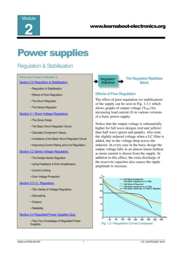
Module11AC TheoryTransformersWhat you’ll learn in Module 11. Section 11.1 Transformer Operation. Transformer Operation. Transformer Losses. Off Load Current.Introduction Volts per Turn. Transformers have been an essential component in electricaland electronic circuits since the 1830s and although newtechnologies in some electronic circuits have reduced theneed for transformers, they are still essential in manyapplications.Section 11.2 Magnetic Circuits &Transformer Cores. Magnetic Circuits & Cores. Magnetic Flux.How Transformers work. Reluctance.This module describes how transformers work, and how thedesign of both the transformer coils, and the core on whichthey are wound affects the efficiency of the transformer.Detailed descriptions of many types of transformer are alsogiven together with typical applications. Permeability. Common Core Types. Section 11.3 Power Transformers. Tappings.Isolation Toroidal Power Transformers. Switch Mode Power Supply Transformers.Transformers can allow separate circuits to be physicallyisolated from each other whilst still allowing current andvoltage to pass between the two. They can also be used toreduce or increase the voltage or current that is passed asrequired. Transformer Faults.Impedance Matching Isolation. Autotransformers. Section 11.4 Audio Transformers. 100V Line Transformers.Another common use for transformers can be to match inputand output impedances where the output of one circuit needsto pass an AC signal to the input of another. The advantageof this technique is that the transfer can be achieved withpractically no loss of power in the transfer. Data/Pulse Transformers.Transformers of many types. Transformers are made in a very wide range of sizes andconfigurations, from the enormous power transformers,weighing many tons that connect the different parts of thepublic electricity grid together, to tiny transformersconsisting of nothing more than a few turns of wire, found inUHF radio equipment. AF Transformers. Microphone Transformers.Section 11.5 Radio frequencyTransformers. RF Transformers. VHF Transformers. UHF Transformers. Screening. Section 11.6 Transformers Quiz.AC THEORY MODULE 10.PDF1 E. COATES 2007 -2010
www.learnabout-electronics.orgTransformersModule 11.1 Transformer BasicsWhat you’ll learn. After studying this section, you should be able to describe: Basic transformer operation Turns ratio. Power ratio. Transformation ratio. Transformer losses: Copper, Hysteresis & Eddy current. Transformer efficiency and off load current.Transformers.A transformer uses the principles of electromagnetism to change one A.C. voltage level to another.Faraday's work in the 19th century showed that a changing current in a conductor (e.g. atransformer primary winding) sets up a changing magnetic field around the conductor. If anotherconductor (secondary winding) is placed within this changing magnetic field a voltage will beinduced into that winding.Turns Ratio.Faraday also calculated that the voltage induced into the secondary winding would have amagnitude that depends on the TURNS RATIO of the transformer. i.e. If the secondary winding hashalf the number of turns of the primary winding, then the secondary voltage will be half the voltageacross the primary winding. Likewise, if the secondary winding has twice the number of turns of theprimary winding, the secondary voltage will be double the primary voltage.Power ratio.Because the transformer is a passive component, (it has no external power supply) it cannot producemore power out from its secondary than is applied to its primary. Therefore if the secondary voltageis greater than the primary voltage by a particular amount, the secondary current will be smallerthan the primary current by a similar amount, i.e. If the voltage is doubled the current will behalved.AC THEORY MODULE 11.PDF2 E. COATES 2007 -2011
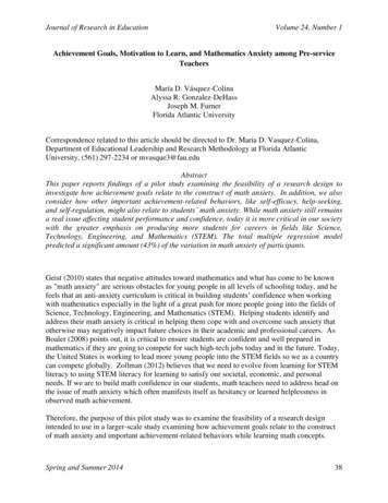
mation Ratio.Basic Transformer operation can be described by two formulae relating the transformation ratio tothe turns ratio of the transformer windings. VP the primary voltage. IP the primary current. VS the secondary voltage. IS the secondary current. NP the number of turns in theprimary winding. NS the number of turns in thesecondary winding.Transformer Losses.The formulae in Fig. 11.1.1 relate toan ideal transformer, i.e. atransformer with no power losses, inwhich, Primary volt amperes Secondary volt amperes.While practical transformers can beextremely efficient, some losses willFig 11.1.1 Basic Transformer Operation.occur because not all of the magneticflux produced by the primary windingwill link with the secondary winding. The power losses that occur in a transformer are of threetypes:1. Copper Losses.These losses can also be called winding losses or I2R losses, because they can occur in windingsmade from metals other than copper. The losses become evident as heat, generated in the (copper)wire windings as they dissipate power due to the resistance of the wire.The power loss in a transformer winding can be calculated by using the current in the winding andits resistance, in formula for power, P I2R. This formula is the reason copper losses are sometimescalled I2R losses. To minimise the losses the resistance of the winding must be kept low, using wireof suitable cross sectional area and low resistivity.2. Hysteresis losses.Each time the alternating current reverses (once each cycle), tiny "magnetic domains" within thecore material are reversed. These are physical changes within the core material and take up someenergy. The amount of energy used depends on the "reluctance" of the core material; in large coresof power transformers where hysteresis loss maybe a problem it is largely overcome by usingspecial low reluctance "grain oriented" steel as the core material.AC THEORY MODULE 11.PDF3 E. COATES 2007 -2011
www.learnabout-electronics.orgTransformers3. Eddy Current losses.Because the iron or steel core is an electrical conductor as well as a magnetic circuit, the changingcurrent in the primary will tend to set up an EMF within the core as well as in the secondarywinding. The currents induced into the core will oppose the changes of magnetic field taking placein the core. For this reason these eddy currents must be kept as small as possible. This is achievedby dividing the metal core into thin sheets or "laminations", each one insulated from the others byan insulating coat of lacquer or oxide. Laminated cores greatly reduce the formation of eddycurrents without affecting the magnetic properties of the core.In high frequency transformers eddy current losses are reduced by using a core made of a ceramicmaterial containing a large proportion of tiny metal particles, iron dust or manganese zinc. Theceramic insulates the metal particles from each other, giving a similar effect to laminations, andperforming better at high frequencies.Due to the ways of reducing losses described above, practical transformers closely approach theideal in performance. In large power transformers, efficiencies of about 98% can be achieved.Therefore for most practical calculations, it can be assumed that a transformer is "Ideal" unless itslosses are specified. The actual secondary voltages in a practical transformer will be only slightlyless than those calculated using the theoretical transformation ratio.Off Load Current.Because the action of a transformer is nearly perfect, the power in both primary and secondarywindings is the same, so when no load is put on the secondary, no secondary current flows and thepower in the secondary is zero (V x I 0). Therefore, although a voltage is applied to the primaryno current will flow, as the power in the primary must also be zero. In practical transformers the"Off Load Current" in the primary is actually very low.Volts per Turn.A transformer with a primary winding of 1000 turns and a secondary winding of 100 turns has aturns ratio of 1000:100 or 10:1. Therefore 100 volts applied to the primary will produce a secondaryvoltage of 10 volts.Another way to consider transformer voltages is by volts/turn; if the 100 volts applied to the 1000turn primary produces 100/1000 0.1 volts per turn, then each single turn on the 100 turnsecondary winding will produce 0.1V so the total secondary voltage will be 100 0.1V 10V.AC THEORY MODULE 11.PDF4 E. COATES 2007 -2011
www.learnabout-electronics.orgTransformersModule 11.2 Magnetic Circuits and Transformer Cores.What you’ll learn. After studying this section, you should be able to describe: Magnetic Flux Permeability: Relative and absolute. Reluctance. The Magnetic Circuit. Magneto-motive force, m.m.f. Common types of transformer cores.Magnetic Flux and Ampere TurnsThe strength of the magnetic field (or amount of flux measured in Webers) in a transformer core isdirectly proportional to the number of TURNS around the coil that is producing the magnetic fluxwithin the core, and to the amount of CURRENT flowing in the coil. Therefore the amount of flux,Φ (The Greek letter Phi) is proportional to the product of N (number of turns) x I (the current inamperes) or the 'AMPERE TURNS' of the coil. Increasing either the number of turns or the currentin the coil produces an increase in flux.Φ NIReluctance.There is a third way to increase the flux. That is to improve the magnetic properties of the core byusing a material that has a low Reluctance (Rm), this is the property of a material that is themagnetic equivalent of the electrical property of Resistance. The lower the reluctance, the easier itis for magnetic flux to flow through the core material.Materials that are easily magnetised have a low reluctance and a high permeability, and nonemagnetic materials have a high reluctance and a low permeability. The opposite of Reluctance isPermeability, the magnetic equivalent of electrical Conductance.AC THEORY MODULE 11.PDF5 E. COATES 2007 -2011
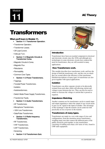
www.learnabout-electronics.orgTransformersFig 11.2.1 Electrical and Magnetic Circuits compared.Electrical and magnetic circuits aresimilar in many respects. Fig. 11.2.1compares a simple electrical andsimple magnetic circuit.In the electrical circuit an e.m.f.produced by a cell or battery drivesa current around the circuit, whichconsists of a length of wire havingsome resistance R.The magnetic circuit also has asource of power in the form of acoil, supplied by an AC current. Justas the external electrical source iscalled an electro motive force, theexternal magnetic source is called amagneto motive force (m.m.f.), andis measured in ampere turns.An e.m.f. produces a current (I),which has a strength measured inamperes in the electrical circuit; inthe magnetic circuit, the m.m.f.produces a magnetic flux, Φ and ismeasured in units of webers (Wb).The resistance to the flow of magnetic flux in the core is called Reluctance ( Rm )Fig 11.2.1Fig 11.2.2 Magnetic Flux linking primary and secondary windings.Figure 11.2.2 shows a magneticcircuit made from a rectangularshaped iron loop or core. A coil (theprimary) supplied with an ACcurrent is wound around one side ofthe core to provide a source ofm.m.f. On the other side of the core,a separate coil (the secondary) iswound which supplies a measuringinstrument to measure the amountof current in the coil. The current inthis coil will be proportional to theamount of flux flowing in the core.This arrangement therefore providesa means of measuring magnetic flux.AC THEORY MODULE 11.PDFFig 11.2.26 E. COATES 2007 -2011
www.learnabout-electronics.orgTransformersFig 11.2.3 Flux is proportional to current and number of turns.Fig 11.2.3Figure 11.2.3 shows that by changing the number of turns on the primary coil, or the currentthrough it, a different amount of current will flow in the secondary coil showing that the flux (Φ) isproportional to both the current and the number of turns. Φ NI.Fig 11.2.4 Flux is also affected by the dimensions of the core.Fig 11.2.4Figure 11.2.4 shows that if the m.m.f. is kept constant, but the dimensions of the core are altered bychanging either the length of the flux path or its cross sectional area, the amount of flux flowingaround the core will also change.Therefore the measured flux (Φ) in the core (and therefore the secondary current) is proportional tothe cross sectional area of the core, and inversely proportional to the length of the flux path:AC THEORY MODULE 11.PDF7 E. COATES 2007 -2011
www.learnabout-electronics.orgTransformersWhere:A is the cross sectional area of the core andL is the mean length of the flux path around the core.The magnetic circuit also has some Reluctance Rm (a type of resistance to flux);Reluctance is measured inAmperes per Weber (A/Wb).Permeability.Electrical resistance also depends not only on the dimensions of the conductor but also on thematerial of the conductor and its resistivity. Likewise, in magnetic circuits reluctance depends notonly on the length and cross sectional area, but also on the Permeability (µ) of the material.The higher the value for µ the more flux will flow and the more flux that flows, the lower must bethe value of reluctance RmTherefore:So Reluctance increases with the length of the magnetic path (l) and decreases as either the crosssectional area (A) of the core or the Permeability (µ) of the material is increased.Relative and Absolute PermeabilityPermeability is often expressed as:µ µ0 µrIt is normal to find a core material described by its relative permeability (µr ), i.e. by how many times the absolutepermeability (µ) of the material is greater than the absolute permeability of free space (µ0 ). The absolute-7-6permeability of free space µ0 has a value of 4 π x 10 H/m 1.256637061 x 10 H/m where H is in henrys and mis in metres. Quoting the absolute permeability of materials used in cores would involve similarly awkwardnumbers. If a more convenient figure, the relative permeability of free space (or
AC THEORY MODULE 11.PDF 3 E. COATES 2007 -2011 Transformation Ratio. Basic Transformer operation can be described by two formulae relating the transformation ratio to the turns ratio of the transformer windings. VP the primary voltage.