Transcription
Power Electronics LaboratoryUser ManualDepartment of Electrical and ComputerEngineeringUniversity of MinnesotaRevised: September 8, 2011Rev ESAFETY WARNINGBefore using this laboratory, read, understand and follow the Safety Precautionsmentioned inside this manual.This is an educational laboratory where high-voltage terminals and large current-carryingcomponents and circuits are exposed for ease of measurements. Therefore, regardless of thevoltage and current levels, these should be treated as high voltages and high currents, and owed.
ContentsExp. #TitlePageSafety Precautions31.Laboratory and Power-pole Board Familiarization62.Buck Converter163.Switching Characteristic of MOSFET and Diode204.Boost Converter235.Buck-Boost Converter266.Voltage-Mode Control307.Peak Current Mode Control368.Flyback Converter419.Forward Converter45Appendix492
SAFETY PRECAUTIONS1. Why is safety important?Attention and adherence to safety considerations is even more important in a power electronicslaboratory than is required in any other undergraduate electrical engineering laboratories. Powerelectronic circuits can involve voltages of several hundred volts and currents of several tens ofamperes. By comparison the voltages in many teaching laboratories rarely exceed 20V and thecurrents hardly ever exceed a few hundred milliamps.In order to minimize the potential hazards, we will use dc power supplies that never exceedvoltages above 40-50V and will have maximum current ratings of 5A or less. However in spiteof this precaution, power electronics circuits on which the student will work may involvesubstantially larger voltages (up to hundreds of volts) due to the presence of large inductances inthe circuits and the rapid switching on and off of amperes of current in the inductances. Forexample a boost converter can have an output voltage that can theoretically go to infinite valuesif it is operating without load. Moreover the currents in portions of some converter circuits maybe many times larger than the currents supplied by the dc supplies powering the convertercircuits. A simple buck converter is an example of a power electronics circuit in which the outputcurrent may be much larger than the input dc supply current2. Potential problems presented by Power Electronic circuits Electrical shock may take a life. Exploding components (especially electrolytic capacitors) and arcing circuits cancause blindness and severe burns. Burning components and arcing can lead to fire.3. Safety precautions to minimize these hazards3.1 General Precautions Be calm and relaxed, while working in Lab. When working with voltages over 40V or with currents over 10A, there must beat least two people in the lab at all times. Keep the work area neat and clean. No paper lying on table or nearby circuits. Always wear safety glasses when working with other than signal-level power.3
Use rubber door mats to insulate yourself from ground, whenworking in the Lab. Be sure about the locations of fire extinguishers and first aid kits in lab. A switch should be included in each supply circuit so that when opened, theseswitches will de-energize the entire setup. Place these switches so that you canreach them quickly in case of emergency, and without reaching across hot or highvoltage components.3.2 Precautions to be taken when preparing a circuit Use only isolated power sources (either isolated power supplies or AC powerthrough isolation power transformers). This helps in using a groundedoscilloscope. This reduces the possibility of risk of completing a circuit throughyour body. This also reduces the possibility of destroying the test equipment.3.3 Precautions to be taken before powering the circuit Check for all the connections of the circuit and scope connections beforepowering the circuit, to avoid shorting or any ground looping, that may lead toelectrical shocks or damage of equipment. Check any connections for shorting two different voltage levels. Check if you have connected load at the output. This is very important in Boostand Buck-Boost Converters and converters based on them. Double check your wiring and circuit connections. It is a good idea to use a pointto-point wiring diagram to review when making these checks.3.4 Precautions while switching ON the circuit Apply low voltages or low power to check proper functionality of circuits. Once functionality is proven, increase voltages or power, stopping at frequentlevels to check for proper functioning of circuit or for any components is hot orfor any electrical noise that can affect the circuit’s operation.3.5 Precautions while switching on or shutting down the circuit Reduce the voltage or power slowly till it comes to zero. Switch of all the power supplies and remove the power supply connections.4
Let the load be connected at the output for some time, so that it helps to dischargecapacitor or inductor if any, completely.3.6 Precautions while modifying the circuit Switch on the circuit as per the steps in section 3.5. Modify the connections as per your requirement. Again check the circuit as per steps in section 3.3, and switch ON as per steps insection 3.4.3.7 Other Precautions No loose wires or metal pieces should be lying on table or near the circuit, tocause shorts and sparking. Avoid using long wires, that may get in your way while making adjustments orchanging leads. Keep high voltage parts and connections out of the way from accidental touchingand from any contacts to test equipment or any parts, connected to other voltagelevels. When working with inductive circuits, reduce voltages or currents to near zerobefore switching open the circuits. BE AWARE of bracelets, rings, metal watch bands, and loose necklace (if you arewearing any of them), they conduct electricity and can cause burns. Do not wearthem near an energized circuit. Learn CPR and keep up to date. You can save a life. When working with energized circuits (while operating switches, adjustingcontrols, adjusting test equipment), use only one hand while keeping the rest ofyour body away from conducting surfaces.5
Experiment 1Laboratory and Power-pole Board Familiarization1.1 IntroductionThe power electronics laboratory is built around a reconfigurable circuit board, termed thePower-pole board, along with accessory daughterboards. The details of the Power-pole board arediscussed in later sections of this experiment. This first experiment will familiarize you with thelaboratory equipment and Power-pole circuit board.1.2 Laboratory EquipmentEach experiment station has the following equipment. Digital Oscilloscope with RS232 interface Function generator DC power supply 0-60 V - 2 A max 12 V Signal Power Supply (with DIN connector output) Differential voltage probe Power Pole circuit board and associated plug-in boards with magnetic components anddaughterboards with onboard components for implementing closed loop control. Digital Multimeter Desktop computer with software for capturing oscilloscope data via RS232 port.Note: The lab instructor will demonstrate how to use the software to capture oscilloscopewaveforms. Students should bring floppy disks or flash drives to download the capturedwaveforms or data for use in their lab reports.This equipment will be used to set up the circuits and to perform most measurements. Thelaboratory will also have several miscellaneous components including power resistors, magneticsboards, hookup wire, etc. as needed for specific experiments.1.3 Power-pole Board FamiliarizationThe main feature of the Power-pole Board is the reconfigurable power-pole consisting of twoMOSFETs and two diodes. The drive circuits for the MOSFETs are incorporated on the board,and so are the various protection circuits for over current and over voltage. PWM signals tocontrol the MOSFETs can be generated onboard or supplied from an external source. The powerpole can be configured to work in various topologies using three magnetics boards (BB board for6
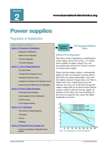
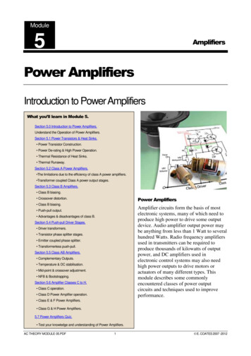
buck, boost and buck-boost converters, Flyback board for flyback converter, and Forward boardfor forward converter) which plug into the Power-pole Board. In addition, there is an option ofdoing frequency analysis of each topology by injecting a small-signal sinusoidal control voltage.The board can also be operated in voltage/current feedback mode using an external controlcircuit mounted on a daughter board which plugs into the Power-pole Board.The basic block diagram of the Power-pole Board is shown in Fig. 1.1 and the actual board isshown in Fig. 1.2. Please note that the locations of the various components on the board areindicated in Table 1.1.1.3.1 Power-poleThe power-pole consists of MOSFETs Q10 and Q15 and diodes D10 and D15. The source of theupper MOSFET and the drain of the lower MOSFET are connected to screw terminals forexternal connection, and so are the anode of upper diode and the cathode of the lower diode. Thevoltage and current waveforms at the terminals of the MOSFETs and diodes can be observed.Table 1.2 shows the locations of test points on the power pole board.Note:Take care whenever you are using oscilloscope probes to measure voltage. If the measurementreference potential is different to the oscilloscope reference potential, you must use differentialprobe.To observe the voltage across the upper MOSFET, Connect the positive and negative terminals of a differential probe to the DRAIN andSOURCE of upper MOSFET.To observe the upper MOSFET source current, Connect the positive and negative terminals of a differential probe to terminals CS2 andSOURCE (D-2 in Fig. 1.2) of upper MOSFET. The current sense resistor value is 0.05 Ω.7
Figure 1.1: Block diagram of Power-pole Board.8
Figure 1.2: Power-Pole board.9
Table 1.1: Location of components on Power-Pole 62728293031323334ComponentTerminal V1 Terminal V2 Terminal COM (input)Terminal COM (output)DIN connector for 12 V signal supplySignal supply switchSignal supply 12 V fuseSignal supply 12 V fuseSignal supply LEDFault LEDOver voltage LEDOver current LEDUpper MOSFET , diode and heat sink assemblyLower MOSFET , diode and heat sink assemblyScrew terminal for upper MOSFET sourceScrew terminal for lower diode cathodeScrew terminal for upper diode anodeScrew terminal for lower MOSFET drainScrew terminal for Mid-pointMagnetics Board plug-in spacePWM Controller UC3824Duty ratio pot RV64Switching frequency adjustment pot RV60External PWM signal input terminalSelector Switch BankDaughter board connectorSwitched loadResettable FuseControl selection jumpersRamp select jumperCurrent limit jumperSmall-signal ac analysis selection jumperInput current sensor (LEM)Output current sensor (LEM)Ref. Des.J1J21J2J22J90S90F90F95D99D32D33D34Q15, D15Q10, , J63J61J65J64CS1CS5Location inFig. -1K-210
Table 1.2: Test Point Details and Location on Power-pole BoardNo.Test Point1234567891011111212131314141516V1 V2 CS1CS2CS3CS4CS5CS LOAD 1CS LOAD 2PWMDRAIN (upper MOSFET )SOURCE (upper MOSFET )DRAIN (lower MOSFET )SOURCE (lower MOSFET )ANODE (upper diode)CATHODE (upper diode)ANODE (lower diode)CATHODE (lower diode)GATE (upper MOSFET )GATE (lower MOSFET )Description of Test PointTerminal V1 Terminal V2 Input currentUpper MOSFET source currentLower diode or MOSFET source currentOutput Capacitor CurrentOutput currentSwitched Load Voltage veSwitched Load Voltage -vePWM SignalUpper MOSFET drainUpper MOSFET sourceLower MOSFET drainLower MOSFET sourceUpper diode anodeUpper diode cathodeLower diode anodeLower diode cathodeGate of upper MOSFETGate of lower MOSFETLocationin Fig. 2D-4D-4C-2C-4To observe the voltage across the lower MOSFET , Connect an oscilloscope probe to the DRAIN and its ground to the SOURCE (E-4 in Fig.1.2) of the lower MOSFET.To observe the lower MOSFET source current, Connect an oscilloscope probe to terminal CS3 and its ground to the SOURCE (E-4 inFig. 1.2) of the lower MOSFET. The current sense resistor value is 0.05 Ω. The sametest points also measure the lower diode current if that is included in the circuit.To observe the voltage across the upper diode, Connect the positive and negative terminals of a differential probe to terminal CATH andANODE (E-2 in Fig. 1.2) of the upper diode.To observe the voltage across the lower diode, Connect an oscilloscope probe to CATHLOW and its ground to the ANODE of the lowerdiode (D-4 in Fig. 1.2).11
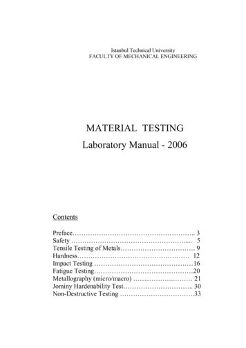
1.3.2 Magnetics BoardsTo build various converters using the Power-pole Board , three plug in boards are provided:1. BB Board (Fig. 1.3(a)): For buck, boost and buck-boost converters2. Flyback Board (Fig. 1.3(b)): For flyback converter3. Forward Board (Fig. 1.3(c)): For forward converterHow to use these boards will be described in the subsequent experiments.(a) BB Board(b) Flyback Board(c) Forward BoardFigure 1.3: Magnetics boards.1.3.3 Signal Supply 12 volts signal supply is required for the MOSFET drive circuits and also the measurement andprotection circuits. This is obtained from a wall-mounted isolated power supply, which plugsinto the DIN connector J90 (A-5 in Fig. 1.2). Switch S90 (B-6 in Fig. 1.2) controls the signalpower to the board. Each time a fault occurs, turn off and turn on this switch to reset the board.The green LED D99 (B-5 in Fig. 1.2) indicates if the 12 V signal supply is available to theboard. Fuses F90 (B-5 in Fig. 1.2) and F95 (B-6 in Fig. 1.2) provide protection for the 12 V and-12 V supplies respectively.1.3.4 LoadAny external load is to be connected across terminals V2 and COM (L-1 and L-6 in Fig. 1.2).An onboard switched load is provided to facilitate the observation of the transient response ofany converter built using the power-pole. Thus it is possible to periodi
08.09.2011 · Power Electronics Laboratory User Manual Department of Electrical and Computer Engineering University of Minnesota Revised: September 8, 2011 Rev E SAFETY WARNING Before using this laboratory, read, understand and follow the Safety Precautions mentioned inside this manual. This is an educational laboratory where high-voltage terminals and large current-carrying components File Size: 823KBPage Count: 51