Transcription
An Introduction toCATIA V6 Release 2012A Hands-On Tutorial ApproachKirstie PlantenbergSDCP U B L I C AT I O N SSchroff Development CorporationBetter Textbooks. Lower Prices.www.SDCpublications.com
Visit the following websites to learn more about this book:
Chapter 2: SKETCHER: Tutorial 2.2Chapter 2:SKETCHERTutorial 2.2: Simple Profiles &ConstraintsFEATURED TOPICS & COMMANDSPROFILE TOOLBAR . 2Profile toolbar . 2Predefined Profile toolbar . 3Circle toolbar . 3Spline toolbar . 4Conic toolbar . 4Line toolbar . 4Point toolbar . 4CONSTRAINT TOOLBAR . 5SELECTING ICONS . 5TUTORIAL 2.2 START . 6Section 1: Creating circles. . 6Section 2: Creating dimensional constraints. . 8Section 3: Creating lines. . 9Section 4: Creating geometrical constraints. . 13Section 5: Creating arcs . 16Section 6: Adding Text . 19PREREQUISITE KNOWLEDGE & COMMANDS Entering workbenchesEntering and exiting the Sketcher workbenchSimple PadsWork modes (Sketch tools toolbar)2.2 - 1
Chapter 2: SKETCHER: Tutorial 2.2PROFILE TOOLBARThe Profile toolbar contains 2D geometry commands. These geometries rangefrom the very simple (point, rectangle, etc.) to the very complex (splines, conics, etc.).The Profile toolbar contains many sub-toolbars. Most of these sub-toolbars containdifferent options for creating the same geometry. For example, you can create a simpleline, a line defined by two tangent points, or a line that is perpendicular to a surface.Profile toolbarReading from left to right, the Profile toolbar contain the following commands. Profile: This command allows you to create a continuous set of lines and arcsconnected together.Rectangle / Predefined Profile toolbar: The default top command is rectangle.Stacked underneath are several different commands used to create predefinedgeometries.Circle / Circle toolbar: The default top command is circle. Stacked underneath areseveral different options for creating circles and arcs.Spline / Spline toolbar: The default top command is spline which is a curved linecreated by connecting a series of points.Ellipse / Conic toolbar: The default top command is ellipse. Stacked underneath arecommands to create different conic shapes such as a hyperbola.Line / Line toolbar: The default top command is line. Stacked underneath areseveral different options for creating lines.Axis: An axis is used in conjunction with commands like mirror and shaft (revolve).It defines symmetry. It is a construction element so it does not become a physicalpart of your feature.Point / Point toolbar: The default top command is point. Stacked underneath areseveral different options for creating points.2.2 - 2
Chapter 2: SKETCHER: Tutorial 2.2Predefined Profile toolbarPredefined profiles are frequently used geometries. CATIA makes these profilesavailable for easy creation which speeds up drawing time. Reading from left to right, thePredefined Profile toolbar contains the following commands. Rectangle: The rectangle is defined by twocorner points. The sides of the rectangleare always horizontal and vertical.Oriented Rectangle: The oriented rectangleis defined by three corner points. This allows you to create a rectangle whose sidesare at an angle to the horizontal.Parallelogram: The parallelogram is defined by three corner points.Elongated Hole: The elongated hole or slot is defined by two points and a radius.Cylindrical Elongated Hole: The cylindrical elongated hole is defined by a cylindricalradius, two points and a radius.Keyhole Profile: The keyhole profile is defined by two center points and two radii.Hexagon: The hexagon is defined by a center point and the radius of an inscribedcircle.Centered Rectangle: The centered rectangle is defined by a center point and acorner point.Centered Parallelogram: The centered parallelogram is defined by a center point(defined by two intersecting lines) and a corner point.Text: Creates text that may be used to create a solid.Circle toolbarThe Circle toolbar contains several different ways of creating circles and arcs.Reading from left to right, the Circle toolbar contains the following commands. Circle: A circle is defined by a center point and aradius.Three Point Circle:The three point circlecommand allows you to create a circle usingthree circumferential points.Circle Using Coordinates: The circle using coordinates command allows you tocreate a circle by entering the coordinates for the center point and radius in a CircleDefinition window.Tri-Tangent Circle: The tri-tangent circle command allows you to create a circlewhose circumference is tangent to three chosen lines.Three Point Arc: The three point arc command allows you to create an arc definedby three circumferential points.Three Point Arc Starting With Limits: The three point arc starting with limits allowsyou to create an arc using a start, end, and midpoint.Arc: The arc command allows you to create an arc defined by a center point, and acircumferential start and end point.2.2 - 3
Chapter 2: SKETCHER: Tutorial 2.2Spline toolbarReading from left to right, the Spline toolbar contains the following commands. Spline: A spline is a curved profile defined by three or more points.The tangency and curvature radius at each point may be specified.Connect: The connect command connects two points or profiles witha spline.Conic toolbarReading from left to right, the Conic toolbar contains the following commands. Ellipse: The ellipse is defined by a center point and majorand minor axis points.Parabola by Focus: The parabola is defined by a focus, apexand start and end points.Hyperbola by Focus: The hyperbola is defined by a focus, center point, apex andstart and end points.Conic: There are several different methods that can be used to create conic curves.These methods give you a lot of flexibility when creating the above three types ofcurves.Line toolbarThe Line toolbar contains several different ways of creating lines. Reading fromleft to right, the Line toolbar contains the following commands. Line: A line is defined by two points.Infinite Line: Creates infinite lines that are horizontal,vertical or defined by two points.Bi-Tangent Line: Creates a line whose endpoints aretangent to two other elements.Bisecting Line: Creates an infinite line that bisects the angle created by two otherlines.Line Normal to Curve: This command allows you to create a line that startsanywhere and ends normal or perpendicular to another element.Point toolbarThe Point toolbar contains several different ways of creating points. Readingfrom left to right, the Point toolbar contains the following commands. Point by Clicking: Creates a point by clicking the leftmouse button.Point by using Coordinates: Creates a point at aspecified coordinate point.2.2 - 4
Chapter 2: SKETCHER: Tutorial 2.2 Equidistant Points: Creates equidistant points along a predefined path curve.Intersection Point: Creates a point at the intersection of two different elements.Projection Point: Projects a point of one element onto another.CONSTRAINT TOOLBARConstraints can either be dimensional or geometrical. Dimensional constraintsare used to constrain the length of an element, the radius or diameter of an arc or circle,and the distance or angle between elements.Geometrical constraints are used to constrain theorientation of one element relative to another. Forexample, two elements may be constrained to beperpendicular to each other. Other common geometricalconstraints include parallel, tangent, coincident,concentric, etc. Reading from left to right: Constraints Defined in Dialoged Box:Createsgeometrical and dimensional constraints between two elements.Constraint: Creates dimensional constraints.o Contact Constraint: Creates a contact constraint between two elements.Fix Together: The fix together command groups individual entities together.o Auto Constraint: Automatically creates dimensional constraints.Animate Constraint: Animates a dimensional constraint between to limits.Edit Multi-Constraint: This command allows you to edit all your sketch constraints ina single window.SELECTING ICONSWhen an icon is selected, it turns orange indicating that it is active. If the icon isactivated with a single mouse click, the icon will turn back to blue (deactivated) when theoperation is complete. If the icon is activated with a double mouse click, it will remainactive until another command is chosen or if the Esc key is hit twice.2.2 - 5
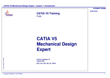
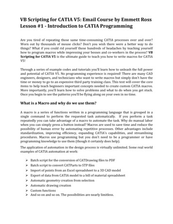
Chapter 2: SKETCHER: Tutorial 2.2TUTORIAL 2.2 STARTThe part modeled in this tutorial isshown on the right. This part will be createdusing simple profiles, circles, arcs, lines, andhexagons. The geometries are constrained toconform to certain dimensional (lengths) andgeometrical constraints (tangent, perpendicular,etc.).Section 1: Creating circles.(Hint: If you get confused about how toapply the different commands that are used inthis tutorial, read the Status Bar for additionalhelp.)1) Open a New 3D Part and name your partand its representation T22Post.2) Make your PartBody the In Work Object.3) Enter the Sketcher4) Turn your Gridon the zx plane.on.2.2 - 6
Chapter 2: SKETCHER: Tutorial 2.25) Set your grid spacing to be 100 mm with 10 graduations, activate the Snap to point,and activate the geometrical and dimensional constraints. (Tools – Options.)Duplicate thesettings shown.6) Pull out the Circle subtoolbar.2.2 - 7
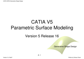
Chapter 2: SKETCHER: Tutorial 2.27) Double click on the Circleicon and draw the circlesshown. Don't worry about the size, just make sure that thecircle centers are in line with the V axis.8) Exit the SketcherandPadthe sketch to12 mm on eachside(Mirroredextent).Noticethat the inner circleatthebottombecomes a hole.Section 2: Creating dimensional constraints.1) Expand your specificationtree to the sketch level.2) Edit Sketch.1.To edit asketch you can double clickon the sketch name in thespecification tree, or you canright click on the name selectSketch.1 - Edit.CATIAautomatically takes you intothe sketcher on the planeused to create Sketch.1.3) Double click on the Constraintsicon.4) Select the border of the upper circle, pull thedimension out and click your left mouse button toplace the dimension. Repeat for the two bottomcircles.5) Select the center point of the upper circle, then thecenter point of the lower circles, pull the dimension out and click.2.2 - 8
Chapter 2: SKETCHER: Tutorial 2.26) Double click on the dimensions to edit their sizes.In the Constraint Definition window, change thedimensions to what you see in the figure.D48140807) Exit the Sketcherand deselect all. Noticethat the part automatically updates to the newsketch dimensions.D16D32Section 3: Creating lines.1) Deselect all.2) Enter the Sketcheron the zx plane.3) Deactivate the Snap to Pointicons.and the Construction/Standard Elements4) Project the two outer circles of the part onto the sketch plane as Standard elements.Double click on the Project 3D Elementsicon. This icon is located in theOperation toolbar in the right side toolbar area. Select the outer edges of the twocylinders. If done correctly, the circumference of each circle will be outlined by ayellow circle.5) Pull out the line toolbar6) PullouttheRelimitations.toolbar2.2 - 9locatedintheOperationtoolbar.
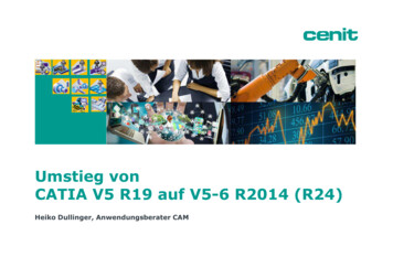
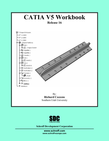
Chapter 2: SKETCHER: Tutorial 2.27) Double click on the Bi-Tangent LineProjected edgeTrimmed edgeicon. Draw two tangent lines byselecting the points, in order, asindicated on the figure.138) Double click on the Quick trimicon. Select the outer portion of theprojected circles.Notice that thetrimmed projection turns into aconstruction element (dashed).9) ExittheSketcherand Padthe sketch to 6 mmoneachside(Mirrored extent).Projected edge2Trimmed edge2.2 - 104
Chapter 2: SKETCHER: Tutorial 2.210) Propagate11) Enter the Sketcheron the zx plane.12) Activate the Construction/Standard Elementicon (it should be orange).13) Select the Project 3D Elementsicon andthen project the left line of the part as shown in thefigure. The projected line should be dashed.14) Activate your Snap to Pointicon.Projected line15) Draw a Linefrom point 1 to the origin andanother Line from point 1 to point 2.16) Draw a line that bisects the previous 2 lines usingthe Bisecting Lineline for directions.icon. Read the prompt1Bisecting line17) Deactivate your Snap to Pointicon.18)
An Introduction to CATIA V6 Release 2012 A Hands-On Tutorial Approach Kirstie Plantenberg SDC PUBLICATIONS www.SDCpublications.com Better Textbooks. Lower