Transcription
Introduction to CATIA V5Release 16(A Hands-On Tutorial Approach)Kirstie PlantenbergUniversity of Detroit MercySDCPUBLICATIONSSchroff Development Corporationwww.schroff.comwww.schroff-europe.com
Visit the following websites to learn more about this book:
An Introduction to CATIA V5Chapter 2: SKETCHERCopyrightedChapter 2: SKETCHERMaterialIntroductionChapter 2 focuses on CATIA’s Sketcher workbench. The reader will learn how tosketch and constrain very simple to very complex 2D profiles.CopyrightedMaterialTutorials Contained in Chapter 2 Tutorial 2.1: Sketch Work ModesTutorial 2.2: Simple Profiles & ConstraintsTutorial 2.3: Advanced Profiles & Sketch AnalysisTutorial 2.4: Modifying Geometries & RelimitationsTutorial 2.5: Axes & TransformationsTutorial 2.6: Operations on 3D Geometries & Sketch planesTutorial 2.7: Points & SplinesCopyrightedMaterialCopyrightedMaterial2-1
An Introduction to CATIA V5Chapter 2: alCopyrightedMaterialCopyrightedMaterial2-2
Chapter 2: SKETCHER: Tutorial 2.1CopyrightedChapter 2:SKETCHERMaterialTutorial 2.1: Sketch WorkModesCopyrightedMaterialFeatured Topics & CommandsThe Sketcher workbenchThe Sketch tools toolbarPart ModeledSection 1: Using Snap to PointSection 2: Using Construction ElementsSection 3: Geometrical and Dimensional ConstraintsSection 4: Cutting the part by the sketch plane.CopyrightedMaterialPrerequisite Knowledge & Commands Entering workbenchesEntering and exiting the Sketcher workbenchDrawing simple profilesSimple Pads and PocketsCopyrightedMaterial2.1 - 12.1-22.1-32.1-42.1-42.1-72.1-92.1-11
Chapter 2: SKETCHER: Tutorial 2.1CopyrightedMaterialThe Sketcher WorkbenchThe Sketcher workbench is a set of tools that helps you create and constrain 2Dgeometries. Features (pads, pockets, shafts, etc.) may then be created solids ormodifications to solids using these 2D profiles. You can access the Sketcherworkbench in various ways. Two simple ways are by using the top pull downmenu (Start – Mechanical Design – Sketcher), or by selecting the Sketchericon. When you enter the sketcher, CATIA requires that you choose a plane tosketch on. You can choose this plane either before or after you select theSketcher icon. To exit the sketcher, select the Exit Workbenchicon.CopyrightedMaterialThe Sketcher workbench contains the following standard workbench specifictoolbars. Profile toolbar: The commands locatedin this toolbar allow you to create simplegeometries (rectangle, circle, line, etc.)and more complex geometries (profile,spline, etc.). Operation toolbar: Once a profile has been created,it can be modified using commands such as trim,mirror, chamfer, and other commands located in theOperation toolbar.CopyrightedMaterial Constraint toolbar: Profiles may be constrained l (tangent, parallel, etc.) constraintsusing the commands located in the Constrainttoolbar. Sketch tools toolbar: The commands in thistoolbar allow you to work in different modes whichmake sketching easier. User Selection Filter toolbar: Allows you toactivate different selection filters.CopyrightedMaterial2.1 - 2
Chapter 2: SKETCHER: Tutorial 2.1 Visualization toolbar: Allows you to, amongother things to cut the part by the sketchplane and choose lighting effects and otherfactors that influence how the part isvisualized. Tools toolbar: Allows you to, among others otherthings, to analyze a sketch for problems, and createa datum.CopyrightedMaterialThe Sketch tools ToolbarThe Sketch tools toolbar contains icons that activate and deactivate differentwork modes. These work modes assist you in drawing 2D profiles. Reading fromleft to right, the toolbar contains the following work modes; (Each work mode isactive if the icon is orange and inactive if it is blue.) CopyrightedMaterialGrid: This command turns the sketcher grid onand off.Snap to Point: If active, your cursor will snap to theintersections of the grid lines.Construction / Standard Elements: You can draw two different types ofelements in CATIA a standard element and a construction element. Astandard element (solid line type) will be created when the icon is inactive(blue). It will be used to create a feature in the Part Design workbench. Aconstruction element (dashed line type) will be created when the icon is active(orange). They are used to help construct your sketch, but will not be used tocreate features.Geometric Constraints: When active, geometric constraints will automaticallybe applied such as tangencies, coincidences, parallelisms, etc.Dimensional Constraints: When active, dimensional constraints willautomatically be applied when corners (fillets) or chamfers are created, orwhen quantities are entered in the value field. The value field is a place wheredimensions such as line length and angle are manually entered.CopyrightedMaterialCopyrightedMaterial2.1 - 3
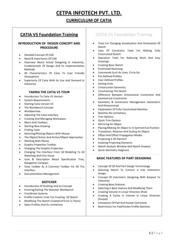
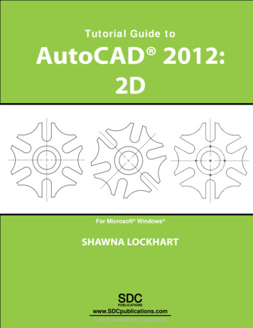
Chapter 2: SKETCHER: Tutorial 2.1CopyrightedMaterialPart ModeledThe part modeled inthis tutorial is shownbelow. The part isconstructed with theassistance ofdifferent workmodes.CopyrightedMaterialSection 1: Using Snap to Point1) Open a New Part drawing and name the part Spline Shape.CopyrightedMaterial2) Enter the Sketcheron the yz plane.3) Restore the default positions of the toolbars (Tools – Customize. –Toolbars tab – Restore position.) Move the Sketch Tools toolbar and theUser Selection Filter toolbar to the top toolbar area.CopyrightedMaterial2.1 - 4
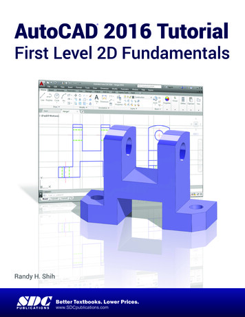
Chapter 2: SKETCHER: Tutorial 2.1CopyrightedMaterial4) Set your grid spacing. At the top pull down menu, select Tools – Options. Inthe Options window, expand the Mechanical Design portions of the left sidenavigation tree and select Sketcher. Activate the options Display, Snap topoint, and Allow Distortions in the Grid section on the right side. Set yourPrimary spacing and Graduations to H: 100 mm and 20, and V: 100 mm and10.CopyrightedMaterialCopyrightedMaterial5) Select the Splineside toolbar area.icon. This is located in the Profile toolbar in the right6) Move your cursor around the screen. Note that it snaps to the intersections ofthe grid. Your Snap to Pointshould be orange (active). Deactivate theSnap to Pointicon by clicking on it and turning it back to blue. Moveyour cursor around the screen and notice the difference.CopyrightedMaterial2.1 - 5
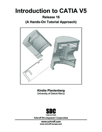
Chapter 2: SKETCHER: Tutorial 2.1CopyrightedMaterial7) ReactivatetheSnaptoPointicon and drawthe spline shown. Selecteach point (indicated by anumber in a square) in orderfrom 1 to 7, double clickingat the last point to end thespline command.8) Edit the spline by doubleclicking on any portion of it.217346CopyrightedMaterial9) In the Spline Definitionwindow, select CtrlPoint.7,then activate the Tangencyoption, and select OK.Notice that the last point isnow tangent to the firstpoint.5CopyrightedMaterial10) Draw a Circleas shown.inside the splineCopyrightedMaterial2.1 - 6
Chapter 2: SKETCHER: Tutorial 2.1CopyrightedMaterial11) Exit the Sketcherto a length of 50 mm.and Padthe sketchCopyrightedMaterialSection 2: Using construction elements.1) Deselect all.2) Enter the Sketcherface of the part.on the frontSketch faceCopyrightedMaterial3) Activate the Construction / StandardElementsorange.icon. It should be4) Deselect all. Hit the Esc key twice.5) Project an outline of the part onto the sketch plane. Select the Project 3DElementsicon then select the face of the part. This icon is located inthe Operations toolbar near the bottom of the right side toolbar area. It maybe hidden in the bottom right corner.CopyrightedMaterial6) Deselect all. The projection should now be yellow (this means it is associatedwith the part and will change with the part) and dashed (this means it is aconstruction element).2.1 - 7
Chapter 2: SKETCHER: Tutorial 2.1CopyrightedMaterial7) At the top pull down window, select Tools – Options – Sketcher tab.Deactivate the Grid Display and Snap to Point options. Select OK.CopyrightedMaterial8) Deactivate the Construction / Standard Elementsicon.command to draw the triangle shown. The points of the9) Using the Profiletriangle should lie on the projected construction element. You will know whenyou are on the projection when a symbol of two concentric circles appears,and you will know when you are snapped to the endpoint of the start pointwhen a symbol of two concentric circles appears and the inner one is filled.CopyrightedMaterialCopyrightedMaterial2.1 - 8
Chapter 2: SKETCHER: Tutorial 2.1CopyrightedMaterial10) Exit the Sketcherto a length of 10 mm.and Padthe sketchCopyrightedMaterialSection 3: Geometrical and Dimensional Constraints1) Deselect all.2) Enter the Sketcheron thefront large face of the part.CopyrightedMaterial3) Activate the GeometricalConstraintsorange.icon. It should beSketch face4) At the top pull down window, select Tools – Options – Sketcher. Under theConstraint portions of the window, select SmartPick. The SmartPick windowshows all the geometrical constraints that will becreated automatically. These constraints may beturn on and off depending on your design/sketchneeds. Close both the Smart Pick and Optionswindows.CopyrightedMaterial2.1 - 9
Chapter 2: SKETCHER: Tutorial 2.1CopyrightedMaterial5) Draw a Rectangleto theright of the hole as shown.Noticethatgeometricconstraints (H horizontal, V Vertical) are automaticallyapplied.6) Deactivate the GeometricalConstraintsshould be blue.icon.ItCopyrightedMaterial7) Draw a Rectangleto theleft of the hole as shown.Notice that no geometric constraintsare made.Click and dragthe corner point.8) For each rectangle, click on one of the points defining a corner and move itusing the mouse. Notice the difference between the two. This is due to thehorizontal and vertical constraints that were applied to the one rectangle.9) Undo (CTRL Z) the moves until the original rectangles are back.CopyrightedMaterial10) Exit the Sketcherand Pocketsketch using the Up to last option.theCopyrightedMaterial11) Expand the specification tree to the sketch level.2.1 - 10
Chapter 2: SKETCHER: Tutorial 2.1CopyrightedMaterial12) Edit Sketch.3 (the sketch associated with the pocket). In the specificationtree, double click on Sketch.3, or right click on it and select Sketch.3 object Edit. You will automatically enter the sketcher on the sketch plane used tocreate this sketch.13) Activate the Dimensional Constrainticon. It should be orange.icon, select14) Select the Cornerthe bottom left corner point of the leftrectangle, move your mouse up andto the right, and click. A corner orfillet will be created. The corner iconis located in the Operations toolbarnear the bottom of the right sidetoolbar area. The corner/filletmay also be created by Corner pointselecting the two lines thatcreate the corner. Notice that adimension is automatically created.CopyrightedMaterial15) Deactivate the DimensionalConstrainticon. It should beCopyrightedMaterialblue. Create a Cornerin theupper right corner of the samerectangle. Notice that this time nodimensional constraint was created.16) Exit the Sketcher. We havechanged the sketch used to createthe pocket. Notice that the pocket is automatically updated to reflect thesechanges.CopyrightedMaterialSection 4: Cutting the part by the sketch plane.Sometimes it is necessary to sketch inside the part. The Cut Part by SketchPlane command allows you to see inside the part and makes it easier to drawand constrain your sketch.1) Enter the Sketcheron the xy plane.2.1 - 11
Chapter 2: SKETCHER: Tutorial 2.1CopyrightedMaterial2) Select the Isometric Viewarea.icon. This icon is located in the bottom toolbar3) Select the Cut Part by SketchPlaneicon located in thebottom toolbar area. The part innow cut by the xy plane (thesketch plane).CopyrightedMaterial4) Select the Top viewiconand draw a Circlein themiddle of the hole as shownin the figure.5) Exit the Sketcher.6) Select the Padicon andthen select the More button.Fill in the following fields for boththe First and Second Limits;Type: Up to surface, Limit:Select the inner circumference ofthehole,andSelection:Sketch.4 (the circle). SelectPreview to see if the Pad will beapplied correctly, and then OK.CopyrightedMaterialCopyrightedMaterial2.1 - 12
Chapter 2: SKETCHER: Tutorial 2.2CopyrightedChapter 2:SKETCHERMaterialTutorial 2.2: Simple Profiles &ConstraintsCopyrightedMaterialFeatured Topics & CommandsProfile toolbarConstraints toolbarSelecting iconsPart ModeledSection 1: Creating circles.Section 2: Creating dimensional constraints.Section 3: Creating lines.Section 4: Creating geometrical constraints.Section 5: Creating arcs.CopyrightedMaterialPrerequisite Knowledge & Commands Entering workbenchesEntering and exiting the Sketcher workbenchSimple PadsWork modes (Sketch tools toolbar)CopyrightedMaterial2.2 - 12.2-22.2-52.2-52.2-62.2-62.2-72.2-82.2-112.2-14
Chapter 2: SKETCHER: Tutorial 2.2CopyrightedMaterialProfile toolbarThe Profile toolbar contains 2D geometry commands. These geometries rangefrom the very simple (point, rectangle, etc.) to the very complex (splines, conics,etc.). The Profile toolbar contains many sub-toolbars. Most of these subtoolbars contain different options for creating the same geometry. For example,you can create a simple line, a line defined by two tangent points, or a line that isperpendicular to a surface. Reading from left to right, the Profile toolbar
Introduction to CATIA V5 Release 16 (A Hands-On Tutorial Approach) Kirstie Plantenberg University of Detroit Mercy SDC Schroff Development Corporation www.schroff.com www.schroff-europe.com PUBLICATIONS. Visit the following websites to learn more about this book: An Introduction to CATIA V5 Chapter 2: SKETCHER 2 - 1 Chapter 2: SKETCHER Introduction Chapter 2 focuses on CATIA’s File Size: 1MBPage Count: 33