Transcription
CATIA V5 TutorialsMechanism Design & AnimationRelease 18Nader G. ZamaniUniversity of WindsorJonathan M. WeaverUniversity of Detroit MercySDCPUBLICATIONSSchroff Development Corporationwww.schroff.comBetter Textbooks. Lower Prices.
CATIA V5 Tutorials in Mechanism Design and AnimationChapter 4Slider Crank Mechanism4-1
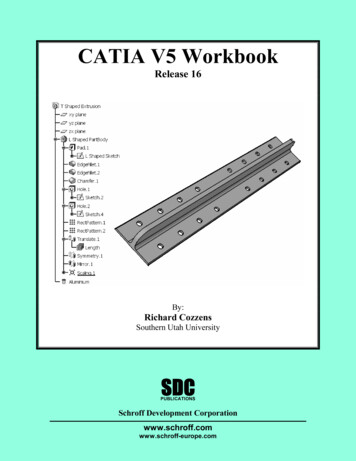
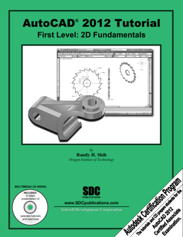
4-2CATIA V5 Tutorials in Mechanism Design and AnimationIntroductionIn this tutorial you create a slider crank mechanism using a combination of revolute andcylindrical joints. You will also experiment with additional plotting utilities in CATIA.1 Problem StatementA slider crank mechanism, sometimes referred to as a three-bar-linkage, can be thoughtof as a four bar linkage where one of the links is made infinite in length. The piston basedinternal combustion is based off of this mechanism. The analytical solution to thekinematics of a slider crank can be found in elementary dynamics textbooks.In this tutorial, we aim to simulate the slider crank mechanism shown below for constantcrank rotation and to generate plots of some of the results, including position, velocity,and acceleration of the slider. The mechanism is constructed by assembling four parts asdescribed later in the tutorial. In CATIA, the number and type of mechanism joints willbe determined by the nature of the assembly constraints applied. There are several validcombinations of joints which would produce a kinematically correct simulation of theslider crank mechanism. The most intuitive combination would be three revolute jointsand a prismatic joint. From a degrees of freedom standpoint, using three revolute jointsand a prismatic joint redundantly constrains the system, although the redundancy doesnot create a problem unless it is geometrically infeasible, in this tutorial we will choosean alternate combination of joints both to illustrate cylindrical joints and to illustrate thatany set of joint which removes the appropriate degrees of freedom while providing thecapability to drive the desired motions can be applied. In the approach suggested by thistutorial, the assembly constraints will be applied in such a way that two revolute jointsand two cylindrical joints are created reducing the degrees of freedom are reduced to one.This remaining degree of freedom is then removed by declaring the crank joint (one ofthe cylindrical joints in our approach) as being angle driven. An exercise left to thereader is to create the same mechanism using three revolute joints and one prismatic jointor some other suitable combination of joints. We will use the Multiplot feature availablein CATIA is used to create plots of the simulation results where the abscissa is notnecessarily the time variable.CylindricalRevoluteRevoluteCylindrical
Slider Crank Mechanism4-32 Overview of this TutorialIn this tutorial you will:1. Model the four CATIA parts required.2. Create an assembly (CATIA Product) containing the parts.3. Constrain the assembly in such a way that only one degree of freedom isunconstrained. This remaining degree of freedom can be thought of as rotation ofthe crank.4. Enter the Digital Mockup workbench and convert the assembly constraints intotwo revolute and two cylindrical joints.5. Simulate the relative motion of the arm base without consideration to time (inother words, without implementing the time based angular velocity given in theproblem statement).6. Add a formula to implement the time based kinematics associated with constantangular velocity of the crank.7. Simulate the desired constant angular velocity motion and generate plots of thekinematic results.
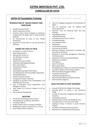
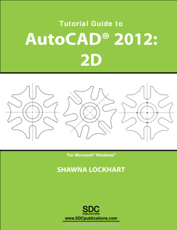
4-4CATIA V5 Tutorials in Mechanism Design and Animation3 Creation of the Assembly in Mechanical Design SolutionsAlthough the dimensions of the components are irrelevant to the process (but not to thekinematic results), the tutorial details provide some specific dimensions making it easierfor the reader to model the appropriate parts and to obtain results similar to those herein.Where specific dimensions are given, it is recommended that you use the indicated values(in inches). Some dimensions of lesser importance are not given; simply estimate thosedimensions from the drawing.In CATIA, model four parts named base, crank, conrod, and block as shown below.base1x1x1 cubeBlockLength 10Diameter 0.5Length 0.75Diameter 0.5Length 0.5crankDiameter 0.51x1 squareDiameter 0.7(4 locations)3.5Diameter 0.5Diameter 0.5Thickness 0.25Diameter 0.5Length 0.35Thickness 0.256.5conrod
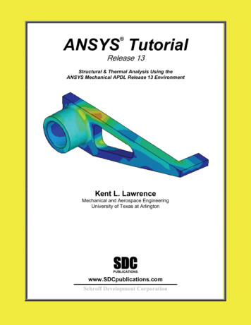
Slider Crank Mechanism4-5Enter the Assembly Design workbenchwhichcan be achieved by different means depending on yourCATIA customization. For example, from the standardWindows toolbar, select File New.From the box shown on the right, select Product. Thismoves you to the Assembly Design workbench andcreates an assembly with the default name Product.1.In order to change the default name, move thecurser to Product.1 in the tree, right clickand select Properties from the menu list.From the Properties box, select theProduct tab and in Part Number typeslider crank.This will be the new product name throughoutthe chapter. The tree on the top left corner ofyour computer screen should look as displayedbelow.The next step is to insert the existing parts in the assembly just created. From thestandard Windows toolbar, select Insert Existing Component.From the File Selection pop up box choose all four parts. Remember that in CATIAmultiple selections are made with the Ctrl key. The tree is modified to indicate that theparts have been inserted.
4-6CATIA V5 Tutorials in Mechanism Design and AnimationNote that the part names and their instance names were purposely made the same. Thispractice makes the identification of the assembly constraints a lot easier down the road.Depending on how your parts were created earlier, on the computer screen you have thefour parts all clustered around the origin. You may have to use the Manipulation iconin the Move toolbarto rearrange them as desired.The best way of saving your work is to save the entire assembly.Double click on the top branch of the tree. This is to ensure that you are in theAssembly Design workbench.Select the Save icon. The Save As pop up box allows you to rename if desired.The default name is the slider crank.
Slider Crank Mechanism4-7Your next task is to impose assembly constraints.from the Constraints toolbar and select the base from thePick the Anchor icontree or from the screen. This removes all six degrees of freedom for the base.Next, we will create a coincident edge constraint between the base and the block. Thisremoves all dof except for translation along the edge of coincidence and rotation aboutthe edge of coincidence. The two remaining dof are consistent with our desire to create acylindrical joint between the block and the base. To make the constraint, pick theCoincidence iconfrom the Constraints toolbar. Select the two edges of the base and theblock as shown below.This constraint is reflected in the appropriate branch of the tree.Select this edge of baseSelect this edge of blockUse Update iconto partially position the two parts as shown.Note that the Update iconno longer appears on the constraints branches.
4-8CATIA V5 Tutorials in Mechanism Design and AnimationDepending on how your parts were constructed the block may end up in a position quitedifferent from what is shown below. You can always use the Manipulation iconposition it where desired followed by Update if necessary.toYou will now impose assembly constraints between the conrod and the block. Recall thatwe ultimately wish to create a revolute joint between these two parts, so our assemblyconstraints need to remove all the dof except for rotation about the axis.from Constraints toolbar. Select the axes of the twoPick the Coincidence iconcylindrical surfaces as shown below. Keep in mind that the easy way to locate the axis isto point the cursor to the curved surfaces.Select the axis of thecylinder on the blockSelect the axisof the hole onthe conrodThe coincidence constraint just created removes all but two dof between the conrod andthe base. The two remaining dof are rotation about the axis (a desired dof) andtranslation along the axis (a dof we wish to remove in order to produce the desiredrevolute joint). To remove the translation, pick the Coincidence iconfrom theConstraints toolbar and select the surfaces shown on the next page. If your parts are
Slider Crank Mechanism4-9originally oriented similar to what is shown, you will need to choose Same for theOrientation in the Constraints Definition box so that the conrod will flip to the desiredorientation upon an update. The tree is modified to reflect this constraint.Choose the endsurface of thecylinderChoose the backsurface of theconrod (surface notvisible in this view)to partially position the two parts as shown below.Use Update iconNote that upon updating, the conrod may end up in a location which is not convenient forthe rest of the assembly. In this situation the Manipulation iconconveniently rearrange the conrod orientation.can be used to
4-10CATIA V5 Tutorials in Mechanism Design and AnimationSo far, we have created assembly constraints which leave degrees of freedom consistentwith a cylindrical joint between the block and the base and a revolute joint between theblock and the conrod. Next we will apply assembly constraints consistent with a revolutejoint between the conrod and the crank. This will be done with a coincidence constraintbetween the centerlines of the protrusion on the conrod and the upper hole of the base anda surface contact constraint to position the parts along the axis of the coincidenceconstraint. To begin this process, pick the Coincidence iconfrom Constraintstoolbar. Select the axis of the cylindrical surface and the hole as shown below.Select the axis of thecylindrical protrusionin the conrodSelect the axis of thehole in the crankThe coincidence constraint just applied removes all dof between the conrod and the crankexcept for rotation along the axis of coincidence and translation along that axis. Toremove the unwanted translational dof, we will use a surface contact constraint (acoincidence constraint could also be applied, but we have chosen to illustrate a contactfromconstraint here). To create the constraint, Pick the Contact iconConstraints toolbar and select the surfaces shown in the next page. The tree is modifiedto reflect this constraint.Select this faceof the conrodSelect the back face of thecrank (face not visiblehere)
Slider Crank MechanismUse Update icon4-11to partially position the two parts as shown.We need to apply one final constraint to locate the lower end of the crank onto thecylindrical protrusion on the base. Pick the Coincidence iconfrom Constraintstoolbar. Select the axis of the cylindrical surface and the hole as shown below.Choose the axis ofthe holeChoose the axis ofthe cylindricalprotrusion
4-12CATIA V5 Tutorials in Mechanism Design and AnimationUse Update iconto get the final position of all parts as shown. Note that since wehave chosen to create a cylindrical joint between the base and the crank, we do not needto specify a constraint to remove the translation along the axis of coincidence; thattranslation is effectively removed by the remainder of the assembly constraints.The assembly is complete and we can proceed to the Digital Mockup workbench. Asyou proceed in the tutorial, keep in mind that we have created the assembly constraintswith attention to the relative degrees of freedom between the parts in a manner consistentwith having a cylindrical joint between the base and the crank, a revolute joint betweenthe crank and the lower end of the conrod, a revolute joint between the upper end of theconrod and the block, and a cylindrical joint between the block and the base.
Slider Crank Mechanism4-134 Creating Joints in the Digital Mockup WorkbenchThe Digital Mockup workbench is quite extensive but we will only deal with the DMUKinematics module. To get there you can use the standard Windows toolbar as shownbelow: Start Digital Mockup DMU Kinematics.Select the Assembly Constraints Conversion iconfrom theDMU Kinematics toolbar. This icon allows you tocreate most common joints automatically from the existing assembly constraints.The pop up box below appears.
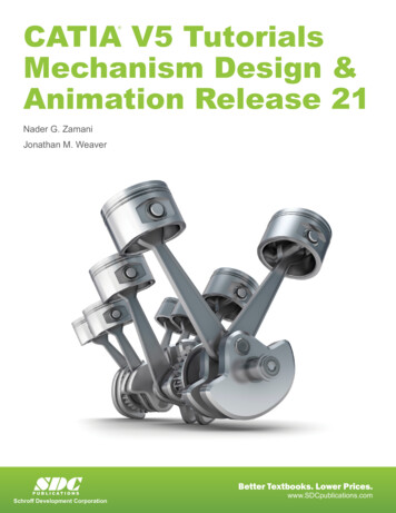
4-14CATIA V5 Tutorials in Mechanism Design and AnimationSelect the New Mechanism button.This leads to another pop up box which allows you to name your mechanism.The default name is Mechanism.1. Accept the default name by pressing OK.Note that the box indicates Unresolved pairs: 4/4.Select the Auto Create button. Then if the Unresolved pairs becomes0/4, things are moving in the right direction.Note that the tree becomes longer by having an Application Branch. The expanded treeis displayed below.
Slider Crank Mechanism4-15The DOF is 1 (if you have dof other than 1, revisit your assembly constraints to makesure they are consistent with those herein, delete your mechanism, then begin this chapteragain). This remaining dof can be thought of as the position of the block along the base,or the rotation of the crank about the base. Since we want to drive the crank at constantangular speed, the latter interpretation is appropriate.Note that because we were careful in creating our assembly constraints consistent withthe desired kinematic joints, the desired joints were created based on the assemblyconstraints created earlier and the Assembly Constraints Conversion icon.All of these joints could also be created directly using the icons in the KinematicsJoints toolbar.In order to animate the mechanism, you need to remove the one degree of freedompresent. This will be achieved by turning Cylindrical.2 (the joint between the base andthe crank) into an Angle driven joint.Note that naming the instances of parts to be the same as the part name makes it easy toidentify the joint between any two parts.Double click on Cylindrical
In CATIA, model four parts named base, crank, conrod, and block as shown below. 1x1x1 cube 1x1 square Diameter 0.5 Length 0.5 Length 10 base Diameter 0.5 Length 0.75 1x1x1 cube Block Diameter 0.5 Diameter 0.5 3.5 Thickness 0.25 crank Diameter 0.7 (4 locations) Diameter 0.5 Diameter 0.5 Length 0.35 6.5 Thickness 0.25 conrod. Slider Crank Mechanism 4-5 Enter the Assembly Design workbench which .File Size: 2MBPage Count: 36