Transcription
CATIA V5 WorkbookRelease 16By:Richard CozzensSouthern Utah UniversitySDCPUBLICATIONSSchroff Development Corporationwww.schroff.comwww.schroff-europe.com
Visit the following websites to learn more about this book:
Lesson 2CopyrightedMaterialNavigating the CATIA V5 EnvironmentIntroductionIn this lesson the user will not complete any one project but will beintroduced to a lot of CATIA V5 tools and concepts. These tools andconcepts are the ones that are required to successfully navigate aroundthe CATIAV5 environment. Gaining a firm understanding of these toolsand concepts will be critical for successfully completing all the otherlessons in this workbook.CopyrightedMaterialFigure 2.1ObjectivesThe main objective of this lesson is to present the necessary tools and concepts for theuser to successfully navigate the CATIA V5 environment. Some things in this lesson arecovered in general terms while others are covered in detail. The user is expected to learnand understand each item as presented in the lesson. Tools and concepts that are brieflyintroduced in this lesson lay the foundation for gaining deeper knowledge in later lessons.Another purpose of the general introduction is to present the user with enoughinformation to promote self-discovery of CATIA V5. The following is a guide to whatthe Review Questions and Practice Exercises will be testing for. You should know thefollowing:-CopyrightedMaterialHow to select any workbench.How to tell which CATIA V5 document is current/active.How the Specification Tree is linked to the geometry.How to modify the Specification Tree.What the compass is and how to use it.The five different methods of selecting entities.How to customize the Welcome to CATIA V5 window.How to modify the CATIA V5 screens (maximize & minimize).How to modify the plane and axis representation.How to toggle the workbench toolbars on and off.How to tear away toolbars and relocate them on the screen.How to recognize when some workbench toolbars are hidden.How to recognize when additional tools are available in a toolbar.How to expand the toolbars with additional tools.How and where the view manipulation tools are.How to use the CATIA V5 Standard Toolbar and its tools.Where the Power Input Mode is and how to use it.Where and how to use CATIA V5s Prompt Zone.The different areas of the CATIA V5 Screen.Gain a general understanding of what CATIA V5 tools are available.CopyrightedMaterial
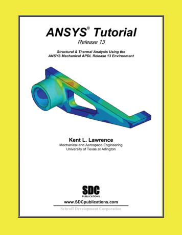
2.2CATIA V5 WorkbookCopyrightedMaterialCATIA V5 Standard Screen LayoutThe following standard screen layout shows you where different tools and toolbars arelocated. The numbers coordinate with the following pages where the tool label is bolded.The tool label is followed by a brief explanation and in some cases, steps on how to useand/or access the tool.Figure 1011161714151819201312021CopyrightedMaterial22The following list of menus is not meant to be a comprehensive definition of every toolon the standard CATIA V5 screen. The purpose is to provide a quick reference andexplanation. If more detailed information is needed and/or required, refer to the CATIAV5 Help menu and/or internet homepage.
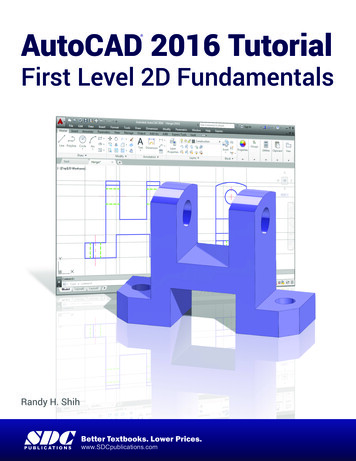
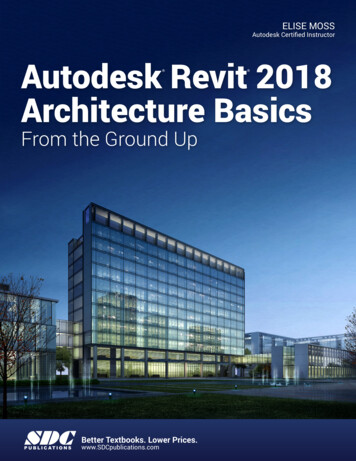
Navigating the CATIA V5 Environment12.3CopyrightedMaterialThe Start MenuThe Start pull down menu gives you access to all of the CATIA V5 Workbenches. Theavailability of the workbenches will depend on the CATIA V5 licenses configuration, theone shown in Figure 2.3 is the Educational Package (ED2) offered through the HEATProgram. The workbenches used in this workbook will be found under MechanicalDesign, Shape, and Digital Mockup Workbench Categories. If you select the arrow tothe right of the Workbench Category the workbenches organized within that category willbe displayed, reference Figure 2.3. Figure 2.3 shows the workbenches organized underthe Mechanical Design Category, the Part Design Workbench is the highlightedworkbench.CopyrightedMaterialThe second section of the Start menu displays the active (open) CATIA V5 documents.Figure 2.3 shows that Part1 and Part2 documents are open, Part2 is the active document.The third section of the Start menu is the most recent active CATIA V5 documents. Thisallows you to quickly open recently active documents. For example, with the optionsshown in Figure 2.3 the Analysis1.CATAnalysis document could be opened by selectingit from this menu rather than opening the browser window and browsing for it.Figure 2.3CopyrightedMaterialCopyrightedMaterial
2.42CATIA V5 WorkbookCopyrightedMaterialThe Current Active CATIA V5 DocumentThis area of the screen displays the name of the current active CATIA V5 document.The active CATIA V5 document shown in Figure 2.2 is the default name(Part1.CATPart) for a CATPart document. For a close up view with document circledreference Figure 2.4. Displaying the name of the currentFigure 2.4document is quite typical of MS Windows compatible software.3The Standard Windows ToolbarCopyrightedMaterialThe Standard Windows toolbar contains your standard MS Windows pull down menus,reference Figure 2.5. There are specific CATIA V5 tools found in the different pulldown menus. The tools youFigure 2.5will be required to use in thisworkbook will be defined in thelesson that they are used in.File MenuAs shown in Figure 2.6, theoptions under the File pull downmenu are very similar to mostother MS Windows programs.Figure 2.6Figure 2.7CopyrightedMaterialEdit MenuAs shown in Figure 2.7 the firstfew options under the Edit pulldown menu is very similar tomost other MS Windowsprograms. The first options arealso available on the StandardToolbar (reference item 16 inFigure 2.2), such as the Undo[Ctrl Z], Repeat [Ctrl Y],Cut [Ctrl X], Copy [Ctrl C]and Paste [Ctrl V].CopyrightedMaterialDelete [Del]: This is one ofthe numerous methodsCATIA V5 allows for youto delete selected items.Update [Ctrl U]: The Update tool allows you to force the document to be updated.There is a toggle in Tools Options that allows CATIA V5 to update automatically.When the Update tool is dimmed there is no update to be performed.
Navigating the CATIA V5 Environment2.5CopyrightedMaterialSearch [Crtl F]: The Search tool allows you to search the document for almost anytype of variable. Selecting this tool brings up a Search window that allows you toinput specific parameters to help narrow the search.Links: The Links tool allows you to view all documents that are linked to the currentdocument. This is a very useful tool when dealing with a multitude of linkeddocuments such as assemblies.Properties [Alt Enter]: The Properties tool allows you to view and/or modify theproperties of the selected element. This tool is also available contextually (selectingthe element and then selecting the right mouse button).Scan or Define In Work Object: This tool allows you to review how the part in thedocument was created, step-by-step. This is a powerful design and review tool that iscovered in depth in the Part Design Lesson.CopyrightedMaterialView MenuMost of the tools in this pull down menu have tofunctions dealing with the visualization of the CATIA V5document. Many of the tools can be accessed from thebottom toolbar, quick keys and contextually (right mouseclick). Figure 2.8 displays the tools available in the Viewpull down menu. The following is a brief description ofeach tool found in the View Pull Down Menu.Figure 2.8Toolbars: Toolbars allows you to toggle additionaltoolbars on and off. If a particular tool gets closedyou can use this tool to turn it back on. This iscovered in more detail later in this lesson.CopyrightedMaterialCommand List : This tool brings up the CommandList window that lists all the CATIA V5 commands.For example if you wanted to create a Point and couldnot find the Point tool, you could go to View Command List and browse for the Point, selectPoint and enter the appropriate values for X, Y and Z.Geometry: This is a toggle tool that places thegeometry into hide/show (visible/not visible).CopyrightedMaterial
2.6CATIA V5 WorkbookCopyrightedMaterialSpecification: This is a toggle tool that places the Specification Tree into hide/show.Notice that there is also a quick key for this, F3.Compass: This is a toggle tool that places the compass into hide/show. The compassis area 5 in Figure 2.2.Reset Compass: This tool allows you to reset the compass back to its originallocation and orientation. For details, reference area 5 in Figure 2.2.Tree Expansion: This tool allows you to expand theSpecification Tree automatically, at specified levels, orcontract the Specification Tree. Selecting this optionwill bring up a window similar to what is shown inFigure 2.9.Figure 2.9CopyrightedMaterialSpecification Overview: This tool allows you to zoomin or out quickly on the Specification Tree.Geometry Overview: This tool allowsyou to zoom in or out quickly on thegeometry in the workspace. Selectingthis tool brings up the Overview ongeometry window as shown in Figure2.10. Notice that the part showing in theworkspace is the same as what is shownin the resizable window. As you changethe size and/or location of the resizablewindow the geometry in the workspacechanges accordingly.Figure 2.10Resizable windowdefining theviewable geometryCopyrightedMaterialFit All In: This tool allows you toquickly zoom out so that all the geometryis viewable on the screen. This tool isalso located on the bottom View Toolbar,area 15 in Figure 2.2.Zoom Area: This tool allows you toquickly zoom in on a particular area ofgeometry. Select the tool and then usingthe mouse select the first corner of arectangle that encompasses the area you want to zoom in on. Drag the cursor to thesecond point of the rectangle and release the mouse button. The workspace windowwill update to the area you just defined.CopyrightedMaterialZoom In Out: This tool allows you to quickly zoom out. This tool is also located onthe bottom View Toolbar. This is covered in detail in Lesson 4.
Navigating the CATIA V5 Environment2.7CopyrightedMaterialPan: This tool allows you to move the geometry around on the screen. It does notchange the location relative to the origin, just your view of the workspace. This toolis also located on the bottom View Toolbar. This is covered in detail in Lesson 4.Rotate: This tool allows you to rotate the part. This tool is also located on thebottom View Toolbar. This is covered in detail in Lesson 4.Modify: This tool provides some additional ways tomodify your views, some are duplicate methods, referenceFigure 2.11. Selecting the Modify option brings up awindow similar to the one shown in Figure 2.11. The firstfour options will be covered in later lessons. PreviousView and Next View allow you to step back and forththrough the all the views still in memory. The Look At toolallows you to create a rectangle around the area you want tolook at, similar to the Zoom Area tool. The Turn Headtool allows you to pivot your view from the center ofrotation. This tool is hard to control and it is easy to loosesight of your geometry, if you experience this select the FitAll In. The Zoom In and Zoom Out tools are duplicates ofthe tools already discussed. The Normal View tool allowsyou to select a planner surface and CATIA V5 will rotateyour view normal (perpendicular) to the selected plannersurface.Figure 2.11CopyrightedMaterialNamed Views: Selecting this toolwill bring up a window similar to theone shown in Figure 2.12. All thedefault views are duplicates of viewsprovided in the View toolbar, area 15in Figure 2.2. The real power of thistool is the capability to create and saveyour own custom view as shown inFigure 2.12. To create your owncustom view zoom and orient thegeometry the way you want to savethe view. Select View NamedViews, this will bring up the NamedViews Window. Select the Addbutton. In the input window type thename of your customized view. Selectthe Apply button. Now any time youwant to jump to this view select View Named Views and select the viewyou just created and named. CATIAV5 will update to that view.CopyrightedMaterialFigure 2.12CopyrightedMaterial
2.8CATIA V5 WorkbookFigure 2.13CopyrightedMaterialFigure 2.14CopyrightedMaterialRender Style: Selecting the Render Style tool willbring up a window similar to the one shown in Figure2.13. The tools located in the first section of thiswindow are duplicates of the tools found in the Viewtoolbar, reference area 15 in Figure 2.2. Selecting theCustomize View will bring up a window similar to theone shown in Figure 2.14. This particular tool allowsyou to mix and match different view properties.Review the options; apply them to some geometry soyou are comfortable with the different options. Toapply your customized view, select the OK button.The geometry in the workspace can be represented using the Perspective view or theParallel view. The Perspective view shows the geometry as the human eye wouldsee it. The depth of the geometry reseeds back to a vanishing point. The Parallelview shows the depth of the geometry true length.CopyrightedMaterialNavigation Mode: Selecting the Navigation Mode willbring up a menu similar to the one shown in Figure 2.15.These options will be covered in detail in later lessons.Figure 2.15Lighting: This tool allows you to modify the lighteffect on the workspace. This tool will be covered inmore detail in the DMU Workbench Lessons.CopyrightedMaterialDepth Effect: This tool allows you to modify and visualize the geometry at differentthicknesses. This tool will be covered in more detail in the DMU WorkbenchLessons.Ground: This tool allows you to create and modify ground representation for thegeometry in the workspace. This tool will be covered in more detail in the DMUWorkbench Lessons.
Navigating the CATIA V5 Environment2.9CopyrightedMaterialMagnifier: This tool allows you to zoom into a specific area of the geometry. Thistool will be covered in more detail in the DMU Workbench Lessons.Hide/Show: This tool is a duplicate of the Hide/Show t
2.4 CATIA V5 Workbook Figure 2.7 Figure 2.4 Figure 2.5 Figure 2.6 The Current Active CATIA V5 Document This area of the screen displays the name of the current active CATIA V5 document. The active CATIA V5 document shown in Figure 2.2 is the default name (Part1.CATPart) for a CATPart document. For a close up view with document circledFile Size: 823KBPage Count: 42