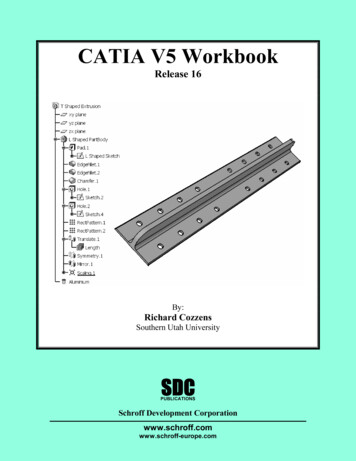
Transcription
CETPA INFOTECH PVT. LTD.CURRICULUM OF CATIACATIA V5 Foundation TrainingINTRODUCTION OF DESIGN CONCEPT ANDPROCEDURE Detailed Concept Of CADNeed & Importance Of CADOverview About Actual Designing In Industries,Fundamentals Of Design And Its ImplementationMethodsAll Characteristics Of Catia To User FriendlyAtmosphereSuperiority Of Catia With Its Use And Demand --------------------------TAKING THE CATIA V5 TOUR Introduction To Catia V5 Version.System RequirementsStarting Catia Version V5The Workbench ConceptWorkbenchesAdjusting The Catia InterfaceCreating And Managing WorkspaceMenu And ToolbarsStarting New DrawingFinding ToolsSelecting/Moving Objects With MouseThe Object/Action And Action/Object ApproachesWorking With PlanesGraphic Properties ToolbarChanging The Graphic PropertiesChanging The Interface From 3d Modeling To 2dSketching And Vice-VersaUses & Description About Specification Tree,Navigation Compass.View Toolbar As A Common Toolbar For All TheInterface.Documentation ------------------------SKETCHER Introduction Of Drafting And Its ConceptEntering/Exiting The Sketcher WorkbenchCoordinate SystemsProfile Creation Tools For Creating 2D SketchModifying The Sketch Created (If Error Is There)Open Profiles And Its LimitationsCATIA V5 Foundation Training Tools For Changing Visualization And Orientation OfSketchUses Of Constrains Tools For Making FullyConstrained SketchOperation Tools For Reducing Work And EasyDrawings.Creating Basic SketchPositioned SketchingCommands Such As Lines, Circle EtcPre-Defined ProfilesUser-Defined ProfilesSetting UnitsConstruction GeometryConstraining The SketchDifference Between Dimensional Constraints AndGeometrical ConstraintsGeometry & Constraints Management (GeometricAnd Dimensional)Explanation Of Fully Constrained SketchesSketcher Re-LimitationsTrim OptionsQuick Trim OptionsMirroring An ObjectPlacing/Making An Object In A Symmetrical PositionTranslation, Rotation And Scaling An ObjectOffset And Offset Propagation ModesProjecting A 3D ElementIsolating Projecting ElementsSketch Analysis Window And Sketch AnalysisQuick Geometry -----------------------BASIC FEATURES OF PART DESIGNING Concept Of 3D And Part Design TerminologySelecting Sketch To Convert It Into VolumetricDesignConcept Of Volumetric Designing With Respect ToIndustriesCreating Base FeaturesSelecting A Base Feature And Modifying ThemCreating Volume In Linear Direction (Pad)Creating A Cavity In Volume In Linear Direction(Pocket)Limitations Of Pad And Pocket CommandRestrictions For Pad/Pocket Profile Sketches1 Page
Restrictions For Pad/Pocket Profile SketchesCreating Multi-Pads/PocketsCreation Of Axis At Required PlaceDimensioning An Axis For Appropriate WorkCreation Of Volume In Circular Shape (Shaft)Removal Of Volume In Circular Shape (Groove)Restrictions Of Revolved FeaturesCreation/Removal Of Volume On Pre-Defined Path(Rib/Slot)Creation Of Hole Using Positioning SketchHole Creation Using Pre-Defined ReferencesIntroduction To StiffenersCreating A New Volume Using Two DifferentSketches (Solid Combine)Volume Creation Using Multiple Sketches WithMultiple OptionsCreating Cavity Using Multiple SketchesDRESS-UP FEATURES OF PART DESIGNING Creating Curves Edges Using The MultipleReferences & bleReferencesShell Creation In A Body.Advance Shell Creation In A Body With DifferentDimensions Of Different SidesAdding Thickness To An Already CreatedSide/VolumeRemoval Of Extra Faces In A BodyReplacing The Face In A Body To Another BodyCreating Thread And Taps In Cylindrical BodyDUPLICATING FEATURES OF PART DESIGNING Mirroring Single/Multiple Feature With Respect ToPlaneExplode Mirrored Object/Objects For Further UsePatterns And Its ImportanceUse Of Standard Pattern Styles (RectangularPattern, Circular Pattern)Creating A New Pattern On User Defined InstancesNeed Of Exploding The Pattern For Editing AndAdditional UsageKeeping The Specifications To Create A DefinedPatterns Translating An Object/Body From Its OriginalPositionRotate An Object/Body From Its Position WithRespect To AxisPlacing The Body/Object In A Symmetrical PositionWith Respect To PlaneChange The Scale Of The Body By Selecting DifferentFaces Or With Axis SystemImportance Of Axis To Axis System And Its Use InGeometryEDITING FEATURES OF PART DESIGNING Investigating The ModelConcept Of Parent-Child RelationshipsRedefining Parameters Of Previously CreatedFeaturesChanging The Order Of Any Feature In ASpecification TreeHiding And Un-Hiding The Sketches/Features/BodyDeactivating/Activating Of Features As PerRequirementsUse Of Defining Any Feature In Work ObjectResolving The Failures Of The Features/BodyADDITIONAL FEATURES OF PART DESIGNING Importance & Use Of Reference GeometryCreating Points In A 3d Space With The Help OfAvailable References.Creating/Introducing Line In 3d Space WithReferencesUses Of Line Created In A 3d SpaceIntroduction To Concept Of PlanesCreation Of New Planes In A GeometryOptions Available For Creating Planes In Free BodyMulti-Body And Its UsesInserting A New Body In Previously Created BodyConcept Of Boolean Operations And Use Of BooleanOperation In BodyBoolean Operation: AddBoolean Operation: RemoveBoolean Operation: IntersectMeasure ToolsUse Of Graphic Properties Toolbar For MakingVisualization ----------------------2 Page
ASSEMBLY MODELING & PRODUCTMODELING What Is An AssemblyDefining A New Assembly DocumentAssigning Properties To The ProductTools Used For Creating Product StructureUse Of Compass In AssemblyImporting Existing Components In A NewAssembly Snapping Components Editing A Previously Created Part/Product InAssembly Features Exploding A Constrained Assembly Reordering Product Structure Reusing A Component (Copy/Paste) Components Catalogue Degree Of Freedom In The Assembly Constraint Creation Analyzing Created Constraints Assembly Features Making Pattern Of Any Object Using Existing Assemblies To Create A ProductStructure Use An Object With Respect To Pattern Scenes Saving An Assembly Document Opening/Loading An -----------------------DRAFTING Introduction Of DraftingNeed & Importance Of DraftingStarting The Drafting WorkbenchDefining The Sheet & Sizes Adjusting Of Drawing Sheet According ToObject/AssemblyTypes Of ProjectionUsing Predefined Drafting StylesScaling The Drafted ViewGENERATIVE DRAFTING IntroductionTaking Projection Of Front View On SheetGenerating Different Views Such As Top ViewEtcDifference Between Primary And SecondaryViewModifying An Existing ViewGenerative DimensionsBalloon Generation For Drafting Of AssemblyINTERACTIVE DRAFTING IntroductionView PlanesCreating Multiple Projections Of Different ViewsCreating Views For Folding LinesShow/Hide Hidden Lines, Centre Line, Axis Line,Thread EtcModifying An Existing ViewCreating -------------------------DATA EXCHANGE Converting Files For TransferringConverting Into IGES, STEP, PARASOLID Etc.Convert Into Jpeg, Mpeg, Tiff, Pdf Files3 Page
CATIA V5 Professional TrainingWIREFRAME & SURFACE DESIGN Introduction To Surface DesignImportance Of SurfaceProcess Of Surface DesigningEntering The WorkbenchGenerative Surface Design ProcessDifference Between Open Bodies &Connected Bodies3D Wireframe GeometryPoints & Its RoleCreating Multiple Points On A CurveLines In Free BodyLine & Axis LinesCreating Line & Axis Line In Free SpaceCreating PolylinesRole Of Planes In SpaceCreating New Plane With New ReferencesCreating A Set Of Planes In An OrderCreating Free Body CurveConnecting Different ace GeometryCreating Surface Using Multiple SectionsCreating A Blend SurfaceCreating A Swept SurfaceManipulating The Swept Surface WithReference Surface Option CATIA V5 Professional TrainingExtracting An Edge From A SurfaceExtracting Face Of Different SurfacesCreating A Solid From SurfaceSplitting Object/Body With SurfaceDatum FeaturesThickening A SurfaceClosing A Surface In To Volumetric BodyEditing Created ElementsChecking Connections Between SurfacesChecking Connections Between CurvesUpdating Object/PartDynamic Sectioning -------------------SHEETMETAL DESIGN Introduction To Sheetmetal DesignGenerative Sheetmetal DesignEntering The Sheetmetal WorkbenchProcess Of Sheetmetal DesigningSheetmetal Parameters & Its ImportanceSheetmetal WallTypes Of WallsProfile Based WallExtruded WallCreating A Multi-Connected Profile WallsAdditional Types Of WallsTangent WallsCreation Of Walls On The EdgeWhat Is BendBending A Flat Sheet4 Page
Creating A Swept Surface With GuideCurvesSwept Surface Including SpineManipulation Of Swept Surface WithPosition ProfileIntroduction To SpineLine SweepCircle SweepAdaptive Swept SurfaceJoining Different SurfacesTrimming Created ElementsFilletsTransformation Features In SurfaceGeometryExtrapolating SurfaceDisassembling A SurfaceHealing Of SurfaceRestoring A Surface Folding & Unfolding Of The FacesCreating Relief On The CornerFlange & Its TypesFeatures Of SheetmetalCreating Holes In SheetStamp & Its Role In IndustryStandard StampsOpening Faces Of StampTranslating Created Sheet With ParametersRotating Sheetmetal PartsPattern And Its TypesMirroring The FeaturesUnfolded ViewHEAD OFFICE:200 Purwavali , 2nd Floor, (Opp. Railway Ticket Agency), Railway Road , Ganeshpur,Roorkee – 247667, Ph.No.: 09219602769, 01332-270218 Fax - 1332 – 274960CORPORATE OFFICE: D-58, Sector-2, Near Red FM. Noida -201301, Uttar PradeshContact Us: 91-9212172602 , 0120-4535353thBRANCH OFFICE:401 A, 4 Floor, Lekhraj Khazana, Faizabad Road, Indira Nagar,Lucknow-220616 (U.P.) Ph. No: 91-522-6590802, 91-9258017974BRANCH OFFICE:105, Mohit Vihar, Near Kamla Palace, GMS Road, Dehradun-248001, UKContact: 91-9219602771, 0135-6006070Toll Free- 1800-8333-999 (from any network)5 Page
Convert Into Jpeg, Mpeg, Tiff, Pdf Files . 4 P a g e CATIA V5 Professional Training WIREFRAME & SURFACE DESIGN Introduction To Surface Design Importance Of Surface Process Of Surface Designing Entering The Workbench Generative Surface Design Process Difference Between Open Bodies & Connected Bodies 3D Wireframe Geometry Points & Its Role Creating Multiple Points On A