Transcription
Driven Pile TypesPDCA 2015 Professor Driven Pile InstitutePatrick HanniganGRL Engineers, Inc.
Common Driven Pile TypesSteelPipeTimberSteelHPrecast CompositeConcrete
Driven PileClassificationChartDriven Bearing tensionCompositePS Conc.– H-pilePS Conc.- PipePipe –H-pileOpen EndClosed EndUn-FilledConcreteFilledCased, Cast-in-PlaceReinforcedPost- JointedtensionNonJointedCylinderDriven w/ MandrelPipeCasedShellCasedDriven w/o MandrelPipeMonotubeTapertube
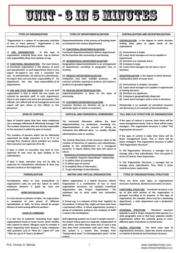
Timber Pile OverviewTYPICAL LENGHTS:15 to 75 feet – Southern Pile15 to 120 feet – Douglas FirMATERIALSPECIFICATIONS:ASTM D-25AWPA-UC4A, 4B, 4C, 5B, and 5CASD:Typical Design Stress: 0.8 to 1.2 ksi(based on pile toe area)Design Load: 20 to 100 kips (10 to 50 tons)Driving Stress: 3 x Design Stress (3 ksi /-)LRFD:Factored Load: 50 to 120 kips (25 to 60 tons)Driving Stress: 1.15 x Fco (1.4 ksi /-)ADVANTAGES:Comparatively low initial cost.Easy to handle.Permanently submerged piles resistant to decay.DISADVANTAGES:Difficult to splice.Vulnerable to damage in hard driving at pile head and pile toe.Vulnerable to decay if untreated and intermittently submerged.REMARKS:Best suited for friction pile in granular soil.
Timber Piles
Timber Piles
Timber Pile - Toe Protection
Timber Pile - Banding
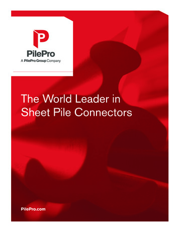
H-Pile OverviewTYPICAL LENGHTS:15 to 200 feetMATERIALSPECIFICATIONS:ASTM A-572, A-588, or A-690(A-572 Grade 50 is standard)ASD:Typical Design Stress: a: 0.25 to 0.33 FY(12.5 to 16.5 ksi)Design Load: a As: 132 to 993 kips (HP 8x36 to HP 18x204)Driving Stress: 0.90 FY (45.0 ksi)LRFD:Factored Load: 310 to 1800 kipsDriving Stress: da FY 0.90 FY( FY 50, 60 ksi )(45.0 ksi)ADVANTAGES:Available in various sizes, sections and lengths.Easy to splice.High capacities possible.Low soil displacements.Pile toe protection may assist in penetrating harder layers or somesmall obstructions.DISADVANTAGES:Vulnerable to corrosion where exposed.HP sections can be damaged or deflected by major obstructions.REMARKS:Best suited for toe bearing on rock.HP sections tend to “run” in granular deposits.
H-Piles
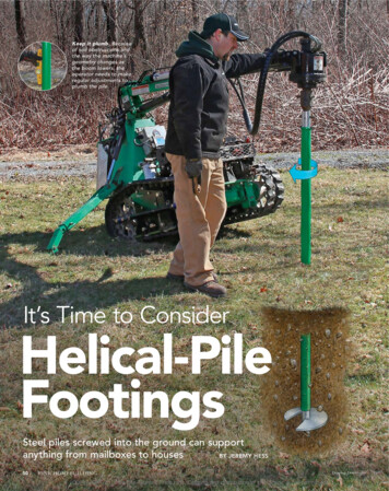
New Larger H-Pile Sections18 in.HP 18 x 204, As 60.0 in2
H-Pile - Toe Protection
H-Pile - SplicesFull PenetrationGroove WeldH-pile Splicer
H-Pile - Splices
Pipe Pile OverviewTYPICALLENGHTS:15 to 200 feetMATERIALSPECIFICATIONS:ASTM A-252, Grade 2 or 3 (FY 35, 45 ksi), API 5L (FY 42 to 80 ksi )ACI 318 – for concrete (if filled)ASTM A-572 – for core (if used)ASD:Design Stress: a 0.25 to 0.33 FY (on steel) 0.40 f’c (on concrete)Design Load: 100 to 3,400 kipsDriving Stress: 0.90 FY (31.5 to 40.5 ksi) or (37.8 to 72.0 ksi)LRFD:Factored Load: 100 to 1250 kips (closed end) with concrete fill365 to 4,000 kips (open end) without concrete fillDriving Stress: da FY 0.90 FY (31.5 to 72.0 ksi)ADVANTAGES:Available in various lengths, diameters, wall thicknesses and strengths.High capacities possible.Easy to splice.Closed end can be internally inspected after driving.Open end pipe can be cleaned out and driven deeper.Open end pipe has low soil displacements.DISADVANTAGES:Vulnerable to corrosion.Soil displacement for large, closed end pipeREMARKS:High bending resistance on unsupported length.
Typical Pipe Pile Closure PlateFilletWeldFlat Closure Plate
Conical Pipe Pile Tip
Outside Cutting Shoe
Inside Cutting Shoe
Large Diameter Open End Pipe
Spin Fin Pile
Pipe Pile - SplicingFull PenetrationGroove Weld
Pipe Pile - SplicingFriction Splicer
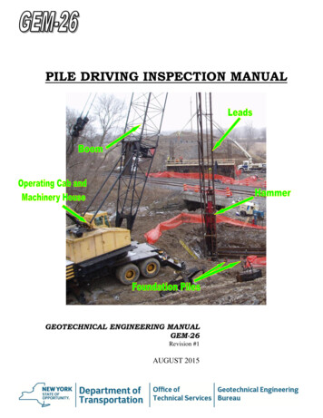
Monotube Pile OverviewTYPICAL LENGHTS:15 to 100 feetMATERIALSPECIFICATIONS:SAE-1010 - for steel( FY 50.0 ksi )ACI 318 - for concreteASD:Typical Design Stress: a 0.25 FY (on steel) 0.40 f’c (on concrete)Design Load: 100 to 300 kipsDriving Stress: 0.90 FY (45.0 ksi)LRFD:Factored Load: 100 to 450 kipsDriving Stress: 0.90 FY (45.0 ksi)ADVANTAGES:Can be inspected after driving.High capacity for relatively shorter lengths.Tapered pile section provides high resistance in granular soils.Reduced concrete fill volume in tapered pile section.DISADVANTAGES:Potential soil displacement effects.REMARKS:Best suited for friction pile of medium length.
Monotube PilesWall thicknesses:0.15 to 0.24 inches(3 to 9 gage)Uniform extensionswith one crimped endInitial taper section:10 to 75 ft longPile toe: 8 or 8.5inch diameter
Monotube SplicingCut V Notches at 90 Fillet WeldGrind V Notches
Tapertube Pile OverviewTYPICAL LENGHTS:50 to 150 feetMATERIALSPECIFICATIONS:ASTM A-252, Grade 3 ( FY 45.0 ksi )ACI 318 – for concreteASD:Typical Design Stress: a 0.25 FY (on steel) 0.40 f’c (on concrete)Design Load: 200 to 420 kipsDriving Stress: 0.90 FY (40.5 ksi)LRFD:Factored Load: 200 to 850 kipsDriving Stress: 0.90 FY (40.5 ksi)ADVANTAGES:Can be internally inspected after driving.High capacity for relatively shorter lengths.Tapered pile section provides high resistance in granular soils.Reduced concrete fill volume in tapered pile section.DISADVANTAGES:Potential soil displacement effects.REMARKS:Best suited for friction pile in granular soils.
Tapertube PilesStandard pipe pileextensionsTaper wall thicknesses:0.25 to 0.438 inchesTaper section:15 to 30 ft long,flat sided polygonPile toe: 8, 10, 12, or14 inch diameter
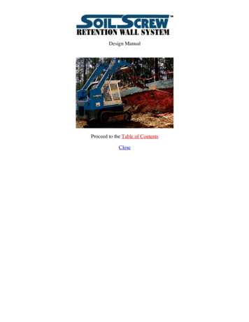
Prestressed Concrete OverviewTYPICAL LENGHTS:30 to 150 feetMATERIALSPECIFICATIONS:ACI 318 – for concreteASTM A-82, A-615, A-722, and A-884 for reinforcing steel.ASTM A-416, A-421, and A-882 for prestressing.ASD:Design Stress: 0.33 f’c – 0.27 fpe (on gross concrete area)Design Load: 90 to 1000 kipsDriving Stress: 0.85 f’c – fpe (in compression)3 f’c fpe (in tension, f’c in psi)LRFD:Factored Load: 350 to 2,200 kips on solid sections.1,500 to 3,000 kips on spun cast cylinder piles.Driving Stress: 0.85 f’c – fpe (in compression)3 f’c fpe (in tension, f’c in psi)ADVANTAGES:High load capacity.Corrosion resistance obtainable.Hard driving possible.DISADVANTAGES:Can have relatively high breakage rate.Potential soil displacement effects from large sections.Difficult to splice when insufficient length ordered.REMARKS:Cylinder piles well suited for bending resistance.
Prestressed Concrete
Prestressed Concrete DetailsTypicalSizes10 – 20inch20 – 36inch10 – 24inch11 – 18inch void11 – 15inch void
ConcretePileSplices
KIE-LOCKMechanicalSplice
EpoxyDowelSplice
Prestressed Concrete - Cutoff
Spun Cast ConcreteCylinder Piles
Spun Cast ConcreteCylinder PilesPile PropertiesHigh strength concrete, f’c 7 ksi, fpe 1.2 ksi16 ft long pile segments (typical)Segments combined and post-tensionedTypical Sizes36, 42, 48, 54, & 66 inch O.D.5 & 6 inch wallTypical Design Loads250 to 800 tons
ICP Spun Cast PilePile PropertiesHigh strength concretef’c 10 ksi, fpe 1 ksi20 to 120 ft long segmentsWelded pile spliceTypical Pile Sizes9.8 to 47.2 inch O.D.2.2 to 5.9 inch wallTypical Design Loads80 to 1100 tons
ICP Spun Cast PileWelded Splice
Composite Piles - OverviewTYPICAL LENGHTS:50 to 200 feet.MATERIALSPECIFICATIONS:ASTM A-572 for H-pile sectionsASTM A-252 for pipe pile sectionsACI 318 – for concreteASTM D25 for timber sectionsMAXIMUMSTRESSESS:Typical Design Stress: Depends on pile materialsDriving Stress: Depends on pile materialsTYPICALDESIGN LOADS:30 to 200 tonsADVANTAGES:May solve unusual design or installation problems.High capacity may be possible depending on pile materials.May reduce foundation costs.DISADVANTAGES:May be difficult to attain god joint between pile materials.REMARKS:Weakest pile material controls allowable stresses and capacity.
Composite PilesPipe – H-pileConcrete – H-pile
Composite PilesCorrugated Shell - TimberPipe - Concrete
Other Pile SelectionConsiderations Site and access considerations. Subsurface considerations. Pile shape considerations. Drivability considerations.
Site Considerationson Pile SelectionImpact of vibrations on nearby structures.Remote areas may restrict equipment size.Local availability of pile materials and capabilities of localcontractors.Waterborne operations may dictate use of shorter pilesections.Steep terrain may make use of certain pile equipmentcostly or impossible.
Subsurface Effects on Pile SelectionTypical ProblemRecommendationBoulders over Bearing StratumUse Heavy Low Displacement PileWith Shoe. Include ContingentPredrilling Item in Contract.Loose Cohesionless SoilUse Tapered Pile to DevelopMaximum Shaft Resistance.Negative Shaft ResistanceAvoid Batter Piles. Use Smooth SteelPile to Minimize Drag Load or UseBitumen Coating or Plastic Wrap. CouldAlso Use Higher Design Stress.Deep Soft ClayUse Rough Concrete Piles to IncreaseAdhesion and Rate of Pore WaterDissipation.
Subsurface Effects on Pile SelectionTypical ProblemRecommendationArtesian PressureHydrostatic Pressure May CauseCollapse of Mandrel Driven Shell Pilesand Thin Wall Pipe. Pile HeaveCommon on Closed End Pipe.ScourAdequate Pile Capacity Should beDeveloped Below Scour Depth(Design Load x SF). Tapered PileShould Be Avoided Unless TaperExtends Below Scour Depth.Coarse Gravel DepositsUse Prestressed Concrete Piles WhereHard Driving is Expected.
Pile Shape Effects on Pile SelectionShapeCharacteristicDisplacementPile TypesPlacement EffectsClosed EndSteel PipeIncrease Lateral Ground Stress.Densify Cohesionless Soils.PrestressedConcreteTemporarily Remolds andWeakens Cohesive Soils.Setup Time for Large Pile Groupsin Sensitive Clays May Be Up ToSix Months.
Pile Shape Effects on Pile SelectionShapeCharacteristicPile TypesLow DisplacementSteel H-pileOpen EndSteel PipePlacement EffectsMinimal Disturbance to Soil.Not Recommended for FrictionPiles in Coarse Granular Soils.Piles Often Have Low DrivingResistances in These DepositsMaking Field Capacity VerificationDifficult Resulting in ExcessivePile Lengths Installed.
Pile Shape Effects on Pile SelectionShapeCharacteristicPile TypesTaperedTimberMonotubeTapertubeThin WallShellsPlacement EffectsIncreased Densification of Soil.High Capacity for Short PenetrationDepth in Granular Soils.
Final Pile Selection Each type has advantages and disadvantages. Several pile types or sections may meet theproject design requirements. All candidate pile types should be carriedforward in the design process. Final pile selection should be based on themost economical pile section meeting all thedesign requirements.
Questions? ? ?
ASTM A-572, A-588, or A-690 ( F Y 50, 60 ksi ) (A-572 Grade 50 is standard) ASD: Typical Design Stress: a: 0.25 to 0.33 F Y (12.5 to 16.5 ksi) Design Load: a A s: 132 to 993 kips (HP 8x36 to HP 18x204) Driving Stress: 0.90 F Y (45.0 ksi) LRFD: Factored Load: 310 to 1800 kips Driving Stress: da F Y 0.90 F Y (45.0 ksi) ADVANTAGES: Available in various sizes, sections and lengths. Easy to .