Transcription
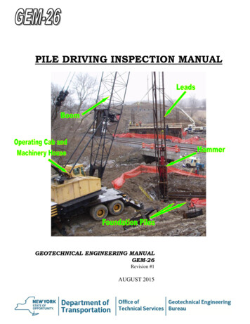
Studia Geotechnica et Mechanica, Vol. 37, No. 4, 2015DOI: 10.1515/sgem-2015-0048PILE LOAD CAPACITY – CALCULATION METHODSBOGUMIŁ WRANACivil Engineering Department, Institute of Structures Mechanics, Soil-Structure-Interaction Branch,Cracow University of Technology, Warszawska 24, 31-155 Kraków, Poland,e-mail: wrana@limba.wil.pk.edu.plAbstract: The article is a review of the current problems of the foundation pile capacity calculations. The article considers the mainprinciples of pile capacity calculations presented in Eurocode 7 and other methods with adequate explanations. Two main methodsare presented: α – method used to calculate the short-term load capacity of piles in cohesive soils and β – method used to calculatethe long- term load capacity of piles in both cohesive and cohesionless soils. Moreover, methods based on cone CPTu result are presented as well as the pile capacity problem based on static tests.Key words: pile load capacity calculation, Eurocode 7, α – method and β – method, direct methods based on CPTu data1. INTRODUCTIONThe pile load capacity on compression (Fig. 1a–1c)is considered in the article, in particular the sufficientcompressing resistance case (Fig. 1a).Piles can be either driven or cast in place. Piledriving is achieved by: impact dynamic forces fromhydraulic and diesel hammers; vibration or jacking.Concrete and steel piles are most common. Drivenpiles which tend to displace a large amount of soil dueto the driving process are called full-displacementpiles. Cast-in-place (or bored) piles do not cause anysoil displacement, therefore, they are non-displacement piles.Piles may be loaded axially and/or transversely.The limit states necessary to be considered in thedesign of piles are the following (EN-1997-1,§7.2.(1)P): Bearing resistance failure of the pile foundation, Insufficient compression resistance of the pile(Fig. 1a), Uplift or insufficient tensile resistance of the pile(Fig. 1d), Failure in the ground due to transverse loading(Fig. 1f), Structural failure of the pile in compression (Fig.1b), tension (Fig. 1e), bending (Fig. 1g), buckling(Fig. 1c) or shear (Fig. 1h), Combined failure in the ground, in the pile foundation and in the structure, Excessive settlement, heave or lateral movement, Loss of overall stability, Unacceptable vibrations.Fig. 1. Piles load capacity:(a)–(c) on compression, (d), e) on tension,(f)–(h) on transverse loadingFigure 2a shows the following main parametersused in the pile capacity problem: s(Q) – load-settlement top pile data recorded in thein-situ test on compression, sk – characteristic settlement, generally calculatedusing the assumption on soil behavior as: semiinfinite elastic, isotropic and homogenous area(Boussinesq theory), which gives such larger settlement than the measured one,UnauthenticatedDownload Date 3/8/16 7:28 PM
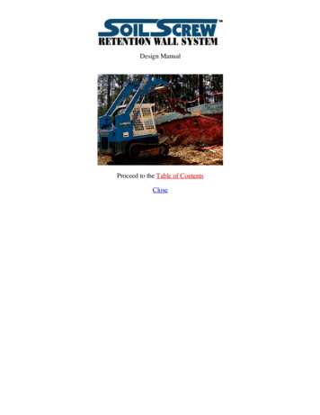
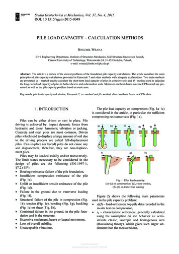
84B. WRANA Rc;d – design resistance as the capacity parametersdetermined from designing standards, consideredin the present article, Rtest – in-situ static test result on top pile, Qlim – limit resistance defined as rapid settlementoccurs under sustained or slight increase of the applied load – the pile plunges.Ration of Qlim/Rc;d γt presents the total safetyfactor.(1) The results of static load tests, which have beendemonstrated by means of calculations or otherwise, to be consistent with other relevant experience,(2) Empirical or analytical calculation methods whosevalidity has been demonstrated by static load testsin comparable situations,(3) The results of dynamic load tests whose validityhas been demonstrated by static load tests in comparable situations,(4) The observed performance of a comparable pilesfoundation, provided that this approach is supported by the results of site investigation andground testing.Equilibrium equationThe equilibrium equation to be satisfied in the ultimate limit state design of axially loaded piles incompression isFc; d Rc; d ,(1)where Fc;d is the design axial compression load andRc;d is the pile compressive design resistance.Fig. 2a. Capacity parameters:Rc;d – design resistance, Rtest – static test result,Qlim – limit resistance, s(Q) – load-settlement curvefrom top pile measurement sk – characteristic settlementFigure 2b shows typical load/settlement curves forcompressive load of the shaft Qs and the base Qb loadcapacity and the total load capacity Qt characteristicdepending on soil layers: (a) for friction pile and(b) for end-bearing pile.Design axial loadThe design axial compressive load Fc;d is obtainedby multiplying the representative permanent and variable loads, G and Q by the corresponding partial action factors γG and γQFc; d γ G Grep γ Q Qrep .(2)The two sets of recommended partial factors onactions and the effects of actions are provided in Table A3 of Annex A of EN 1997-1.Characteristic pile resistanceFig. 2b. Typical load/settlement curves for compressive load tests:(a) friction pile; (b) end-bearing pile2. APPROACHES OF PILE DESIGNACC. TO EN-1997EN 1997-1 §7.4(1)P states that the design of pilesshall be based on one of the following approaches:Eurocode 7 describes three procedures for obtaining the characteristic compressive resistance Rc,k ofa pile:(a) Directly from static pile load tests with coefficientξ1 and ξ2 for n pile load tests, given in Table A.9of EN 1997-1 Annex A,(b) By calculation from profiles of ground test results orby calculation from ground parameters with coefficient given in Table A.10 of EN 1997-1 Annex A,(c) Directly from dynamic pile load tests with coefficientgiven in Table A.11 of EN 1997-1 Annex A.In the case of procedures (a) and (b) Eurocode 7provides correlation factors to convert the measuredpile resistances or pile resistances calculated fromprofiles of test results into characteristic resistances.UnauthenticatedDownload Date 3/8/16 7:28 PM
Pile load capacity – calculation methodsCase (c) is referred to as the alternative procedure inthe Note to EN 1997-1 §7.6.2.3(8), even though it isthe most common method in some countries.Part 2 of EN 1997 includes the following Annexeswith methods to calculate the compressive resistance,Rc,cal of a single pile from profiles of ground test results:(a) D.6 Example to determine Rc;cal based on conepenetration resistance: relating the pile’s unit baseresistances qb at different normalised pile settlements, s/D, and the shaft resistance qs to averagecone penetration resistance qc values. The valuesin Tables D.3 and D.4 are used to calculate the pilebase and shaft resistances in the pile.(b) D.7 Example to determine Rc;cal base on maximumbase resistance and shaft resistance from the qc values obtained from an electrical CPT.(c) E.3 Example to determine Rc;cal based on results ofan MPM test.Characteristic total pile compressive resistance Rc;kor the base and shaft resistances Rb;k and Rs;k may bedetermined directly by applying correlation factors ξ3and ξ4 to the set of pile resistances calculated from thetest profiles. This procedure is referred to as the ModelPile procedure by Frank et al. (2004) to determine Rc;cal.Characteristic pile resistancefrom the ground parametersThe characteristic base and shaft resistances mayalso be determined directly from the ground parameters using the following equations given in EN 1997-1§7.6.2.3(8)Rb; k Ab qb; k(3) A(4)s;i qs ; i ; kwhereqb;k – characteristics of unit base resistance,qs;i;k – characteristics of unit shaft resistance in thei-th layer.Design compressive pile resistanceThe design compressive resistance of a pile Rc;dmay be obtained either by treating the pile resistanceas a total resistanceRc; d Rc; kγtor by separating it into base and shaft components Rb;dand Rs;k, using the relevant partial factors, γb and γsRc; d Characteristic pile resistance from profilesof ground test resultsRs ; k 85(5)Rb; kγb Rs ; kγs.(6)The combinations of sets of partial factor valuesthat should be used for Design Approach 2 are as followsDA2.C1: A1 “ ” M1 “ ” R2where R2 for base, shaft and total: γt γb γs 1.1 incase of compression, and γt 1.15 in case of shaft intension.3. DRAINED AND UNDRAINEDLOADING CONDITIONSDrained loading occurs when soils are loadedslowly, resulting in slightexcess pore pressures thatdissipate due to permeability.On the other hand,undrained loading occurs when fine-grained soils areloaded at a high rate, they generate excess pore pressures because these soils have very low permeabilities.The drained (or long-term) strength parameters ofa soil, c′ and φ ′ must be used in drained (long-term)analysis of piles.The undrained (or short-term) strength parameterof a soil, cu, must be used in undrained (short-term)analysis of piles.4. ESTIMATING LOAD CAPACITYOF PILESPile load carrying capacity depends on variousfactors, including: (1) pile characteristics such as pilelength, cross section, and shape; (2) soil configurationand short and long-term soil properties; and (3) pileinstallation method. Two widely used methods for piledesign will be described: α – method used to calculate the short-term loadcapacity (total stress) of piles in cohesive soils, β – method used to calculate the long-term loadcapacity (effective stress) of piles in both cohesiveand cohesionless soils.Piles resist applied loads through side friction(shaft or skin friction) and end bearing as indicatedin Fig. 3. Friction piles resist a significant portion oftheir loads by the interface friction developed be-UnauthenticatedDownload Date 3/8/16 7:28 PM
86B. WRANAtween their surface and the surrounding soils. On theother hand, end-bearing piles rely on the bearingcapacity of the soil underlying their bases. Usually,end-bearing piles are used to transfer most of theirloads to a stronger stratum that exists at a reasonabledepth.Design bearing capacity (resistance) can be defined asRc , d Qb Qs Ab qb As ,i qs ; i ; d .(7)stress and undrained shear strength but decreases forlong piles.Niazi and Mayne [24] presented 25 methods ofestimating pile unit shaft resistance within α-methodand compared them. They showed main differenceswith respect to parameters: length effect, stress history, Ip, su, σ v′ , progressive failure, plugging effect.Belowthe main methods estimating skin friction inclaysare shown:(a) American Petroleum Institute (API, 1984, 1987)The equation by API (1984, 1987) suggests valuesfor α as a function of cu as follows cu 25for 25 kPa cu 70 kPa, 1 90 α 1.0for cu 25 kPa, 0.5for cu 70 kPa. (9)(b) NAVFAC DM 7.2 (1984). Proposition for α coefficient depends on type of pile (Table 1)Table 1. α vs. undrained shear strength (NAVFAC DM 7.2)SoilconsistencyUndrained shearstrength su [kPa]αVery softSoftTimber andMedium stiffconcrete pilesStiffVery �0.960.96–0.750.75–0.480.48–0.33Very softSoftMedium stiffStiffVery �0.920.92–0.700.70–0.360.36–0.19Pile typeFig. 3. Pile’s side friction (shaftor skin friction)and end bearing5. α-METHOD, SHORT-TERM LOADCAPACITY FOR COHESIVE SOILSteel piles5.1. UNIT SKIN FRICTION qs(z)The method is based on the undrained shearstrength of cohesive soils; thus, it is well suited forshort-term pile load capacity calculations. In thismethod, the skin friction is assumed to be proportional to the undrained shear strength su, of the cohesive soil as follows and the interface shear stress qsbetween the pile surface and the surrounding soil isdetermined asqs ( z ) α ( z ) su ( z )(8)wheresu – undrained shear strength,α – adhesion coefficient depending on pile material and clay type.It is usually assumed that ultimate skin friction isindependent of the effective stress and depth. In reality, the skin friction is dependent on the effectiveAs in the API method, effective stress effects areneglected in the DM 7.2 method.(c) Equation based on undrained shear strength andeffective vertical stress, Kolk and Van der Veldemethod [18]. Coefficient α is based on the ratioof undrained shear strength and effective stress.A large database of pile skin friction results wasanalyzed and correlated to obtain α value (Table 2).(d) Simple rules to obtain coefficient α based onsu/ σ v′ proposed standard DNV-OS-J101-2007 2 α 4 2UnauthenticatedDownload Date 3/8/16 7:28 PM1su / σ v′1su / σ v′or su / σ v′ 1,or su / σ v′ 1.(10)
Pile load capacity – calculation methods87Table 2. Skin friction factor dependent on su/ σ v′su/ σ v′αsu/ σ 50.651.80.410.60.621.90.420.70.602.00.41(e) Mechanism controlling friction fatigue, Randolph[26]Randolph [26] suggested that progressive failure,which occurs in strain softening soil, was a possiblemechanism controlling friction fatigue. The progressive failure from the peak (τpeak) to the residual (τres)shaft resistance is shown in Fig. 4. Randolph [26]proposed a reduction factor (Rf) which depends on thedegree of softening ξ and the pile compressibility K1 R f 1 (1 ξ ) 1 2 K 2(11)0.80.562.10.410.90.552.20.40τξ res , K τ 395.2. UNIT BASE RESISTANCE qBFor cohesive soils it can be shown, using Terzaghi’s bearing capacity equation, that the unit baseresistance of the pile isqb ( su )b N cτ peak( EA) pile1.10.522.40.40Figure 4 presents mobilized values of α versussud/ σ v′ 0 for all piles discussed in this paper. Studieshave shown that the plasticity index has a largeimpacton the mobilized ultimate shaft friction and corresponding α-values.whereπ DL21.00.532.30.40,(12)EA – axial stiffnes of pile,Δwres – post-peak displacement required to mobilize the residual shaft resistance.(f) Norwegian Geotechnical Institute, NGI-05Karlsrud et al. [15], proposed modification of theNGI method by introducing correlation of sud/ σ v′ 0 andIp with α – coefficient presented by the trend linesshown in Fig. 4. New data are included herein, allprevious data have been re-interpreted.(13)where (su)b is the undrained shear strength of the cohesi
Key words: pile load capacity calculation, Eurocode 7, . for end-bearing pile. Fig. 2b. Typical load/settlement curves for compressive load tests: (a) friction pile; (b) end-bearing pile 2. APPROACHES OF PILE DESIGN ACC. TO EN-1997 EN 1997-1 §7.4(1)P states that the design of piles shall be based on one of the following approaches: (1) The results of static load tests, which have