Transcription
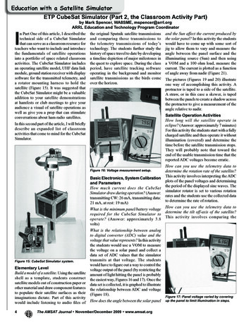
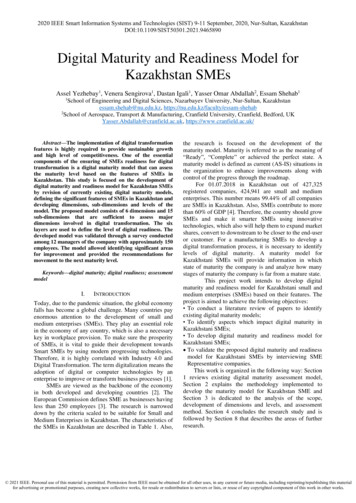
DJournal of Mechanics Engineering and Automation 11 (2021) 11-16doi: n of a Multi-axis Motion Control Platform Based onLabVIEW’s Fuzzy Control AlgorithmChuang Li and Yan ZhangLogistics Engineering College, Shanghai Maritime University, Shanghai 201306, ChinaAbstract: This paper presents a fuzzy control algorithm applied to the position control of a multi-axis motion platform to achievehigh precision motion control of the multi-axis motion platform. A LabVIEW-based multi-axis motion control system is designed.This system controls stepper motors using trapezoidal acceleration/deceleration pulse types and fuzzy control algorithms, whicheffectively avoids mechanical jitter and loss of step in the process of multi-angle motion of the stepper motor, and achieves accuratecontrol of the stepper motor. The TCP/IP (transmission control protocol/internet protocol) communication protocol is used, so thatdata are output stably and not lost in the process of transmission and communication, achieving the purpose of interconnection ofdifferent systems and remote control of equipment. This control system has been tested to maintain a high level of stability andrepeatability during actual operation.Key words: LabVIEW, stepper motors, multi-axis linkage, fuzzy algorithms, TCP/IP communication.1. IntroductionStepper motors are now widely used in a variety ofapplications because of their simple construction, easycontrol methods and the ability to achieve precisedisplacement positioning [1]. With the increasingrequirements of production automation, the demandfor stepper motor control has gradually increased andthe drive methods have become very sophisticated.This paper designs a multi-axis linkage motion controlplatform which consists of eight stepper motors. Thecombined motion of these eight stepper motorsenables vertical, horizontal, and angular motioncontrol of the platform. The platform’s specialmechanical structure is designed to carry a weight ofaround 50 kg and requires that the platform does notfall suddenly during movement or in the event of asudden power failure. This paper proposes the use offuzzy control algorithms for accurate displacementcontrol of stepper motors to eliminate errors due tofactors such as mechanical vibrations and theenvironment [2]. The stepper motor produces a returnerror during the reciprocating motion. The differencebetween the actual position of the stepper motor andthe target position is detected by a sensor, and thisreturn difference can be solved by using a fuzzycontrol algorithm [3]. In order to design a simple anduser-friendly human-machine interface, the systemuses LabVIEW software. LabVIEW is the commercialsoftware that is now used in all areas of modernscience and technology due to its simple programming,ease of understanding and mastery, as well as beingthe fastest growing and the most powerful integratedenvironment for graphical software development.2. Hardware Structure of a Multi-axisMotion Control System2.1 Structure of the Motion Control PlatformFig. 1 shows a schematic diagram of the outlinedimensions of the multi-axis motion control platform.This control system uses two multi-axis motioncontrol platforms, each with a platform that can moveCorresponding author: Chuang Li, master, research fields:power system optimization and intelligent control technology.horizontally fixed on each platform, and each platformis required to carry a load of 50 kg.
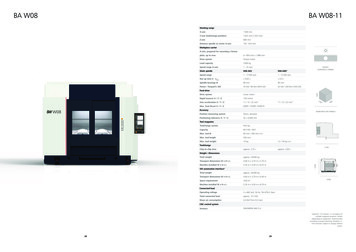
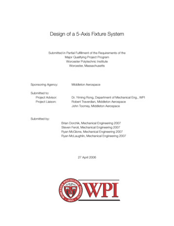
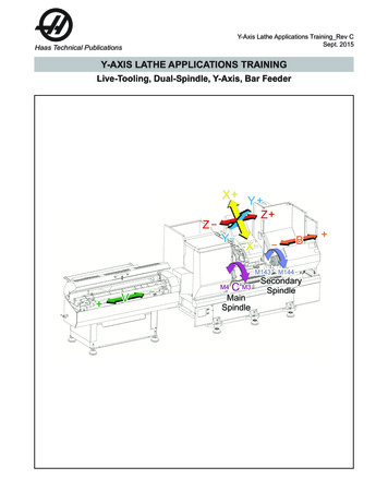
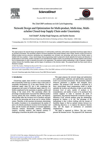
12Fig. 1Design of a Multi-axis Motion Control Platform Based on LabVIEW’s Fuzzy Control AlgorithmSchematic diagram of the multi-axis motion control platform.The multi-axis motion control platform has three axesand the stepper motor inside each axis is a two-phasestepper motor. The combined motion of the steppermotors in each axis enables vertical movement andangular adjustment of the platform. The platform isfixed with a sliding table that can be moved horizontally,so that the platform can also be moved horizontally.The control system requires the platform to be able tosupport a weight of about 50 kg. The mechanicalstructure of the traditional motion axis is generallydesigned with a stepper motor located on a screw, andthe horizontal, vertical, and angular adjustment of theplatform is achieved by controlling the movement ofthe stepper motor on the screw. This mechanicaldesign is extremely susceptible to sudden falls duringmovement and standstill when the load is 50 kg. Inorder to avoid sudden falls when the platform is inmotion, at standstill or even when the stepper motor ispowered off, a wedge structure has been added to theshaft of each stepper motor movement. As shown inFig. 2, the movement of the stepper motor drives themovement of the screw, causing the wedge to move inthe vertical direction, with a cardan shaft attached tothe top of the wedge, thus allowing displacementmovement of the individual axes of motion.This design effectively avoids the sudden fall of theplatform due to the heavy load when the platform is inmotion or at rest, and this mechanical structure canalso maintain the original motion posture when thestepper motor is powered off, effectively improvingthe stability of the three-dimensional motion platform.The physical multi-axis motion control system isshown in Fig. 3.2.2 Controllers and DrivesThe controller generates pulses and the steppermotor driver converts the electrical pulses into angulardisplacement signals so that the stepper motor movesat a fixed angle in the set direction. By controlling thenumber of pulses to control the angular displacementof the stepper motor, the frequency of the pulsescan also be controlled to control the speed andacceleration of the stepper motor, thus achieving thepurpose of speed regulation and precise displacement
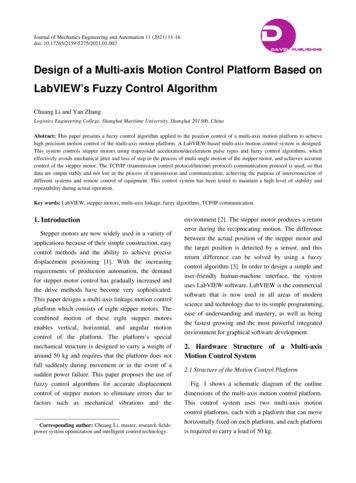
Design of a Multi-axis Motion Control Platform Based on LabVIEW’s Fuzzy Control AlgorithmFig. 213Schematic diagram of the wedge mechanism.Fig. 3 Physical view of the multi-axis motion controlplatform.control. The number of pulses sent by the controllercontrols the number of steps the stepper motor moves,the greater the number of pulses, the more steps thestepper motor moves; the frequency of pulses sent bythe controller controls the speed of the stepper motormovement, the greater the frequency of pulses, thefaster the stepper motor movement.The signal transmission of this control system usesTCP/IP (transmission control protocol/internet protocol)communication protocol to ensure the stability andaccuracy of the signal transmission. In this paper, thedriver and controller of the stepper motor are designedto be installed in a cabinet, which improves theintegration of the control system and providesconvenience for the operator, as shown in Fig. 4.Fig. 4Integrated controller and drive cabinet.The controller uses the PM16C-16 from TSUJI,Japan. This controller can output 16 pulses in a stablemanner, with a large range of output pulses, a highdegree of adjustability and the possibility of adjustingthe type of pulse. For different pulse frequencies cancontrol the controller output different types of pulse,and thus control the stepper motor more stableoperation, to a certain extent effectively avoid thestepper motor in the process of movement ofmechanical vibration phenomenon.The driver is a Melec model 750V1-01 from Japan,which is perfectly adapted to the controller and has adrive current range of 0.30-1.35 A up to 4,000subdivisions and a holding current of about 40% ofthe drive current. The circuit design of the drive usesconventional electronic components rather than
14Design of a Multi-axis Motion Control Platform Based on LabVIEW’s Fuzzy Control Algorithmintegrated circuits, increasing operational reliability.The internal design of the circuit contains limit switchsignal processing and hardware protection functions.3. Control Algorithms3.1 Movement Algorithms for Multi-axis MotionControl PlatformsDefine the coordinates of the center position of theplatform as (0, 0) and the coordinates of the U-axis,V-axis, and W-axis tilt cores as (0, 84), (-96, -55.4)and (96, -55.4) respectively. Since the screw diameterand screw pitch for each axis are 6 mm and 1 mm, it ispossible to calculate the amount of movement per unitpulse corresponding to the axis. It is assumed that thetarget breaking energy is [a] μm/pulse, the screw pitchis [b] mm and the drive breaking energy is set to [d]pulse/rev. The reduction ratio (wedge ratio) of themechanism is 1/4. Then in the linear direction we get:(1)Vertical:(2)From the above equation it is possible to calculatethe displacement of each axis of motion in real spacewhen the controller sends a certain number of pulses.The values of Z, 𝜃𝜃𝑥𝑥 and 𝜃𝜃𝑦𝑦 can be obtainedaccording to the mechanical structure of the controlplatform and for the definition of the coordinates ofeach axis of the control platform.(3)(4)(5)𝑆𝑆𝑡𝑡 (𝑈𝑈): Z-directional movement of the U-axis;𝑆𝑆𝑡𝑡 (𝑉𝑉): Z-directional movement of the V-axis;𝑆𝑆𝑡𝑡 (𝑊𝑊): Z-directional movement of the W-axis;𝑈𝑈𝑥𝑥 : 0 mm, 𝑈𝑈𝑦𝑦 : 84 mm;𝑉𝑉𝑥𝑥 : -96 mm, 𝑉𝑉𝑦𝑦 : -55.4 mm;𝑊𝑊𝑥𝑥 : 96 mm, 𝑊𝑊𝑦𝑦 : -55.4 mm.Therefore, according to the above movementcontrol algorithm to obtain the spatial position of themotion platform, each platform can achieve thedisplacement and spatial angle adjustment, and thenfrom the spatial position to convert the number ofpulses issued by the controller, to achieve themulti-axis motion control platform attitudeadjustment.3.2 LabView Algorithm and ImplementationThe motion control of this system is mainly themotion control of the stepper motor, and the motion ofthe stepper motor will generate errors, which is causedby the internal structure of the stepper motor and thecontrol means, therefore, reduce the error generatedby the stepper motor in the process of motion of thiscontrol system control algorithm research focus [4].Due to the special internal structure of the steppermotor, when the stepper motor is started, the pulsefrequency generated by the controller is too fast or thefrequency issued during deceleration is too slow,which may cause the stepper motor to oscillate or losesteps. The phenomenon occurs mainly during theacceleration and deceleration phases of stepper motors,where the loss of step or oscillation is related to thetype of pulse output from the controller [5]. Fig. 5shows the pulse type of a conventionally controlledstepper motor, which is a rectangular wave. When thecontroller outputs rectangular wave, due to the suddenrise and fall of the rising and falling edges of therectangular wave, it is very easy to make the steppermotor out of step phenomenon, when the controlleroutput signal frequency is too fast, the out-of-stepphenomenon will be more obvious. In order to avoidthis phenomenon in stepper motor, this paper uses atrapezoidal acceleration and deceleration pulse signal,as shown in Fig. 6. In contrast to rectangular waves,trapezoidal acceleration and deceleration pulse signalshave a slow rise and a slow fall on both the rising andfalling edges. The trapezoidal acceleration anddeceleration pulse signal allows the stepper motor tohave a slow increase in frequency during the start-upphase and to have a slow decrease during thedeceleration phase. Take the stepper motor movementfor a period of displacement, for example, in the
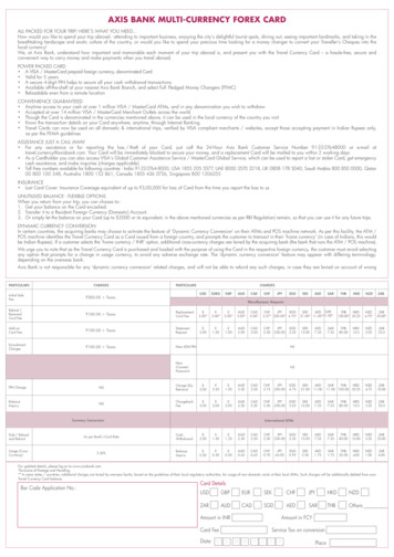
Design of a Multi-axis Motion Control Platform Based on LabVIEW’s Fuzzy Control Algorithm15speedMax SpeedCCWtimeStart commandFig. 5Stop commandFig. 7CWLogic diagram of the fuzzy control algorithm.Rectangular wave pulse signal.speedMax speedAcceleration curvetimeStart commandFig. 6C A Bstop commandTrapezoidal acceleration/deceleration pulse signal.stepper motor start-up phase, the motor first low-speedstart, followed by a certain acceleration graduallyspeeding up, and then uniform motion, when themovement is about to reach the specified position,take a certain acceleration deceleration movement,and finally to the target position to stop the movement.This prevents the stepper motor from not recognizingthe pulse signal and losing steps.The controller also generates errors in the processof sending out pulse signals. Factors such as thesensitivity of the controller’s internal electronics andthe environment can cause errors in the number ofpulses sent out by the controller. For example, whenthe controller receives a command to issue 10 pulses,it is possible that the controller will issue more than10 pulses or less than 10, and the stepper motor willtake one more step or one less step in the process ofmovement, which makes the stepper motor produce adisplacement error. In order to eliminate the effect ofthis error on the motion control system, for the designof this control system, a fuzzy control algorithm,commonly used in the control field, can be used.The logic of the fuzzy control algorithm in thispaper is similar to the infinite approximation approach,as shown in Fig. 7. Suppose that point A is the targetposition of the stepper motor movement, but thecontroller sends a few extra pulses to make themotor move to point B. At this point the sensor willdetect the actual position of the motor and calculatethe difference in distance between the actualposition and the target position. The program willconvert the number of pulses that the controller shouldoutput based on this displacement difference. Thecontroller receives the command to move towardspoint A again, but the actual position of the motormoves to point C. The above action will then berepeated until the motor moves to point A and themotor stops moving.The fuzzy control algorithm can well solve theproblem of controller internal chip and electroniccircuit causing the controller to mis-trigger pulses.The trapezoidal acceleration/deceleration pulsewaveform and fuzzy control algorithm can ensure thesmooth motion of the motion control platform toachieve the control accuracy and stability of thissystem.4. LabVIEW Control InterfaceFig. 8 shows the LabView control interface of thissystem. The control interface is simple and easy tooperate, and the operator can be familiar with thecontrol logic of the multi-axis motion control systemwithout much understanding, which improves theefficiency of work.
16Fig. 8Design of a Multi-axis Motion Control Platform Based on LabVIEW’s Fuzzy Control AlgorithmLabView control interface.5. ConclusionsReferencesThis paper introduces the design of a multi-axismotion control system platform based on LabViewlanguage. The hardware composition of this system ismainly introduced, and the trapezoidal accelerationand deceleration waveforms and fuzzy controlalgorithms are used to make the motion controlplatform move smoothly and reduce the motion errors.And the use of the TCP/IP communication protocolallows the system to be integrated with other controlsystems. The controller and driver can also be used formotion control of other stepper motors, reducing thecost of stepper motor control. In practical tests thesystem also maintains a high level of stability andaccuracy of movement, providing an importantreference for future multi-dwelling stepper motorcontrol.[1][2][3][4][5]Bindu, V., Unnikrishnan, A., and Gopikakumari, R. 2012.“Adaptive Fuzzy Logic Position Control of a StepperMotor with Extended Kalman Filter.” Presented at 2012International Conference on Power, Signals, Controls andComputation, Thrissur, India.Ahmadi, A., Tousizadeh Sadeghi, M., Mehdi Yzadani, A.,et al. 2012. “Designing an Optimal Fuzzy-PID Controllerfor Speed Tracking of Stepper Motor.” Presented at 2012IEEE Symposium on Industrial Electronics andApplications, Bandung, Indonesia.Woo, Z., Chung, H., and Lin, J. 2000. “A PID TypeFuzzy Controller with Self-tuning Scaling Factors.”Fuzzy Sets and Systems 115: 321-6.Kamalasadan, S. 2007. “A New Intelligent Control forthe Precision Tracking of Permanent Magnet StepperMotor.” Presented at 2007 IEEE Power EngineeringSociety General Meeting.Mohammad Zadeh, A., Atashpaz Gortari, E., and Lucas,C. 2008. “Vehicle Fuzzy Controller Design UsingImperialist Competitive Algorithm.” Presented at 2008IEEE World Congress on Computational Intelligence.
The controller generates pulses and the stepper motor driver converts the electrical pulses into angular displacement signals so that the stepper motor moves at a fixed angle in the set direction. By controlling the number of pulses to control the angular displacement of the stepper motor, the frequency of the pulses