Transcription
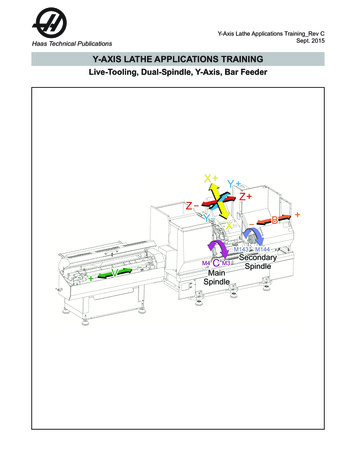
Haas Technical PublicationsY-Axis Lathe Applications Training Rev CSept. 2015Y-AXIS LATHE APPLICATIONS TRAININGLive-Tooling, Dual-Spindle, Y-Axis, Bar Feeder
Haas Technical PublicationsY-AXIS LATHE APPLICATIONS TRAININGY-Axis Lathe Applications Training Manual Rev CSept 2015Page 2 of 100
Haas Technical PublicationsY-AXIS LATHE APPLICATIONS TRAININGContentsINTRODUCTION . 5SECTION 1.HOMING THE MACHINE . 7POWER-UP RESTART . 7G28, G53. 9SECTION 2.MACHINE AXES, PLANES DEFINED . 11AXES (XYZABCV), TRAVEL LIMITS . 12SECTION 3.SPINDLE DIRECTION, SPEED. 15PLANES G17, G18, G19. 17SECTION 4.RESOURCES . 19ES DOCUMENTS . 19MACHINE LAYOUT DRAWINGS . 233rd PARTY AFTERMARKET RESOURCES . 24SECTION 5.LIVE-TOOL CANNED CYCLES . 27CHANGES BETWEEN VERSIONS . 27AXIAL CANNED CYCLES. 28RADIAL CANNED CYCLES . 30SECTION 6.TOOL OFFSETS . 35SECTION 7.AUTOMATIC TOOL PROBE (ATP) . 37SECTION 8.DUAL SPINDLE LATHES. 38COMMON DUAL SPINDLE (DS) M/G CODES. 38M154 C-AXIS ENGAGE . 38M14 / M114 SPINDLE BRAKE . 39G04 DWELL . 40G14, MACHINING ON SECONDARY SPINDLE . 40G199 SPINDLE SYNCHRONIZATION . 41R PHASE, SPINDLE SYNC (G199) . 42SPINDLE OVERRIDES AND LOAD MONITORING . 45M19 VS M154 SPINDLE ORIENTATION . 46SECTION 9.BAR FEEDER . 47INTRODUCTION. 47COMMON BAR FEEDER CODES. 48BAR FEEDER APPLICATIONS QUICK-START GUIDE . 50BAR PULLING WITH A DS MACHINE. 51G160/G161 BAR FEEDER COMMANDS . 51Y-Axis Lathe Applications Training Manual Rev CSept 2015Page 3 of 100
Haas Technical PublicationsY-AXIS LATHE APPLICATIONS TRAININGSECTION 10.LIVE-TOOL MILLING, G17/G19 . 53G17 (XY) PLANE AXIAL MILLING . 53DIRECT XY AXIAL MILLING, G17 (XY) PLANE . 53G112 XY TO XC INTERPRETATION . 57DIRECT XC AXIAL MILLING, G17 (XY) PLANE . 59ALIGNMENT OF AXIAL CANNED CYCLES, G17 MILLING. 60G19 (YZ) RADIAL LIVE-TOOLING MILLING . 61SECTION 11.M38 / M39 SSV SPINDLE SPEED VARIATION . 63SECTION 12.SETTING XY CENTERLINE . 65INSTRUCTIONS FOR SETTING TURRET POCKET X ANDY AXIS CENTERLINES, VDI/BOT/HYBRID . 65FREQUENTLY ASKED QUESTIONS . 69FUTURE ENHANCEMENTS . 70APPENDIX A.AXIAL LIVE-TOOL CANNED CYCLES . 71APPENDIX B.RADIAL LIVE-TOOL CANNED CYCLES. 77APPENDIX C.G17 LIVE-TOOL MILLING EXAMPLE . 83APPENDIX D.LATHE TOOL PRESETTER CALIBRATION. 87APPENDIX E.PRINTABLE REFERENCE MATERIAL . 89Y-Axis Lathe Applications Training Manual Rev CSept 2015Page 4 of 100
Haas Technical PublicationsY-AXIS LATHE APPLICATIONS TRAININGINTRODUCTIONThis training document is intended to be used by Certiied Haas Application’s Engineers.This document lays the framework for a 2-day Live-Tool Lathe Applications class. Chapters1-8 to be covered on day one, and chapters 9-12 to be covered on the second day.The information given builds on what you have already learned from the Haas Lathe andMill Manuals. The reader must already have a basic knowledge of Haas G and M Codeprogramming for both mills and lathes to get the most out of this document.This document’s purpose is to give the reader a working knowledge of the unique codesand practices needed to operate a Haas Lathe with the Live-Tooling, Dual-Spindle, Y-Axisor Bar Feeder options.Software Version L11.10A was used. Upcoming software changes may render some ofthese notes obsolete.The latest lathe manuals are full of new and useful information on Y-Axis lathes. Be sure tolook at these, and have your customers download the latest versions.New Machine Layout Drawings are also available on the Haas Website.Y-Axis Lathe Applications Training Manual Rev CSept 2015Page 5 of 100
Haas Technical PublicationsY-AXIS LATHE APPLICATIONS TRAININGY-Axis Lathe Applications Training Manual Rev CSept 2015Page 6 of 100
Haas Technical PublicationsY-AXIS LATHE APPLICATIONS TRAININGSECTION 1.HOMING THE MACHINEPOWER-UP RESTARTAll of our ST lathes can be Zero Returned after Power On with asingle button press, POWER UP RESTART.Our Dual-Spindle and Toolroom Lathes (DS, TL models) require the operator to home eachaxis individually. This was added as a safety feature, to lessen the chance of a collision.If POWER UP RESTART is pressed, on a DS or TL lathe, “FUNCTION LOCKED” will bedisplayed.Check for Turret / Part interference, and make sure that one or both of the chucks isunclamped (DS only), and then ZERO RET SINGL each axis, in the following order:DS Machines: B Y X Z A C VThe B-Axis is the Tailstock.The A-Axis is the Turret. Homing the A-Axis will bring tool T1 into cutting position.The V-Axis is the optional bar feeder.Note that (5) Axes can be viewed from the Position Screen at any one time.Y-Axis Lathe Applications Training Manual Rev CSept 2015Page 7 of 100
Haas Technical PublicationsY-AXIS LATHE APPLICATIONS TRAININGTo change which (5) Axes are displayed, we will:Press the POSIT keyPress the F2 keySelect up to 5 axes you would like to display, by highlighting them and then pressing theWRITE ENTER keyPress F2 when inishedNote that the V-Axis is now visible on this DS machineY-Axis Lathe Applications Training Manual Rev CSept 2015Page 8 of 100
Haas Technical PublicationsY-AXIS LATHE APPLICATIONS TRAININGG28, G53HOMING THE MACHINEYou must always home the Y-Axis before the X. This must be done whether you arePowering-Up the machine, or if you command the X axis to the home position in a program.The next section, Machine Axes, gives more detail on this. See the following example.G53 Y0.0G53 X0.0Note that the lathe will automatically return the Y-Axis to the home position after any toolchange.On a Mill, G90 is an Absolute move, and G91 is an Incremental move (see mill manual).On a Lathe, XYZ are used for Absolute moves and UVW are used for Incremental moves.You can send the Y-Axis to the home position by entering G53 Y0.0. A G28 followed by aU or W will home the X or Z-Axis, but the use of a G28 V0. is not currently permitted. Tokeep things simple for the customer, showing them how to use a G53 for all axis-homemovements is advised.Because the V-Axis is used as both our bar feeder Axis and for incremental Y-Axismovement, a special code is needed to let the control know which axis we intended tomove. A G160 command, prior to a V move, lets the control know that the move is for thebar feeder, and not an incremental move of the Y-Axis. When the move is complete, a G161must be called.To move the bar feeder V-Axis 1" to the right of its Home Position (Absolute Move), wewould command:G160G00 V-1.0G161Note that a G00 V-1.0 command, without the G160, would move the Y-Axis incrementally-1.0.To move the bar feeder V-Axis 1" to the right of its present position (Incremental Move), wewould command:G105 J1.0The Current Bar Length, variable 3110, is updated when the above G105 J1.0 commandis called. Commanding the bar feeder V-Axis directly (G00 V1.0), outside of the G105command, will not update the Current Bar Length (variable 3110).Y-Axis Lathe Applications Training Manual Rev CSept 2015Page 9 of 100
Haas Technical PublicationsY-AXIS LATHE APPLICATIONS TRAININGY-Axis Lathe Applications Training Manual Rev CSept 2015Page 10 of 100
Haas Technical PublicationsY-AXIS LATHE APPLICATIONS TRAININGSECTION 2.MACHINE AXES, PLANES DEFINEDNot all of the axes shown are available on every machine.Y-Axis Lathe Applications Training Manual Rev CSept 2015Page 11 of 100
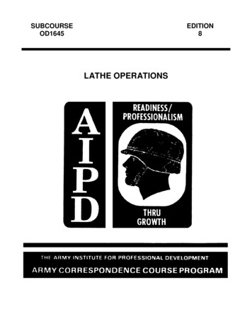
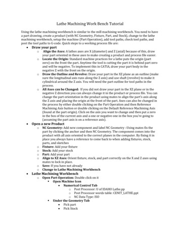
Haas Technical PublicationsY-AXIS LATHE APPLICATIONS TRAININGAXES (XYZABCV), TRAVEL LIMITSX-AxisAll X positions are programmed as diameters. This applies to milling, as well as turning.The top of a 1.0" diameter bar in the chuck would be X1.0, the bottom of that bar would beX-1.0.Incremental X-Axis moves are commanded with a U move. These are also in diameter.If you command “G00 U-1.0” in MDI, the turret will move incrementally towards the spindleby .5" which is -1.0" diameter.The only X moves that are not deined as diameters are arc center-points and radius.These are our “I” and “R” values in G02/G03 moves. We would use the actual size of theradius, not multiplying the “I” by 2, as if it were a diameter. See the Live-Tool Milling sectionfor more information and examples.X-Axis Travel LimitsEach machine has different X-Axis travellimits. This is important when decidingwhat approach to take when live-toolmilling. If you are axial-milling with a .5"diameter endmill, you will need to travelto X-1.5 in order to mill a 1" boss. Thismay work well on an ST-20SS, but astandard ST-20 would not have the travelto reach that far below the X centerline. Inthat instance we would program the bossusing XC moves, or a G112 cycle.Values shown are actual inches belowX centerline, not diameter valuesDS-30SSY ShownY-Axis Lathe Applications Training Manual Rev CSept 2015Page 12 of 100
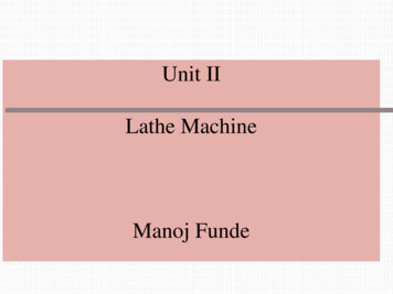
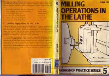
Haas Technical PublicationsY-AXIS LATHE APPLICATIONS TRAININGY-AxisThe Y-Axis on lathes moves in the oppositedirection of what you may be used to on yourmills. The positive direction is towards theoperator, the negative is away. Y-Axis moves areprogrammed radially, unlike the X-Axis which isprogrammed with diameter values.Incremental Y-axis moves are commanded with a V.If you command “G00 V-1.0” in MDI, the turret will move incrementally away from theoperator by 1.0"When milling in the G19 (YZ) plane, or turning in the G18 (XZ) plane, you can program anarc with a “J” or an “R”. See the Live-Tool Milling section for more information.Y-Axis Travel LimitsEach Haas Y-Axis lathe has /- 2.00” oftravel.There is a narrow corner of the workenvelope, where a positive Y-Axis movementis constrained, as the X-Axis reaches itsphysical limit. This area is marked as “B”in the diagram to the right. This is why werequire the Y-Axis to be homed irst, beforethe X-Axis.The following command would not beexecuted, because the coordinates falloutside of the machine’s travel limits:G53 G00 Y2.0G53 G00 X0.0Y-Axis Lathe Applications Training Manual Rev CSept 2015Page 13 of 100
Haas Technical PublicationsY-AXIS LATHE APPLICATIONS TRAININGZ-AxisThe Z-Axis moves the turret away from the Main Spindle (Z ), or towards it (Z-).Incremental Z-Axis moves are commanded with a W.If you command “G00 W-1.0” in MDI, the turret will move incrementally towards the MainSpindle by 1.0”.Y-Axis Lathe Applications Training Manual Rev CSept 2015Page 14 of 100
Haas Technical PublicationsY-AXIS LATHE APPLICATIONS TRAININGSECTION 3.SPINDLE DIRECTION, SPEEDThe following will command the live-tool to spin in the forward direction, at 2000 rpm:G97 M133 P2000We need to be very careful when using right-angled or extended live-tooling holders. Theseoften contain gearing that will turn the tool in the opposite direction of the drive. Test all livetool holders to make sure the tool is turning in the intended direction before cutting a part.You can command the Secondary Spindle in the same manner:G97 M143 P2000While we may have a need to rotate the Secondary Spindle in this way, all machining onthe second spindle must use a G14 Secondary Spindle Swap command. See the DualSpindle section for more information. A brief example is shown below:G14 (Spindle Swap On)G97 M03 S2000G15 (Spindle Swap Off)All tapping speeds are commanded with an S value on the Haas Lathe, regardless ofwhether we are using the Main Spindle, the Secondary Spindle, or Live-Tooling.Y-Axis Lathe Applications Training Manual Rev CSept 2015Page 15 of 100
Haas Technical PublicationsY-AXIS LATHE APPLICATIONS TRAININGWhen commanding a spindle to rotate in the forward direction(M03, M143, M133), itwill appear to move counter-clockwise (CCW), from the operator’s perspective.Below is a visual aid showing the direction of the Main and Secondary Spindles on a DSmachine, for turning (M3/M143), C-Axis rotation (M154), and Spindle Orientation (M19/M119).From the illustration, we see that the following command will move the main spindleclockwise (from the perspective of the part face) by 90 G54M154G00 C90. (ROTATES THE SPINDLE CLOCKWISE, IN OPERATOR VIEW)Y-Axis Lathe Applications Training Manual Rev CSept 2015Page 16 of 100
Haas Technical PublicationsY-AXIS LATHE APPLICATIONS TRAININGPLANES G17, G18, G19We use planes (G17, G18, G19) on our Y-Axis lathes to tell the control which axes (XYZ)G02 and G03 circular motions are performed in, and which direction to move when using acanned cycle (depths, rapid planes).Calling up the wrong plane can cause our arcs to become distorted and our canned cyclesto drill in the wrong directions.If we are programming straight lines, from one XYZ point to another, the plane selection willnot have an effect on our part.Note that there was a look-ahead issue in early L11.xx series software (prior to L11.06),where the control could change planes too soon, when another plane was called out later inyour program.The solution is to either:1)Stop look-ahead before your plane change by placing an M01, /, M00, or G103 P1;;;before any plane change (G17, G18, G19) or2)Upgrade your software to the latest L11.10A software or newer.Y-Axis Lathe Applications Training Manual Rev CSept 2015Page 17 of 100
Haas Technical PublicationsY-AXIS LATHE APPLICATIONS TRAININGG17, XY PlaneG17 is used when creating arcs (G02, G03) in the XYplane, for live-tool axial milling.Live-tool canned cycles are designed to run either axially(i.e. G83) or radially (G243). For this reason, all live-toolcanned cycle can be run in the default G18 plane. Do notrun your axial live-tool canned cycles in the G17 plane.It must be noted that the live-tooling canned cycle examples in Lathe Manual 96-8700 RevAL show the use of the G17 plane for axial live-tool drilling cycles. This was incorrect. Haveyour customers download the latest lathe manual (Rev AN or newer) from the website.See the sections for Live-Tool Canned Cycles and Live-Tool Milling for examples, and theuse of planes.G18, XZ PlaneG18 is used for creating arcs (G02, G03) in the XZ plane in our turning operations, and isthe default plane for all of our Live-Tool Canned Cycles.Live-tool canned cycles do not abide by the G17, G18, and G19 plane rules. Teach yourcustomers to use the G18 plane for all live-tool canned cycles (L11.02 and newer). Thiswas done as a means to simplify all canned cycles and prevent collisions on our customer’smachines.See the sections for Live-Tool Canned Cycles and Live-Tool Milling for examples, and theuse of planes.G19, YZ PlaneG19 is used for creating arcs (G02, G03) in the YZplane, for live-tool radial milling.See the sections for Live-Tool Canned Cyclesand Live-Tool Milling for examples, and the use ofplanes.Y-Axis Lathe Applications Training Manual Rev CSept 2015Page 18 of 100
Haas Technical PublicationsY-AXIS LATHE APPLICATIONS TRAININGSECTION 4.RESOURCESES DOCUMENTSListed below are important ES Documents that you need to be familiar with. ES0335 Lathe Tooling and Toolholding Information ES0603 Spindle Liners ES1003 Spindle, Chuck and Drawtube Specs ES0088 Spindle Torque Charts ES1001 Parts Catcher Option ES0761 Chuck WeightsThe latest versions of these documents can be found on the Portal at :PORTAL Sales ES DocsY-Axis Lathe Applications Training Manual Rev CSept 2015Page 19 of 100
Haas Technical PublicationsY-AXIS LATHE APPLICATIONS TRAININGES0335 Lathe Tooling and Toolholding Information.This document gives us part numbers for lathe tooling, and helps deine the differencesbetween lathe turret designs.Y-Axis Lathe Applications Training Manual Rev CSept 2015Page 20 of 100
Haas Technical PublicationsY-AXIS LATHE APPLICATIONS TRAININGES0603 Lathe Spindle LinersThis document shows everything you needto choose and install spindle liners on yourcustomer’s speciic machine.Y-Axis Lathe Applications Training Manual Rev CSept 2015Page 21 of 100
Haas Technical PublicationsY-AXIS LATHE APPLICATIONS TRAININGES0088 Spindle Torque ChartsThis document shows the Torque Curves for the customer’s machine spindles, and theirlive tooling. This will help you decide the optimal RPM to run a spindle for a certain task.Y-Axis Lathe Applications Training Manual Rev CSept 2015Page 22 of 100
Haas Technical PublicationsY-AXIS LATHE APPLICATIONS TRAININGMACHINE LAYOUT DRAWINGSEvery customer with a Haas Y-Axis lathe should have, and be familiar with, theMachine Layout Drawing (MLD) for his machine.These drawings give travel limits and other information, speciic to each machine.These drawings can be downloaded from the Haas website, by following the link shown foreach machine.Y-Axis Lathe Applications Training Manual Rev CSept 2015Page 23 of 100
Haas Technical PublicationsY-AXIS LATHE APPLICATIONS TRAINING3rd PARTY AFTERMARKET RESOURCESLive-Tool Drive Units Exsys/Eppinger – http://www.exsys-tool.com Parlec – http://www.parlec.com Heimatec – http://www.heimatecinc.com Benz – http://www.benz-inc.com MD Tooling - http://mdtooling.com MTS Driven Tools - http://www.mtsdriventools.co.uk WTO - http://www.wto-usa.com Von Ruden - http://www.vonruden.com Velocity - http://www.velocityproducts.com Holdwell - http://www.holdwell.com Global CNC - http://www.globalcnc.comSteady Rests Kitagawa – http://www.kitagawa.com LMC Workholding – http://www.lmcworkholding.com LNS America – http://www.lns-america.com Rest In Peace – http://steadyrest.net Rohm Products – http://www.us.roehm.biz ATS Workholding – http://www.ats-s.com SMW Autoblok – http://www.smwautoblok.comY-Axis Lathe Applications Training Manual Rev CSept 2015Page 24 of 100
Haas Technical PublicationsY-AXIS LATHE APPLICATIONS TRAINING213There are several tooling options worth mentioning for those with DS machines.1)Look at ES document ES0335, for the Extended Twin Bore and Extended Twin Turnbolt-on toolholders for the VB24 turret.2)Extended reach axial double ER32 live-tooling is available from companies like BENZ(www.benz-inc.com).3)Companies like Heimatec also make narrow stick tool holders that nest in between livetooling heads. This increases the number of tools a turret can accommodate.Y-Axis Lathe Applications Training Manual Rev CSept 2015Page 25 of 100
Haas Technical PublicationsY-AXIS LATHE APPLICATIONS TRAININGY-Axis Lathe Applications Training Manual Rev CSept 2015Page 26 of 100
Haas Technical PublicationsY-AXIS LATHE APPLICATIONS TRAININGSECTION 5.LIVE-TOOL CANNED CYCLESCHANGES BETWEEN VERSIONSRunning L11.02 or newer?Use the G18 plane for all of your Axial and Radial live-tooldrilling/tapping/boring canned cycles.Use only designated Radial Canned Cycles (i.e., G241) fordrilling/tapping/boring radially.The Haas lathe uses different G codes for Axial and Radial Canned Cycles.To Peck Drill axially (in the Z direction), we will use a G83. To Peck Drill radially (along theX-Axis), we will use a G243. Both the G83 (axial) and G243 (radial) Peck Drill CannedCycles are called using the G18 plane.Prior to L11.06 it was possible to force a G83 (or similar) canned cycle to cut radiallyinstead of axially by changing the plane from a G18 to a G17. Since L11.06 the control willignore all plane call-ups, and will run Axial Cycles along the Z-Axis only and Radial Cyclesalong the X-Axis only.Designated Radial Canned Cycles (G241-249, G195-196) were made usable in L11.02.These cycles will always cut along the X-Axis, regardless of plane selection.Live-Tooling Lathes with software older than L11.02 must use the default G18 plane to drillaxially, and the G17 plane to drill Radially (O.D.).Note that the examples shown in Lathe Manual 96-8700, Rev. AL, are incorrect when theyshow axial cycles using a G17.Many changes have been made to our Lathe Manual recently. Be sure to have yourcustomers download the latest revision (Rev. AN or newer).Axial Cycles: G81, G82, G83, G85, G86, G87, G88, G89, G95, and G186Radial Canned Cycles: G195, G196, G241, G242, G243, G245, and G249Y-Axis Lathe Applications Training Manual Rev CSept 2015Page 27 of 100
Haas Technical PublicationsY-AXIS LATHE APPLICATIONS TRAININGAXIAL CANNED CYCLESBelow are our Axial Canned Cycles, as listed in the manual (96-8700 Rev AN April):Axial Cycles:G81 Drill Canned Cycle (Group 09)G82 Spot Drill Canned Cycle (Group 09)G83 Normal Peck Drilling Canned Cycle (Group 09)G85 Boring Canned Cycle (Group 09)G86 Bore and Stop Canned Cycle (Group 09)G87 Bore and Manual Retract Canned Cycle (Group 09)G88 Bore and Dwell and Manual Retract Canned Cycle (Group 09)G89 Bore and Dwell Canned Cycle (Group 09)G95 Live Tooling Rigid Tap (Face) (Group 09)G186 Reverse Live Tool Rig Tap (For Left Hand Threads) (Group 09)Refer to Lathe Manual 96-8700, Revision AN or newer, for detailed descriptions of thesecycles. That manual has been updated, and contains the latest information on these cycles.Y-Axis Lathe Applications Training Manual Rev CSept 2015Page 28 of 100
Haas Technical PublicationsY-AXIS LATHE APPLICATIONS TRAININGIn order to use Live Tool Canned Cycles, Parameter 315, Bit 1, NO SPIND CAN needs tobe set to “1”. There is more information on this, in the FAQ section of this document.It is always best to use the M154 (C-Axis) to orientate the Main Spindle, as opposed tousing an M19. This is a much more accurate and repeatable method. The SecondarySpindle on a DS machine has no C-Axis, and indexing on that spindle must be commandedwith an M119, or a G14 M19. See the Dual Spindle section for more information.The following axial drilling example will work on all software versions:Axial Cycle Example:%O00810 (G81- AXIAL DRILLING)T2323G54 G18 G98(USE G18 PLANE)M154 (Engage C-Axis)G00 X6. C0. Z1.G00 X2. Z0.25G97 P1500 M133G81 G98 X1. Z-1. F10.C135. (DRILL SECOND HOLE AT C135.)G00 G80 Z0.25M155M135M09G28 H0. (Unwind C-Axis)G00 X6. Z1.M30%Program examples for each of the Axial Canned Cycles, can be found at the end ofthis document, in Appendix A.Y-Axis Lathe Applications Training Manual Rev CSept 2015Page 29 of 100
Haas Technical PublicationsY-AXIS LATHE APPLICATIONS TRAININGRADIAL CANNED CYCLESRadial Canned Cycles:G195 Forward Live Tool Radial Tapping (Diameter) (Group 00)G196 Reverse Live Tool Radial Tapping (Diameter) (Group 00)G241 Radial Drill Canned Cycle (Group 09)G242 Radial Spot Drill Canned Cycle (Group 09)G243 Radial Normal Peck Drilling Canned Cycle (Group 09)G245 Radial Boring Canned Cycle (Group 09)G249 Radial Bore and Dwell Canned Cycle (Group 09)Refer to Lathe Manual 96-8700, Revision AN or newer, for detailed descriptions of thesecycles. That manual has been updated, and contains the latest information on these cycles.It is always best to use the M154 (C-Axis) to orientate the Main Spindle, as opposed tousing an M19. This is a much more accurate and repeatable method. The SecondarySpindle on a DS machine has no C-Axis, and indexing on that spindle must be commandedwith an M119, or a G14 M19. See the Dual Spindle section for more information.The G195 radial tapping cycle is unique, and differs from other canned cycles. See thecurrent manual (96-8700 Rev AN April or newer) for a full description.The tool must be positioned to the Start Point before commanding G195/G196. This G codeis called for each hole being tapped. The cycle begins from the current position, tapping tothe X-Axis depth speciied. An “R” plane is not used. Only X and F values should be usedon G195/G196 lines. The tool must be positioned to the Start Point of any additional holesbefore commanding G195/G196 again.Y-Axis Lathe Applications Training Manual Rev CSept 2015Page 30 of 100
Haas Technical PublicationsY-AXIS LATHE APPLICATIONS TRAININGProgram Example%O01950 (LIVE TAP - RADIAL)T101M154G00 G54 X6. C0. Y0. Z1.G00 X3.25 Z-0.75 C0. Y0.G99S500G195 X2. F0.05G00 C180.G195 X2. F0.05G00 C270. Y-1. Z-1.G195 X2. F0.05G00 G80 Z0.25M135M155G00 G28 H0.G00 X6. Y0. Z3.G98M30%(Engage C-Axis)(Start Point)(Must Set to Feed Per Rev. for this cycle)(Taps to X2., bottom of hole)(Index C-axis. New Start Point)(Optional Y and Z-axis positioning, New Start Point)(Returns C-Axis to Home Position)While not shown above, the G195 cycle can be used to Vector Tap along the X and Z axes.Vector tapping using the Y-Axis is not allowed.Program examples for each of the Radial Canned Cycles, can be found at the end ofthis document, in Appendix B.Y-Axis Lathe Applications Training Manual Rev CSept 2015Page 31 of 100
Haas Technical PublicationsY-AXIS LATHE APPLICATIONS TRAININGThe following is a typical G243 Radial Normal Peck Drilling Canned Cycle:(G243 - RADIAL PECK DRILLING USING Q)G54(Work offset G54)G00 G53 Y0(Home Y-axis)G00 G53 X0G00 G53 Z0T303M154(Engage C Axis)M133 P2500 (2500 RPM)G98(IPM)G00 X5. Z-0.75 Y0G243 X2.1 Y0.125 Z-1.3 C35. R4. Q0.25 F20.(Drill to X 2.1)X1.85 Y-0.255 Z-0.865 C-75. Q0.25G00 G80 Z1.M135(Stop live tool spindle)G00 G53 Y0G00 G53 X0G00 G53 Z0M00Y-Axis Lathe Applications Training Manual Rev CSept 2015Page 32 of 100
Haas Technical PublicationsY-AXIS LATHE APPLICATIONS TRAININGFor L11.01 machines and older, you can use standard axial canned cycles to drill radially,by changing the plane from G18 to G17, and changing your depths from a Z to an Xdiameter value.The following radial drilling example is only to be used if you have version L11.01 or older.%O00831 (G83 - RADIAL PECK TEST)(THIS PROGRAM DRILLS RADIALLY)(IT IS ONLY VALID ON SOFTWARE)(VERSIONS L11.01 AND OLDER)(FOR L11.02 AND NEWER, USE G243)G54G53 G00 Y0.G53 G00 X0.G53 G00 Z-7.T505 (DRILL)G18G98M154(Engage C-Axis)G00 G54 X6. C0. Z1.G00 X6. Z0.25G97 P1500 M133(M08)(SWITCH TO G17 FOR RADIAL ON OLDER LATHE)(THE DEPTH IS AN X VALUE, FOR RADIAL)G17 G83 G98 X1. I1. J0.5 K0.5 R5. F10.C135.C225.G00 G80 Z0.25M155M135M09G18 (RETURN TO G18)G28 H0. (Unwind C-Axis)G00 G53 Y0.G00 G53 X0.M30%Y-Axis Lathe Applications Training Manual Rev CSept 2015Page 33 of 100
Haas Technical PublicationsY-AXIS LATHE APPLICATIONS TRAININGY-Axis Lathe Applications Training Manual Rev CSept 2015Page 34 of 100
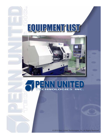
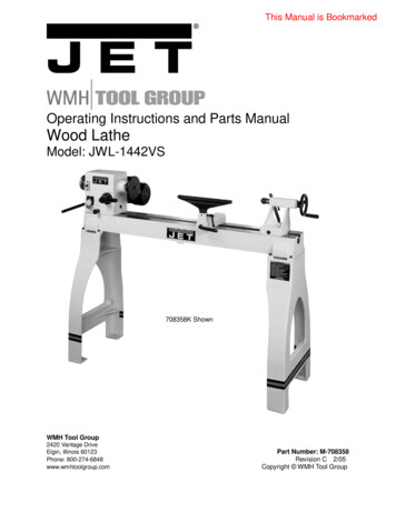
Haas Technical PublicationsY-AXIS LATHE APPLICATIONS TRAININGSECTION 6.TOOL OFFSETSSETTING Work Offsets WITH MISMATCHED TOOL T/H (T131/T101)Dual Spindle DS machines will often have two or more tools sharing the same turretposition.T101T131Do not use tools with mismatched Tool and Offset numbers(T131 vs. T101) to set a Work Offset (i.e., G54).The O.D. turning tool facing the Main Spindle, in the picture above, is T101. This is Tool 1,using Offset 1.The O.D. turning tool facing the Secondary Spindle is T131. This is Tool 1, using Offset 31.Any offset other than 1 could have been used.The Haas lathe has 50 available Tool Offsets.Currently (L11.10A) we are able to touch off tools whose T number matches its Offsetnumber. In the case above, we could use the optional Automatic Tool Probe (ATP) for T101,but would touch off T131 manually (paper on part), for the Secondary Spindle operation.When setting a Work Offset, the control uses the Tool Offset that corresponds with thecurrent turret position. In our example, this is Tool Offset 1. If a tool is using an offset thatdoes not match its turret position (like T131), it must not be used to set a Work Offset (ZFACE MEAS).Y-Axis Lathe Applications Training Manual Rev CSept 2015Page 35 of 100
Haas Technical PublicationsY-AXIS LATHE APPLICATIONS TRAININGThe Applications Department is currently reviewing test software that enhances thefunctionality of the Automatic
Y-Axis Lathe Applications Training Manual_Rev C Sept 2015 Page 12 of 100 Haas Technical Publications Y-AXIS LATHE APPLICATIONS TRAINING DS-30SSY Shown Values shown are actual inches below X centerline, not diameter values AXES (XYZABCV), TRAVEL LIMITS X-Axis All X positions are programmed as diameters.