Transcription
Design of a 5-Axis Fixture SystemSubmitted in Partial Fulfillment of the Requirements of theMajor Qualifying Project ProgramWorcester Polytechnic InstituteWorcester, MassachusettsSponsoring Agency:Submitted to:Project Advisor:Project Liaison:Middleton AerospaceDr. Yiming Rong, Department of Mechanical Eng., WPIRobert Traverdian, Middleton AerospaceJohn Toomey, Middleton AerospaceSubmitted by:Brian Dorchik, Mechanical Engineering 2007Steven Feroli, Mechanical Engineering 2007Ryan McGlone, Mechanical Engineering 2007Ryan McLaughlin, Mechanical Engineering 200727 April 2006
Design of a 5-Axis Holding FixtureAug 06 - May 07AbstractThe Middleton Aerospace Corporation designs and manufactures specialty aerospaceparts for aircraft manufacturers. Many of the parts require sophisticated fixturing in orderto be machined. Middleton operates a variety of CNC machine brands all of which havedifferently designed tables. They needed a way of sharing the fixturing systems with all ofthe machines. After reviewing the fixtures and machines, we designed, manufactured, andtested a fixturing system which would eliminate the need for different fixtures for eachmachine.Worcester Polytechnic Institutei
Design of a 5-Axis Holding FixtureAug 06 - May 07Table of ContentsAbstractTable of ContentsList of TablesList of FiguresExecutive Summary1.0 Introduction2.0 Background and Literature Review2.1 5-Axis CNC Machining2.2 Fixture Design2.2.1 The “5 steps of fixture design”2.2.2 Work Holding2.2.3 Locating2.3 Part Holding Methods2.3.1 Bolting2.3.2 Clamping2.3.3 Ball Locks3.0 Methods3.1 Part Analysis3.2 Current Fixture Analysis3.3 Sub Plate Design3.4 Design Analysis4.0 Results and Analysis4.1 Sub Plate Design4.1.1 Dimensions4.1.2 Material4.2 Fixture Modifications4.3 Cost Analysis5.0 ConclusionReferencesAppendicesAppendix A: Sponsor DescriptionAppendix B: Project TimelineAppendix C: Part AnalysisC.1 Part 6066T50G02C.2 Part 6057T42G02C.3 Part 70351-38111-105C.4 Part ComparisonAppendix D: Additional FilesWorcester Polytechnic 1242424252728292930313738383832ii
Design of a 5-Axis Holding FixtureAug 06 - May 07List of TablesTable 2.1: Run Costs9List of FiguresFigure 2.1: The Axis Orientations on the Cincinnati T353Figure 2.2: T35 Pallet4Figure 2.3: Degrees of Freedom & 3-2-1 Rule14Figure 2.4: Machine Vice15Figure 2.5: Ball Lock Locating Shank16Figure 2.6: Ball Lock Linear Bushing16Figure 2.7: Ball Lock Receiving Bushing16Figure 3.1: Examining Current Processes Flow Diagram17Figure 4.1: Fixturing System Flow Chart21Figure 4.2: Proposed Sub-plate Design and Hole Pattern22Figure 4.3: Sub-plate to Table Attachment23Figure 4.4: Ball Lock System23Figure 4.5: Fixturing System Mock-Up Exploded and Assembled View25Figure 4.6: Break Even Cost Analysis of Sub-plate Design26Figure B.1: Estimated Project Timeline30Worcester Polytechnic Instituteiii
Design of a 5-Axis Holding FixtureAug 06 - May 07Executive SummaryThe Middleton Aerospace Corporation designs and manufactures specialty aerospaceparts for aircraft manufacturers. They currently used two different types of 5-axis CNCmilling machines, which have different work table configurations. Middleton approachedWPI with the task of creating a universal fixture system for their two different CNC mills.Creating a universal system would help cut down on manufacturing time and shop costs,and would allow Middleton to operate more efficiently. The requirements of the system arefor it to be easy to use, allow for quick change outs and be reconfigurable with previouslymade fixtures.The team from WPI approached the problem by first analyzing the current partsMiddleton manufactures and the different fixtures they use. After doing the analysis of thedifferent parts and fixtures the team decided the best solution to the problem would be tocreate a universal machine to fixture interface.The team recommends creating a sub-plate for each machine table, with themounting surfaces of both machines identical it would allow fixtures for both machines tobe used interchangeably. The plates should be made from A35 plate steel for its durabilityand ability to resist thermal contraction and expansion during the winter when the shopdoors are opened and closed. There will be three sets of mounting holes at defined offsetangles to prevent the fixtures from being improperly loaded. The plate will be mounted tothe machine table using four bolts located in the four corners. Finally, ball locks will beused to secure the fixtures to the sub-plates. The use of ball locks will drastically cut downon the amount of time it takes to load fixtures in and out of the machine. A preliminary costanalysis shows that if Middleton were to purchase eight plates and incorporate them intotheir current processes, the plates would pay for themselves in approximately four monthsby cutting down on the amount of shop hours required.Worcester Polytechnic Instituteiv
Design of a 5-Axis Holding FixtureAug 06 - May 071.0 IntroductionThe Middleton Aerospace Company designs and manufactures specialty aerospaceparts for aircraft manufacturers. Many of the parts are highly sophisticated and requireseveral fixtures for machining. For each operation that is performed a different fixture istypically used. This means that each time an operation is complete the part, with itscurrent fixture, must be taken out of the CNC machine and re-fixtured for the nextoperation. Middleton’s current problem is that they operate a variety of CNC machinebrands, all of which have differently designed tables. This means that each part’s systemof fixtures could have fixtures that only fit on a certain CNC machine. If that particularmachine is in use or is not working, a new fixture would have to be made for in order tocomplete the operation on a different machine. The goal of the project is to develop a wayfor Middleton to use all of their fixtures in all of their CNC machines.In order to understand the complete manufacturing process of the parts we aredealing with, information needs to be gathered on the current parts and fixturing processat Middleton. Information on the CNC machines will be gathered and the similarities anddifferences of the tables and fixtures will be analyzed. Based on this data a new processand design will be created. Finally, we will look at the effectiveness of the proposeddesigns and improvements to verify that it will improve the manufacturing process.While working on this project there are a number of things we will need to overcometo complete the project. Some of these will include learning the manufacturing process atMiddleton Aerospace and the processes used on the parts we are working with. We willalso need to learn and understand some of the key processes and methods used in fixturedesign. By the completion of this project, we intend to be able to present a design systemof fixtures to Middleton Aerospace to help optimize their current processes.Worcester Polytechnic Institute1
Design of a 5-Axis Holding FixtureAug 06 - May 072.0 Background and Literature ReviewFor this project our main focus is fixture design. Much of our research has beenfocused a few main topics. First our research focused on CNC machining to understandthe process of the machining of the part. Next, we researched methods of fixture designto get an understanding of the basic principals of fixture design. We also researched thevarying part holding methods to actually hold the part in a fixture.2.1 5-Axis CNC MachiningComputer Numerical Control (CNC) is a computer assisted process to controlgeneral-purpose machines from instructions generated by a processor and stored in amemory system or storage media for present use as well as future use. Controlledmachines by numerical command can be adapted to any kind of machine or process thatrequires direction by human intelligence. In this case, the project deals with 5 AxisHorizontal CNC Machining Centers.CNC is a specified form of control system where position is the principal controlledvariable. Numerical values, representing desired positions of tools and symbolicinformation corresponding to secondary functions, are recorded in some form (tape, disk,network, etc.) where the information can be stored and revised indefinitely. Hard drives,tape readers, and other converters transform this information into signals that intimatelyoperate servo-mechanisms on each axis of the machine whose motions are to becontrolled.1 Middle Aerospace Corporation currently owns and operates two 5 AxisHorizontal CNC Machining Centers, a Cincinnati T35 and a Mitsui Seiki HU-80.Five axis controls provide multiple axis-machining capabilities beyond the standardthree-axis CNC toolpath movements. The simultaneous contouring axes of a five-axesmilling center include the three X, Y, and Z axes; the A axis, which is a rotary tilting of the1Madison. p. 7Worcester Polytechnic Institute2
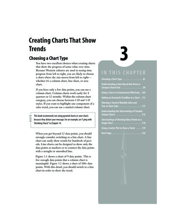
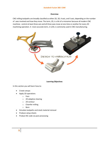
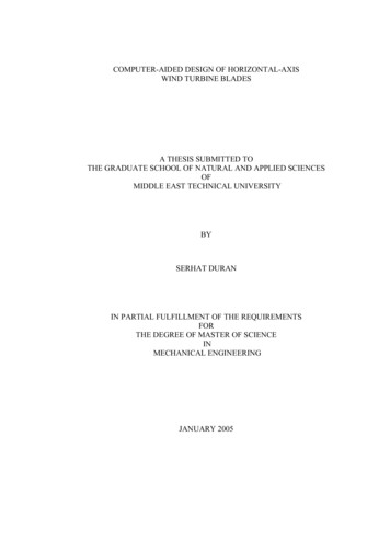
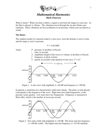
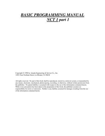
Design of a 5-Axis Holding FixtureAug 06 - May 07spindle , or Z axis, parallel to the A axis; and the B axis, which can be a rotary index tableor an additional tilting of the spindle parallel to the X axis.2The basic units of the machine provide the following movements: X Axis – Moving column assembly for longitudinal movement Y Axis – Moving carrier for vertical movement Z Axis – Moving pallet for cross movement A Axis – Contouring spindle for pivoting spindle about the X Axis B Axis – Contouring table for rotating work piece about the Y Axis A Axis – Rotary Spindle for Tool TiltFigure 2.1: The Axis Orientations on the Cincinnati T35The aspect of the machining center that this project is concerned with is the fixedbase unit. It consists of the front base (pallet support) and the rear base (column support)units which are bolted together and supported by adjustable leveling screws. These unitsform a “T” configuration which provides direct support for all horizontal (X and Z axes)movement. The front base supports the pallet slide and integrates the cross (Z Axis)movement by means of a precision ball screw drive. The rear base supports the column,2Madison. p. 7Worcester Polytechnic Institute3
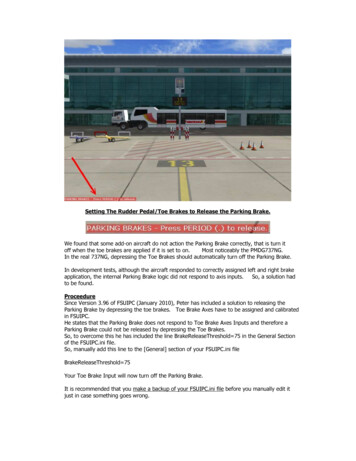
Design of a 5-Axis Holding FixtureAug 06 - May 07which is driven by a ball screw, in a direction perpendicular to the table movement toprovide longitudinal (X axis) movement.Figure 2.2: T-35 PalletThe machines, integrated with the control, comprises the system and is referred to asa machining center. The machining center has been designed to automatically changetools for milling, drilling, tapping, boring, and reaming; in fact, performs most types ofmachining operations, all in one handling of the work piece.Worcester Polytechnic Institute4
Design of a 5-Axis Holding FixtureAug 06 - May 072.2 Fixture DesignBefore designing a proper fixture, following concerns must be dealt with: “thenecessity of multiple fixtures owing to workpiece geometry complexity, the number ofworkpieces per fixture, the determination of suitable surfaces on the workpiece for locatingand clamping, and the sequence of work holding steps. The fixture configuration processwould yield the following information: Types of locators and clamps Positions of locators and clamps Clamping sequence and magnitudes of clamping forcesThe detailed designs (geometry, dimensions, and tolerances) of individual workholdingelements are determined by workpiece geometry, contact information (point, line, or planecontact between the locators and workpiece surfaces), expected frequency of utilization(e.g., batch production versus mass manufacturing), availibility of off-the-shelf standarddevice geometries, mode of operation (manual versus automatic), and finally conditions ofmanufacturing (clean-room versus machining with coolants)” (Benhabib 2003).2.2.1 The “5 steps of fixture design”By Ray Okolischan, Vice President, Carr Lane Manufacturing CoStep 1: Define RequirmentsDefine the problem that needs to be solved and the needs to be met.Questions that needs to be asked: Is the new tooling required for first-time production or to improve existing production? If improving an existing job, is the goal greater accuracy, faster cycle times, or both? Is the tooling intended for one part or an entire family of parts?Step 2: Gather/Analyze InformationCollect all relevant data and assemble it for evaluation. The main sources ofinformation are the part print, process sheets, and machine specifications. Keep goodWorcester Polytechnic Institute5
Design of a 5-Axis Holding FixtureAug 06 - May 07notes on all ideas, thoughts, observations, and any other data about the part or fixture forlater reference.4 things that need to be taken into consideration: Workpiece specifications – Size and shape of the part, accuracy required, properties of thepart material, locating and clamping surfaces, and the size of the run. Operation variables – type of operations required to make the part, number of operationsperformed, sequence of operations, inspection requirements, aand time restrictions. Availability of equipment - The tooling designer should verify what equipment will be used foreach operation. Typically, equipment criteria include the following factors: types and sizes ofmachines, inspection equipment, scheduling, cutting tools, and plant facilities. Personnel Considerations - Fixture designers should put themselves in the machineoperator's shoes and consider all the operational scenarios they can. Designers shouldconsider not only correct usage of the fixture, but also possible incorrect usage. They mustask, "Is there any way for me to hurt myself while operating this equipment?"Step 3: Develop Several OptionsThis phase of the fixture-design process requires the most creativity. A typicalworkpiece can be located and clamped several different ways. The natural tendency is tothink of one solution, then develop and refine it while blocking out other, perhaps bettersolutions. A designer should brainstorm for several good tooling alternatives, not justchoose one path right away.During this phase, the designer's goal should be adding options, not discarding them.In the interest of economy, alternative designs should be developed only far enough tomake sure they are feasible and to do a cost estimate.The designer usually starts with at least three options: permanent, modular, andgeneral-purpose workholding. Each of these options has many clamping and locatingoptions of its own. The more standard locating and clamping devices that a designer isfamiliar with, the more creative he can be.Worcester Polytechnic Institute6
Design of a 5-Axis Holding FixtureAug 06 - May 07Areas for locating a part include flat exterior surfaces (machined and unmachined),cylindrical and curved exterior surfaces, and internal features (such as holes and slots). Thechoice of standard locating devices is quite extensive.Similarly, there are countless ways to clamp a part, using a wide array of standardclamping devices. For example, a workpiece can be clamped from the top, or by grippingits outside edge or an internal surface.For preliminary drawings of the fixture, use several colored pencils. Often black isused to sketch the fixture, red for the part, and blue for the machine tool. Use isometricgraph paper to keep the sketch proportional.The exact procedure used to construct the preliminary design sketches is not asimportant as the items sketched. Generally, the preliminary sketch should start should startwith the part to be fixtured. The required locating and supporting elements, including abase, should be the next items added. Then sketch the clamping devices. Finally, add themachine tool and cutting tools. Sketching these items together helps identify any problemareas in the design of the complete fixture.Step 4: Choose the Best OptionThe fourth phase of the tool-design process is a cost/benefit analysis of differenttooling options. Some benefits, such as greater operator comfort and safety, are difficult toexpress in dollars but are still important. Other factors, such as tooling durability, aredifficult to estimate.In analyzing fixture costs, the emphasis is on comparing one method to another,rather than finding exact costs. Estimates are acceptable. Sometimes these methodscompare both proposed and existing fixtures, so that, where possible, actual productiondata can be used instead of estimates.To evaluate the cost of any workholding alternative, first estimate the initial cost of thefixture. To make this estimate, draw an accurate sketch of the fixture. Number and list eachWorcester Polytechnic Institute7
Design of a 5-Axis Holding FixtureAug 06 - May 07part and component of the fixture individually. Here it is important to have an orderlymethod for outlining this information.For modular fixtures, total component cost should be amortized over the system'stypical lifetime. Although somewhat arbitrary, dividing total component cost by 100 (10uses per year, for 10 years) gives a fair estimate.The next step is calculating the cost of material and labor for each tooling element.Once again it is important to have an orderly system for listing the data. First list the cost ofeach component, then itemize the operations needed to mount, machine, and assemblethat component. Once those steps are listed, estimate the time required for each operationfor each component, then multiply by the labor rate. This amount should then be added tothe cost of the components and of the design to find the estimated cost of the fixture.The total cost to manufacture a part is the sum of per-piece run cost, setup cost, andtooling cost. Expressed as a formula:These variables are described below with sample values from three tooling options: amodular fixture, a permanent fixture, and a hydraulically powered permanent fixture.Run Cost. This is the variable cost per piece to produce a part, at shop labor rate(material cost does not need to be included as long as it is the same for all fixturingoptions).In our example, run costs for the permanent and modular fixtures are the same, whilepower workholding lowers costs by improving cycle time and reducing scrap. Modular fixture: 4.50 Permanent fixture: 4.50 Permanent hydraulic fixture: 3.50Setup Cost. This is the cost to retrieve a fixture, set it up on the machine, and return itto storage after use. The permanent fixture is fastest to set up, the power workholdingWorcester Polytechnic Institute8
Design of a 5-Axis Holding FixtureAug 06 - May 07fixture is slightly slower due to hydraulic connections, and the modular fixture is slowestdue to the assembly required. Modular fixture: 240 Permanent fixture: 80 Permanent hydraulic fixture: 100Lot Size. This is the average quantity manufactured each time the fixture is set up. Inthis example, lot size is 100 for all three options.Tooling Cost. This is the total cost of labor plus material to design and build a fixture.The modular fixture is least expensive because components can be re-used. Modular fixture: 341 Permanent fixture: 1632 Permanent hydraulic fixture: 3350Total Quantity Over Tooling Lifetime. This quantity is the lesser of 1) total anticipatedproduction quantity and 2) the quantity that can be produced before the fixture wears out.The following results are obtained by evaluating the cost-per-part formula at differentlifetime quantities.For a one-time run of 100 pieces, the modular fixture is clearly the most economicalchoice. If 10 runs (1000 pieces) are expected, the permanent fixture is best. For 2500pieces and above, the power workholding fixture would be the best choice. This analysisassumes that all noneconomic factors are equal.PiecesModularPermanent100 10.31 21.62PermanentHydraulic .1710,0006.935.464.84Table 2.1: Run CostsWorcester Polytechnic Institute9
Design of a 5-Axis Holding FixtureAug 06 - May 07Step 5: Implement the Design:Use standard components. The economies of standardized parts apply to toolingcomponents as well as to manufactured products. Standard, readily available componentsinclude clamps, locators, supports, studs, nuts, pins, and a host of other elements.Most designers would never think of having the shop make cap screws, bolts, or nutsfor a fixture. Likewise, no standard tooling components should be made in-house. The firstrule of economic design is: Never build any component you can buy. Commerciallyavailable tooling components are manufactured in large quantities for much greatereconomy. In most cases, the cost of buying a component is less than 20% of the cost ofmaking it.Labor is usually the greatest cost element in the building of any fixture. Standardtooling components are one way to cut labor costs. Browse through catalogs andmagazines to find new products and application ideas to make designs simpler and lessexpensive.Use pre-finished materials. Pre-finished and preformed materials should be usedwhere possible to lower costs and simplify construction. These materials include precisionground flat stock, drill rod, structural sections, cast tooling sections, precast toolingbodies, tooling plates, and other standard preformed materials. Including these materials ina design both reduces the design time and lowers the labor cost.Eliminate finishing operations. Finishing operations should never be performed forcosmetic purposes. Making a fixture look better often can double its cost. Here are a fewsuggestions to keep in mind with regard to finishing operations. Machine only the areas important to the function and operation of the component. Forexample, do not machine the edges of a baseplate. Just remove the burrs. Harden only those areas of the fixture subject to wear. Grind only the areas of the fixture where necessary for operation.Worcester Polytechnic Institute10
Design of a 5-Axis Holding FixtureAug 06 - May 07Keep tolerances as liberal as possible. The most cost-effective tooling tolerancefor a locator is approximately 30% to 50% of the workpiece's tolerance. Tighter tolerancesnormally add extra cost to the tooling with little benefit to the process. Where necessary,tighter tolerances can be used, but tighter tolerances do not necessarily result in a betterfixture, only a more expensive one.Simplify tooling details. Elaborate designs often add little or nothing to the functionof the fixture. More often, a power clamp can do the same job at a fraction of the cost.Keep the function and operation of a fixture as simple as possible. The likelihood ofbreakdowns and other problems increases with complex designs. These problems multiplywhen moving parts are added to the design. Misalignment, inaccuracy, wear, andmalfunctions caused by chips and debris can cause many problems in the best fixturedesigns.Reducing design complexity also reduces misunderstandings between the designerand the machine operator. Whenever possible, a fixture's function and operation should beobvious to the operator without instructions.Once sketches and the basic fixture design have been completed, final engineeringdrawings, also called shop prints, are used in the toolroom to build the fixture.The easiest way to reduce manual drawing time is by simplifying the drawing. Wordsor symbols should be used in place of drawn details where practical. All extra orunnecessary views, projections, and details should be eliminated from the drawing.Drawing a complete clamp assembly, for example, adds very little to the total design.Simply showing the nose of the clamp, drawn in its proper relation to the workpiece andlabeled with its part number, conveys the same information in a fraction of the time.For drawings that require more detail, use tracing templates to reduce drawing time.These templates show most standard components in several views. If necessary, they maybe enlarged or reduced on a copier to any scale needed for a drawing.Worcester Polytechnic Institute11
Design of a 5-Axis Holding FixtureAug 06 - May 07Once the proper tracing template is selected, simply slip it under the drawing sheetand align it with the drawing. When the template is properly positioned, tape it down andtrace the component on the drawing sheet. Tracing templates save drawing time andimprove the quality of the drawing.Computers are rapidly replacing drawing boards as the preferred tool for preparingengineering drawings. Almost every area of design is affected by the computer.Computers, from large mainframes to micros, are becoming standard equipment in manydesign departments.A standard tooling library often is used to add the fixturing components and elementsto the drawing. Using a standard library in designing the fixture dramatically reducesdrawing time. All components are drawn to full scale in a variety of views. Scaling down isbest done in the final drawing, not when storing standard-component drawings. Storing alarge fixture base at 1/4 scale does little good, because all components will have to be 1/4scale to fit on it. For ease of use, all components should be stored at full scale. Eachcomponent can be called up from the library and placed on the drawing where it isrequired.A CAD system also can be useful during the initial phase of the workholder design asnumerous tooling options are developed. CAD is sometimes faster than sketching byhand, especially when detailed cost estimates are required.Once drawings have been thoroughly checked, the next step is actually building theactual fixture. During the building stage, the designer should make sure the toolroompersonnel know exactly what must be done when making the fixture. By periodicallychecking with the fixture builder, the designer can help eliminate any possiblemisunderstandings and speed the building process. If there are any difficulties with thedesign, the designer and builder, working together, can solve the problems with aminimum of lost time.Worcester Polytechnic Institute12
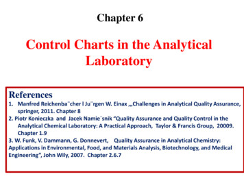
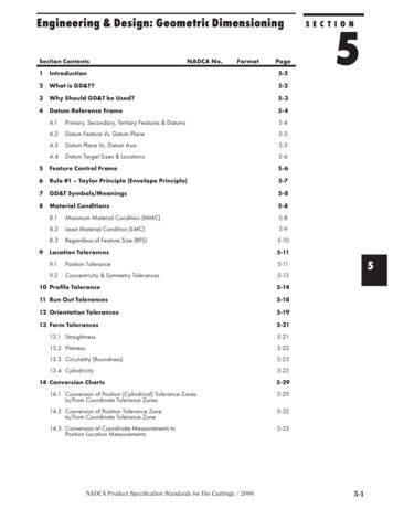
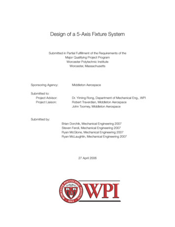
Design of a 5-Axis Holding FixtureAug 06 - May 07After the fixture is completed and inspected, it should be tested. The fixture is set upon the machine tool and several parts are run. The designer should be on hand to helpsolve any problems. When the fixture proves itself in this phase, it is ready for production.2.2.2 Work HoldingWork holding in manufacturing is the restriction of movement of a part or work piecefor the purpose of allowing a fabrication or application of an assembly process. A fixture isa “work holding device used in machining and assembly for securely locating and holdingthe work piece without providing a built-in guidance to the manufacturing tool. Fixtures,must provide maximum accuracy (including measures to prevent incorrect work holding)and be designed for ease of mounting and clamping of the work piece by humans orrobots” (Benhabib 2003).Design of a fixture requires the examination of the work piece’s geometry, thefabrication processes, and the specific machines to be used. The work piece’s geometryincludes the material, mechanical properties, and tolerances of the work piece. Thefabrication process involves the tool paths, machining and/or assembly forces, and theenvironment containing the work piece. The fixture must be able to hold the work piece inplace while it is subjected to external forces (Benhabib 2003).2.2.3 LocatingA solid body has twelve degrees of freedom (DOF) of mobility in three-dimensionalfree space: six degrees of linear movement freedom along the X, Y and Z axes and six ofrotational freedom along the X, Y and Z axes. The goal of a fixture is to “eliminate allmobility and simultaneously provide adequate support to the workpiece to counteractexternal forces” (Benhabib 2003).The principle rule of locating a workpiece is the 3-2-1 rule. The use of six locators isenough to fully restrict a workpiece’s degrees of freedom. The first location restricted isthe largest plane of the workpiece, also know as the primary plane. Three locators areplaced on this plane restricting X and Y rotational and Z linear motion. The second largestWorcester Polytechnic Institute13
Design of a 5-Axis Holding FixtureAug 06 - May 07surface, the secondary plane requires two locators eliminating Z rotational and X linearmotion. The final locator is used on the smallest surface restricting Y linear motion. Theremaining degrees of freedom can be restricted by a clamping device (Drozda 1989),(Benhabib 2003).Figure 2.3: Degrees of Freedom & 3-2-1 RuleFor the better accuracy, locators should make contact with machined parts of theworkpiece. This is not always possible and placement of the locators is determined by theworkpieces’s stress analysis. Locators may be placed on the edge, underneath or inexisting holes on the workpiece. (Boyes 1985)2.3 Part Holding MethodsOne of the major areas to consider when completing a fixture design is the method inwhich the part is held. The fixture design will specify where the part can be held, but thencare needs to be taken as to the choice of the type of holding. There are varying was ofpart holding, and each has it own benefits and drawbacks. The choice of holdingmethods depends on many factors including but not limited to tolerances, part material,forces on the part, and the fixture design itself.2.3.1 BoltingBolting to the machine table is the simplest and most basic way to hold a fixture orworkpiece in place. Most machine tables have sets of channels cut into them that act asWorcester Polytechnic Institute14
Design of a 5-Axis Holding FixtureAug 06 - May 07guides for the bolts and braces to hold the bolts in place. When a part/fixture is securedusing the bolting method the machine operator places the piece on the table and runs thebolts through the holes on the workpiece/fixture. Then once the piece is in place theoperator tightens the nuts onto the bolts with a wrench.2.3.2 ClampingThe clamping method uses vises and clamps to hold the workpiece/fixture. Theclamps are usually
Horizontal CNC Machining Centers, a Cincinnati T35 and a Mitsui Seiki HU-80. Five axis controls provide multiple axis-machining capabilities beyond the standard three-axis CNC toolpath movements. The simultaneous contouring axes of a five-axes milling center include the three X, Y,