Transcription
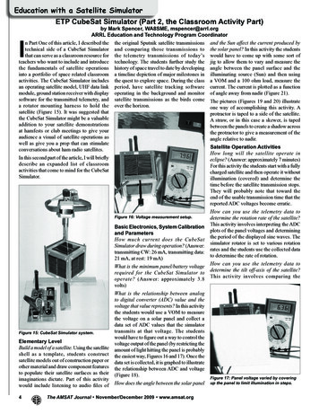
Education with a Satellite SimulatorETP CubeSat Simulator (Part 2, the Classroom Activity Part)by Mark Spencer, WA8SME, mspencer@arrl.orgARRL Education and Technology Program Coordinatorn Part One of this article, I described the the original Sputnik satellite transmissions and the Sun affect the current produced bytechnical side of a CubeSat Simulator and comparing those transmissions to the solar panel? In this activity the studentsthat can serve as a classroom resource for the telemetry transmissions of today’s would have to come up with some sort ofteachers who want to include and introduce technology. The students further study the jig to allow them to vary and measure thethe fundamentals of satellite operations history of space travel to date by developing angle between the panel surface and theinto a portfolio of space related classroom a timeline depiction of major milestones in illuminating source (Sun) and then usingactivities. The CubeSat Simulator includes the quest to explore space. During the class a VOM and a 100 ohm load, measure thean operating satellite model, UHF data link period, have satellite tracking software current. The current is plotted as a functionmodule, ground station receiver with display operating in the background and monitor of angle away from nadir (Figure 21).software for the transmitted telemetry, and satellite transmissions as the birds come The pictures (Figures 19 and 20) illustratea rotator mounting harness to hold the over the horizon.one way of accomplishing this activity. Asatellite (Figure 15). It was suggested thatprotractor is taped to a side of the satellite.the CubeSat Simulator might be a valuableA straw, or in this case a skewer, is tapedaddition to your satellite demonstrationsbetween the panels to create a shadow acrossat hamfests or club meetings to give yourthe protractor to give a measurement of theaudience a visual of satellite operations asangle relative to nadir.well as give you a prop that can stimulateSatellite Operation Activitiesconversations about ham radio satellites.How long will the satellite operate inIn this second part of the article, I will brieflyeclipse? (Answer: approximately 7 minutes)describe an expanded list of classroomFor this activity the students start with a fullyactivities that come to mind for the CubeSatcharged satellite and then operate it withoutSimulator.illumination (covered) and determine thetime before the satellite transmission stops.They will probably note that toward theend of the usable transmission time that thereported ADC voltages become erratic.IFigure 16: Voltage measurement setup.Basic Electronics, System Calibrationand ParametersHow much current does the CubeSatSimulator draw during operation? (Answer:transmitting CW: 26 mA, transmitting data:21 mA, at rest: 19 mA)What is the minimum panel/battery voltagerequired for the CubeSat Simulator tooperate? (Answer: approximately 3.8volts)Figure 15: CubeSat Simulator system.Elementary LevelBuild a model of a satellite. Using the satelliteshell as a template, students constructsatellite models out of construction paper orother material and draw component featuresto populate their satellite surfaces as theirimaginations dictate. Part of this activitywould include listening to audio files of4What is the relationship between analogto digital converter (ADC) value and thevoltage that value represents? In this activitythe students would use a VOM to measurethe voltage on a solar panel and collect adata set of ADC values that the simulatortransmits at that voltage. The studentswould have to figure out a way to control thevoltage output of the panel (by restricting theamount of light hitting the panel is probablythe easiest way, Figures 16 and 17). Once thedata set is collected, it is graphed to illustratethe relationship between ADC and voltage(Figure 18).How does the angle between the solar panelThe AMSAT Journal November/December 2009 www.amsat.orgHow can you use the telemetry data todetermine the rotation rate of the satellite?This activity involves interpreting the ADCplots of the panel voltages and determiningthe period of the displayed sine waves. Thesimulator rotator is set to various rotationrates and the students use the collected datato determine the rate of rotation.How can you use the telemetry data todetermine the tilt off-axis of the satellite?This activity involves comparing theFigure 17: Panel voltage varied by coveringup the panel to limit illumination in steps.
comparing the resulting graphs, the reducedrate down to 4 seconds still produces a fairrepresentation of the sine wave, but at theslower rate of 7.5 seconds (just below theNyquist rate) the graph begins to show signsof distortion, and at the rates of 12 and 16seconds, the graphs show a sine wave thatis totally different than what is actuallyhappening. This illustrates the concept ofaliasing that results from an insufficientsampling rate (a common problem that mustbe dealt with in DSP).ADC vs Panel Voltage1000ADC Value8006004002000012345678VoltageFigure 18: Excel generated graph of voltage vs. ADC value.collected Z axis data when the satellite isvertical versus when tilted in the harness.When vertical, the Z axis data is virtuallyflat indicating a constant angle between theZ axis panels and the illumination source.When tilted off nadir, the angle between theZ axis panels and the illumination sourcevaries with the characteristic sine curve. Amore advanced exploration would be to usethe data to quantify the angle of tilt.How can you use the telemetry data totroubleshoot a problem with the satellite,for instance, a degraded solar panel? In thisactivity one of the solar panels is degradedto simulate a problem, in the example here,the panel is simply covered up temporarily.Using the collected data, the studentsdetermine what the problem might be andcan speculate possible solutions.What is the minimum number of data pointsneeded to get an accurate picture of theparameter being measured? This activity isactually exploring some concepts borrowedfrom digital signal processing techniques;the Nyquist frequency or rate and aliasing.Figure 19: Current measurement setup.There is significant power consumed bythe satellite to transmit the telemetry data,and it is prudent to limit the amount of datatransmitted to the minimum rate requiredto send accurate information to conservingpower for other purposes. To obtain accurateinformation about a waveform (in thiscase the voltage produced by solar panelson a rotating satellite), the waveformmust be sampled at a rate of at least twicethe frequency of the wave (the Nyquistfrequency). The waveform produced bythe panels in the simulator is a nice smoothsine wave therefore we should be able tosample the panels at a minimum rate of twicethe rotation rate of the satellite and still beable to recover the information about thewaveform without degradation. Samplingthe waveform at a high rate will producedmore detailed information, but in many casesthe added information would be redundantand power wasteful.In this activity, the satellite is rotated at 4rpm and data collected over a number ofminutes to produce a data set of sufficientsize. The CubeSat Simulator is programmedto send data points every second. To simulatereducing the collection rate, data pointsare simply thrown out and the remainingdata is graphed to see if there remains anaccurate representation of the full data set.The Nyquist rate for a satellite rotatingat 4 rpm would dictate that 8 samples perminute be collected (twice the rotation rateof the satellite) or data points every 60/8 7.5 seconds. In Figure 27, the data rate isreduced in steps by throwing out data pointsto simulate collection rates of every 1 second(the default raw data rate), 4 seconds, 7.5seconds, 12 seconds, and 16 seconds. InThis activity illustrates that care must betaken when interpreting telemetry data. Sofor the CubeSat Simulator rotating at 4 rpm,the data rate can be reduced to around 6seconds between points to conserve powerwithout reducing the information that can begleaned from the data, however rates lowerthan that, while further more conservingpower, will corrupt the data. This situationwould be evident if the students collect thedata using the Morse code telemetry modewhich is sending data at a rate far below theminimum Nyquist rate.Figure 20: Current measurement angleadjustment setup.Conclusion Part 2I envision that the CubeSat Simulator willprove to be a valuable resource that teachers(and hams) can use to help their studentsto better understand the fundamentals ofsatellite operations so the students canbetter appreciate satellite technology thatour society is becoming ever-increasinglydependent upon, and want to learn moreabout space borne assets at an advancedlevel. Perhaps the CubeSat Simulator willstimulate your fellow ham radio operatorsto want to “see you on the birds.” Foradditional information about the CubeSatSimulator, or any of the other ETP projectsand resources, contact Mark Spencer,WA8SME, at mspencer@arrl.org or 530495-9150 (Pacific Time Zone).Figures continue on the next 3 pages .The AMSAT Journal November/December 2009 www.amsat.org5
Panel Current and Power vs Angle800.5700.45Current in mA0.35500.3400.25300.20.1520Power in Watts0.460Current mAI 2R0.1100.05006050403020100-10 -20 -30 -40 -50Degrees from NadirFigure 21: Excel generated graph of angle vs. current.X Axis ADCSatellite X Axis Solar Panel 4603470348034903500Figure 23: Tilt the satellite at various anglesfrom nadir.3510Tim e in SecondsX Axis ADCSatellite X Axis Solar Panel 090100110120Tim e in SecondsFigures 22-1 and 22-2: Excel generated graphs of rotation rates of 4 and 2 rpm.Measuring periods gives insight into rotation rate.6The AMSAT Journal November/December 2009 www.amsat.orgFigure 25: Degrade panel by covering it withan opaque paper.
Apogee View - continued from page 3 .on spacecraft experience for engineeringstudents.Satellite Z Axis Solar Panel Output1000Z Axis ADC800600Z 400Z-20001040105010601070108010901100Tm e in SecondsSatellite Z Axis Solar Panel Output1000Z Axis 12901300Tm e in SecondsFigures 24-1 and 24-2: Excel generated graphs of data from nadir to some off-axistilt. The Z-axis panels pick up sinusoidal characteristics.Satellite X Axis Solar Panel OutputX Axis 181018201830Tim e in SecondsFigures 26-1 (above) and 26-2 (next page): The problem with one of the panels isevident by comparing data plots.Moving forward . AMSAT continuesto deal with ITAR. Our four commodityjurisdiction requests that were submitted tothe State Department last July to transferexport control of those subsystems thatAMSAT was developing for Phase 3-E(and eventual placement into Eagle) to theCommerce Department were denied. Again,AMSAT is left with no clear guidance on whatconstitutes appropriate behavior regardingdevelopment of spacecraft systems in anopen source public domain environment thatAMSAT has always followed. Consequently,we submitted an Advisory Opinion requestto the Directorate of Defense Trade Controls(DDTC) on December 4th asking specificquestions regarding AMSAT’s activities andwhether the steps we are taking in publicdomain will allow us to openly exchangetechnical information with AMSAT-DLand AMSAT-UK. Without such guidance,AMSAT is left with very restrictive optionsfor working on international satellite projectswith other AMSAT organizations.AMSAT has spent a significant amount ofmoney on legal fees on both ITAR and theclean room litigation. While it has been verydisappointing that we’re spending money onattorneys and the regulatory process ratherthan building hardware, this is money thathas been well spent given the environmentin which we’ve found ourselves. We at leasthave resolved the legal issues regardingpast ITAR activities with P3-E and freedourselves from a disappointing relationshipwith UMES/HISS. Again, we’re nowin position to move forward rather thancontinue to deal with past concerns.Moving forward NASA has informedAMSAT that the schedule of work forEVAs at the International Space Stationis being revised. The planned deploymentof ARISSat-1 from the ISS is now beingscheduled for either Fall 2010 or early 2011rather than Spring 2010. This scheduleadjustment also impacts when ARISSat-1will be flown to the Space Station with uploadlikely to take place sometime in summer2010 rather than in January. These revisionswere made in response to new higher priorityISS work that must be done during the EVAthat ARISSat-1 was originally scheduled todeploy in April 2010.continued on page 19 .The AMSAT Journal November/December 2009 www.amsat.org7
Satellite X Axis Solar Panel OutputX Axis 205020602070Tim e in SecondsFigure 26-2 (above): The problem with one of the panels is evident by comparingdata plots.Figure 27: Simulate data collection rate reductions by “throwing out” data points. At rates just above the Nyquist rate, the data looks right;at or ferent.Reducing t 8The AMSAT Journal November/December 2009 www.amsat.org
Satellite Z Axis Solar Panel Output 0 200 400 600 800 1000 1040 1050 1060 1070 1080 1090 1100 Tme in Seconds Z Axis ADC Z Z-Satellite Z Axis Solar Panel Output 0 200 400 600 800 1000 1240 1250 1260 1270 1280 1290 1300 Tme in Seconds Z Axis ADC Series5 Series6 Figures 24-1 and 24-2: Excel generated graphs of data from nadir to some off-axis tilt.