Transcription
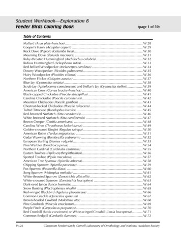
150 Series DrawoutMotor (MVD) and Feeder (FVD) Protection RelaysIntelligent Protection and ControlField programmable frontpanel, including LEDs anddisplay.Support for Ethernet,IEC 61850, MODBUSTCP/IP. Serial,MODBUS RTU, P&BNetwork Gold andPROFIBUS DP.Withdrawable case structurefeaturing self shorting CTcontacts on removal.Simple and Easy to usemenu interfaceComprehensive Protectionfor MV and LV systemsDesigned for high temperature 75 years experience of providingindustrial environmentsworld class protection productsP&B Protection Relays – Vision Range of Intelligent Protection and Control Products
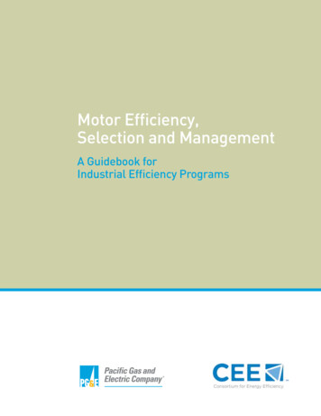
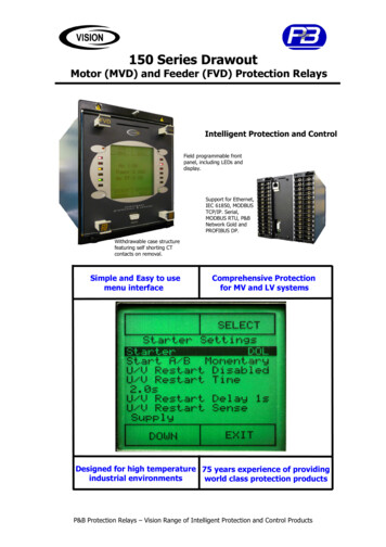
Functional OverviewThe MVD and FVD protection relays provide many functions, these include multiplecommunication options, a range of I/O configurations including programmable externalinputs, trip circuit supervision protection, programmable outputs and configurable LEDsmaking the 150 Series relays a complete solution for MV and LV applications.SerialEthernetDistributedControl SystemEngineering WorkstationDigital Inputs* Feeder ProtectionDigital/RelayOutputs* Motor ProtectionSerialTransformerFeederTCSMotorPC Relay ProgrammingSoftwareTrip Circuit Supervision Protection(* Dependent on relay type chosen)Hardware Overview Operating temperature range -20 C to 85 CAuxiliary power supply voltage range 80 – 265Vac/dc or 24 - 48Vdc1A or 5A ac current inputs I1, I2, I3 and I0500Vac maximum ac voltage inputs V1, V2, V3 and V0Twelve programmable digital inputsUpto three programmable relay outputs with changeover contactsUpto seven programmable LED status indicatorsTwo channel trip circuit supervision protectionRS232 programming portSerial RS485 or Ethernet communication128 x 128 graphic liquid crystal displayTime Synchronsiation – Serial and NTPOptional conformally coated circuit boardsP&B Protection Relays – Vision Range of Intelligent Protection and Control Products
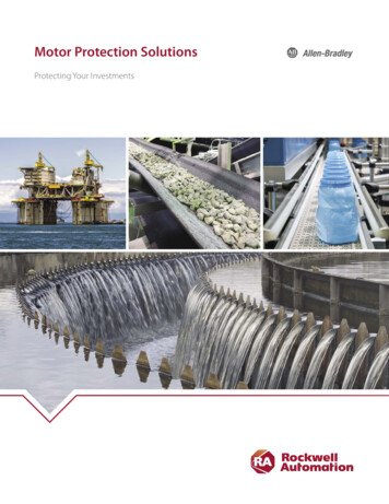
Protection OverviewUUVoltage InputsV1, V2 and V3 *Optional NeutralVoltage Vo Two Channel TripCircuit MonitorMVD Motor Protection Relay 32 Event Alarm and Trip History,Last 5 fault with trip data.275986U81 OUndervoltageOvervoltageUV verpowerPower FactorUUUCurrent InputsI1, I2 and I3Trip CircuitSupervision49ThermalOverloadUU Programmable Front Panel LEDs Trip Circuit Supervision* Smart Card (settings/data) 128x128 Large Graphical LCD471966PhaseRotationStart ProtectionStarts Per Hour50BF5146OvercurrentShort CircuitBreaker FailOvercurrent/Stall Single PhasingLoad Increase Phase UnbalanceCurrent Input I050/51NCommunicationsModuleEarth FaultMotor 1mS Time & Date Stamping Ethernet Communication Port**TCM Disturbance Recorder 148674Speed SwitchSerial InhibitSerial Timeout Multiple Motor StarterConfigurations supported, suchas DOL, Two-Speed, Star/Deltaand others. Instantaneous Metering Serial Communication Ports 10 x Programmable ExternalInputs with Custom Strings IEC61850*, MODBUS TCP/IP*,MODBUS RTU, P&B Gold andPROFIBUS* Statistical and Historical Info. Display Mimic showing breakerMotor Status* Optional FunctionsUUFVD Feeder Protection Relay 32 Event Alarm and Trip History,Last 5 fault with trip data.Voltage InputsV1, V2 and V3 275981 onal NeutralVoltage Vo Programmable Front Panel LEDsCommunicationsModuleOvervoltage Trip Circuit Supervision* Smart Card (settings/data) 128x128 Large Graphical LCDTwo Channel TripCircuit Monitor52 1mS Time & Date Stamping Ethernet Communication Port**59NBreaker Disturbance Recorder Breaker Wear Monitor74*TCM Peak Demand MeteringSerial Timeout Instantaneous MeteringTrip CircuitSupervisionUU Current Input I0Current InputsI1, I2 and I3UUU Serial Communication Ports50/51N#50/51N*67NEarth Fault 1EF 2 HSEarth Fault 2EF 2 HSDirectionalEarth Fault505150BFOvercurrent LS Overcurrent 1Overcurrent HS Overcurrent 2Load IncreaseBreaker Fail 12 x Programmable ExternalInputs with Custom Strings IEC61850*, MODBUS TCP/IP*,MODBUS RTU, P&B Gold andPROFIBUS* Statistical and Historical Info.79AutoReclosing Display Mimic showing breakerStatus* Optional Functions# Dependent on software config.P&B Protection Relays – Vision Range of Intelligent Protection and Control Products
Feature OverviewLarge 128 x 128 graphicliquid crystal display.Provides clear conciseinformation, multiplemessages can be viewedalong with detailedfault/troubling shootingdata, such asdisturbance recordingdata and motor startcurveSmartcard interface port,allowing externalSettings/Data storageEasy to use four buttonmenu interfaceRS232 port allowingsimple programming anddata extraction from therelay via a PC.Programmable frontpanel LEDs to indicateuser defined relay statusOptional Ethernetcommunication port,MODBUS TCP/IP orIEC 61850Power supply options80 – 265Vac/dcand 24 - 48VdcProgrammable digitalinputs, with editablecustom string optionsFour programmableoutput relays withchangeover contactsOptional two channelTrip Circuit Supervision(TCS) monitorHigh speed RS485 serialcommunication portCT inputs, 3 phase Earth fault. CT inputshave self shortingcontacts, whichengage when relay isremoved from thecase.VT inputs, 3 phase optional neutralvoltage inputAll connectors are equipped for bothscrew and crimp terminalsOptional IEC 61850programming/upgradeport interfaceP&B Protection Relays – Vision Range of Intelligent Protection and Control Products
User Interface and ProgrammingThe LCD menu is driven by four push buttons, this allows access to measured and recordeddata as well as providing a programming interface for the relay settings. The large displayallows the menu to be structured in an intuitive way to allow ease of use and clearunderstanding of the presented information.The 150 Series Drawout relays provide three ways to quickly and easily configure theprotection and systems settings required to put the relay into service. One method is via thelarge liquid crystal display using the simple and intuitive menu structure, the second methodis via a personal computer and the P&B dedicated Vision Control software and the thirdmethod is via a portable smartcard.Vision Control SoftwareThe Vision Control software is a Windows based PC program offering a graphical userinterface allowing full access to the P&B Vision relays, key features are shown below. Designed to allow online/offline programming of all P&B Vision RelaysOne parameter file can store data for upto 32 devices as per a typical RS485 networkSingle drives or complete networks are supported, there is no limit on the number ofParameter files, which can be used/saved.Metering and Historic data is readily available for download/viewingDisturbance Recording data extraction (COMTRADE format)Support for relay firmware updatesSupport for Smartcard programmingP&B Protection Relays – Vision Range of Intelligent Protection and Control Products
Fault Reporting and TroubleshootingThe 150 Series relay comes equipped with an extensive range of features designed to helpand determine the order and cause of events, to aid and assist in troubleshooting and rootcause analysis. All events and waveforms captured are time and date stamped with aresolution of 1mS.Disturbance Recorder OverviewDisturbance and fault recording is a very effective tool for the operating and design personnelto analyse the performance of the power system and related equipment during and after amajor disturbance.P&B’s Disturbance and Fault Recorder System acquires the conditions in an electrical systemthat lead to (pre-fault), persist during (fault) and follow the fault (post-fault) for subsequentanalysis. The analysis provides a detailed insight, with time resolution in milliseconds, into thebehaviour of the electrical system.Each relay can be equipped with its own onboard disturbance recording facility. This canprovide up to 8 seconds of waveform capture and can be multi triggered and weighted preand post fault. Each current and voltage phase is individually recorded along with oneprogrammable digital input and one programmable digital output. Uniquely, due to thepowerful graphical display, waveform traces can also be viewed directly at the relay withzoom and scroll functions without the need for any external equipment. Alternatively thewaveform data maybe extracted from the relay using the front RS232 port in a ‘COMTRADE’format for analysis by any compatible software.For motor protection the disturbance recorder can be set to trigger on a motor start, thisallows a complete capture of the motor start event providing a graphical capture of the actualwaveforms allowing the user to easily troubleshoot any problems with motor starting.Fault Event OverviewThis allows upto 32 trip and 32 alarm events to be recorded all with time and date stamping,with a resolution of 1mS. The last 5 events, both for trip and alarm come complete with allthe pre-trip data, this includes all current and voltage values, power, power factor and anyother relevant data associated with the trip or alarm.The event recorder memory capacity can be increased through the use of an externalsmartcard. Through the use of the smartcard sequence event records can be recorded. Thisallows the tracking of control inputs, control outputs, command inputs, trip/alarm events andauxiliary power dips/losses. The time and date of each event are available in the report.P&B Protection Relays – Vision Range of Intelligent Protection and Control Products
SpecificationsAuxiliary Power Supply & Low Voltage Power SupplyAC NominalMaximum Power ConsumptionRange 80 – 265V AC / DCRange 24V AC / 24-48V DC (Low Voltage Power Supply Optional Extra)10VA NominalOperating Temperature Range150 Series Protection Relay-20 C to 85 CIEC 61850 Communication Card-40 C to 85 CPhase Current MeasurementMethodRangeFull ScaleDisplay AccuracyPick Up AccuracyTrue RMS, Sample time 1ms0.1 to 25x Phase CT Primary Amps25 x Phase CT Primary Amps Setting 3% at Phase CT Primary amps 3% of settingEarth Phase Current MeasurementMethodRangeFull ScaleDisplay AccuracyPick Up AccuracyCT BurdenTrue RMS, Sample time 1ms0.01 to 2.5x E/F CT Primary Amps (MVD)0.10 to 25x E/F CT Primary Amps (FVD)2.5 x E/F CT Primary Amps Setting (MVD)25 x E/F CT Primary Amps Setting (FVD) 3% of Reading Over Range 3% of setting0.1VAVoltage Reference MeasurementSuitable for connection preferably via isolating transformers (VT) or direct connection to max phase to phase systemvoltage not exceeding the rated voltage.MethodRated Insulation VoltageRangeDisplay AccuracyTrue RMS, Sample time 1ms1000V100 – 500V AC up to 22kV with external VT 3%Power AccuracyVT Burden 5% of Nominal0.01 VAOverload Alarm and Trip CurvesFault Time AccuracyThreshold Current Level 50mS up to 10 seconds 2% of trip time over 10 secondsOverload Setting 2%Current Unbalance Alarm and TripMethodAlarm Threshold Unbalance LevelAlarm Fixed Time Delay AccuracyTrip Threshold Unbalance LevelTrip Time AccuracyUnbalance 100 x (Imax - Imin) / Ir %Where Imax max. of 3 phase currentsImin min. of 3 phase currentsIr Larger of Imax or Motor FLC50% of Unbalance current 2%1.0 0.1 secondsUnbalance Current Setting 2% 0.1 second up to 10 seconds 0.1 second /- 2% above 10 sec.Time DelaysAccuracyExceptionsEarth Fault TripTotal Run TimeAuto Restart delay on Restart Time 0.5 seconds or 2% of time 150mS,-0.0@ 1.1 x setting 60mS,-0.0@ 2 x setting 40mS,-0.0@ 5 x settingAccuracy 2% 0.2 seconds ( additional 2 second initialisation time delay if aux. supply lost)Output RelaysRated Load(at various supply voltages)Continuous Thermal LoadMax Making Current (max. 4s at duty cycle 10%)Bounce time N/O contact / N/C contactContact Protection10A @ 250 AC10A @ 30V DC0.6A @ 110V DC0.1A @ 220V DC10A35A0.6 / 17 ms385V DC, 47 J MOV across both normally closed and normally open contactsP&B Protection Relays – Vision Range of Intelligent Protection and Control Products
Application OverviewMVD Typical Application150 Series Terminal ConnectionsLIVE12NEUTRALDigital Input 32930 Digital Input 4Relay 1 NC34Relay 2 NCDigital Input 53132Digital Input 6Relay 1 C56Relay 2 CDigital Input 73334Digital Input 8Relay 1 NO78Relay 2 NODigital Input 93536Digital Input 10Relay 3 NC910Relay 4 NCDigital Input 11 3738Digital Input 12Relay 3 C1112Relay 4 CTCS 1 3940TCS 2 TCS 1-4142TCS 2-TCS O/P 1 NC 4344TCS O/P 2 NCTCS O/P 2 CRelay 3 NO1314Relay 4 NO485 1516485 -485 Gnd1718EARTHTCS O/P 1 C4546Digital Input 11920Digital Input 2TCS O/P 1 NO 4748TSC O/P 2 NOI1 High2122I1 LowV1/I4 High 4950V1/I4 LowI2 High2324I2 LowV2/I5 High 5152V2/I5 LowI3 High2526I3 LowV3/I6 High 5354V3/I6 LowIo High2728Io LowVref High 5556Vref LowP&B Protection Relays – Vision Range of Intelligent Protection and Control Products
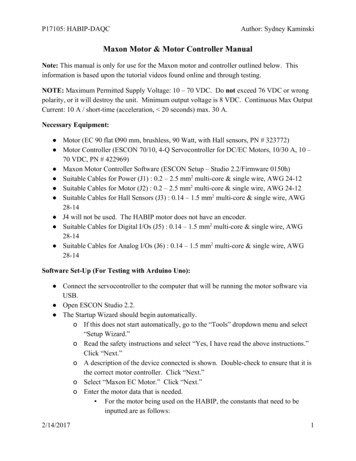
FVD Typical ApplicationP&B Protection Relays – Vision Range of Intelligent Protection and Control Products
178.00 mm156.00 mm150.00 mm127.00 mm23.00 mmDesigners and Manufacturers ofMotor and Feeder IntegratedProtection Control & MonitoringSystems168.00 mm158.00 mmP&B Protection Relays,Belle Vue Works, BoundaryStreet, ManchesterM12 5NGUKTel: 44 (0)161 230 6363Fax: 44 (0)161 230 6464http:www.pbeng.co.ukmail@pbeng.co.uk104.00 mmø 4.30 mmEnclosure Cut Out DimensionsP&B Protection Relays – Vision Range of Intelligent Protection and Control Products
*59N Ove rvoltag e 52 Breaker U27 *59N *Optional Neutral Voltage Vo rvoltage Earth Fault 1 EF 2 HS TCM Trip Circuit Supervision 59 81 O Ove rvoltage Frequency U U 50/51 N *67 N Earth Fault Current Input I0 U U Current Inputs I1, I2 and I3 50 Overcurrent LS Overcurrent HS Load Increase # 50/51 Earth Fault 2 EF 2 HS 95 Overpower 51 Overcurrent 1