Transcription
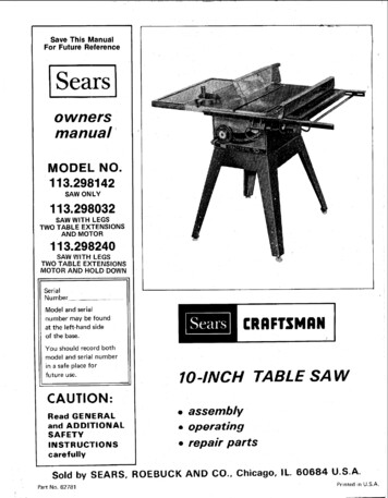
Save This ManualFor Future ReferenceISearsownersmanual*MODEL NO.113.298142SAW ON LY113,298032SAW WITH LEGSTWO TABLE EXTENSIONSAND MOTOR113.298240SAW WITH LEGSTWO TABLE EXTEN SIONSMOTOR AND HOLD DOWNSerialNumberModel and serianumber may be foundat the left-hand sideof the base.You shouldrecord bothmodel and serial numberin a safe place forfuture use.10-INCHTABLE SAWCAUTION: assemblyRead GENERALand ADDITIONALSAFETY. operating repairINSTRUCTIONSpartscarefullySold by SEARS,Part No. 62781ROEBUCKANDCO.,Chicago,IL. 60684U.S.A.Printedn U.S.A.
FULL ONE YEAR WARRANTYIf daterepairof purchase,thisit, free of charge.WARRANTYSERVICEIS AVAILABLECENTER/DEPARTMENTTHROUGHOUTON CRAFTSMANCraftsmanThis warrantyTableappliesSawTABLEfailsonly whileBY SIMPLYCONTACTINGTHE UNITED STATES duetoSAWa defectthis productTHEin materialoris in use in the UnitedNEARESTSEARSSERVICEThis warranty gives you specific legal rights, and you may also have other rights which vary from state to state.SEARS, ROEBUCK AND CO., Dept. 698/781A.Sears Tower, Chicago, I L 60684GENERAL SAFETY INSTRUCTIONSFOR POWER TOOLS1. KNOW YOUR POWER he owner'smanualandlabelsthetoolLearnits applicationandas well as the specificpotentialhazardsto this tool.2. GROUNDALL TOOLSThis tool is equippedwith an approveo3*conductorcord and a 3-pronggroundingtype plug to fit theproper groundingtvpe receptacle.The green conductorin the cord is the groundingwire. Never connect thegreen wire to a live terminal.3. KEEP GUARDSin workingalignment.IN PLACEorder,andin4. REMOVE ADJUSTINGAND ndnot be slippery6. AVOIDCLEANbenchesinviteaccidents,Floordue to wax or sawdust.DANGEROUSAll visitorsarea,should8. MAKE WORKSHOP-- withpadlocks,starter keys.9. ORCE TOOLIt will do the job betterit web dc igncd.10. USE RIGHTor attachmentto do a job it was not11. WEAR PROPER APPARELGOGGLESKeep properfooting15. MAINTAINand balanceat all times.TOOLS WITH CAREKeeptoolssharpand cleanperformance,Followinstructionschanging accessories.beforeblades,17. RTINGis in "OFF"owner'sthe accessories.cause hazards.Seriouscuttingbest andlubricatingforchangingACCIDENTALsure switchaccessories.forTOOLSservicing;whenbits, cutters, etc.forrecommendedinstructionsuse ofthatimproperaccompanyaccessoriesmayON TOOLinjury could occur if the tooltool is accidentallycontacted.is tippedor if theDo not store materials above or near the tool such thatit is necessary to stand on the tool to reach them.BeforefurtherCheckparts,PARTSuse of the tool,for alignmentbreakageofconditionsDo not wear loose clothing, gloves, neckties or jewelry(rings, wrist watches) to get caught in moving parts.Nonslipfootwearis recommended.Wear protectivehair covering to containlong hair. Roll long sleevesabove the elbow.12. USE SAFETYofa guardor otherpart thatis damaged should be carefullychecked to ensure that itwill operate properlyand performits intended function.TOOLDon't force tooldesigned for.periods14. DON'T OVERREACH20. CHECK DAMAGEDand safer at the rate for whichextendedUse clamps or a vise to hold work when practical.It'ssafer than using your hand, frees both hands to operatetool.19. NEVERa safe distanceduring13. SECURE WORKConsultAWAYbe keptor muffs)18. USE RECOMMENDEDENVIRONMENTDon'tuse power tools in damp or wet locationsorexpose themto rain. Keep workarea well lighted.Provide adequate surroundingwork space.7. KEEP CHILDREN(plugs 16. DISCONNECTForm habit of checkingto see that keys and adjustingwrenchesare removedfrom tool before turningit on.5. KEEP WORK AREAprotectorsopera ion(Head Protection)Wear Safety goggles (must complywith ANSI Z87.1)at all times.Everydayeyeglasses only have impactresistantlenses, they are NOT safety glasses. Also, useface or dust mask if cutting operationis dusty, and earthatother part thator replaced.21. DIRECTIONFeed workof rotationmayitsbinding of movingand anyotheroperation.shouldAbe properlyguardorrepairedOF FEEDinto a blade or cutter againstof the blade or cutter only.powercomplete'affectis damaged22. NEVER LEAVEUNATTENDEDTurnof moving nRUNNINGleavetooluntilit comesto a
CTIONS.AND UNDERSTAND1.SAFETYYOUROWNSAFETY,DONOTSAWUNTILIT IS COMPLETELYINSTALLEDACCORDINGTO THEANDUNTILYOUHAVEREADTHE FOLLOWING.2.GENERALTOOLS.GETTING3.4.5.6.BASIC SAW OPERATION. . . SEE PAGEADJUSTMENTS. . . SEE PAGE 29MAINTENANCE.SEE PAGE 34STABILITYOF SAWIf thereINSTRUCTIONSSAFETYINSTRUCTIONSSEE PAGE 2TO KNOW YOUR SAW .is any tendencyFOR(sawing entirelythruall loose pieces fromwood IMMEDIATELY20E.23for the saw to tip over or moveduringcertaincuttingoperationssuch as cuttingextremelylarge heavy panels or long heavy boards, thesaw should be bolted down.If you attachany kind of table extensionsover 24"wide to either end of the saw, make sure you either boltthe saw to the bench or floor as appropriate,or supportthe outer end of the extension from the bench or floor,SAWSthe work)AND by removingthe table with a long stick ofafter they are cut offUse extracautionwhenthe guard oldingreplacethe guard as soon as thatoperationis completed.For rip or rip-typecuts, the followingend of aworkpieceto which a push stick or push board isapplied must be square (perpendicularto the fence)in order that feed pressure applied to the workpieceby the push stickor blockdoes not cause theD.POWERSEE PAGEFOR TABLEworkpieceto comeawaypossibly cause a kickback.During rip and rip type cuts,held down on the table andpushstick,pushblock,J a[berboardis made of solidF,fromthefence,andthe workpiecemust beagainst the fence with aor featherboards.Alumber per sketch.as appropriate.7.LOCATION5/16"The saw should be positionednor a casual observeris forcedsaw blade.8.G.KICKBACKSA "KICKBACK"occurs duringa rip-typeoperationwhen a part or all of the workpieceis thrownbackviolentlytoward the operator.Keep your face and body to one side of the sawblade,out of line with a possible "Kickback."Kickbacksand possibleinjuryfromthem --- canusually be avoided by:A. Maintainingthe rip fence parallel to the sawblade.B. Keepingthe sawbladesharp.Replace or sharpenantikickbackpawls when points become dull.C.D.E.F.Keeping sawblade guard, spreader, and antikickbackpawls in place and operatingproperly.The spreadermust be in alignmentwith the sawblade and thepawlsmust stop a kickbackonce it has started.Check their action before ripping.NOT ripping work that is twisted or warped or doesnot have a straight edge to guide along the rip fence.NOT releasing work until you have pushed it all theway past [he sawblade.Using a push stick for ripping widths of 2 to 6 in.,and an auxiliaryfence and push block for rippingwidthsnarrowerthan2 in.(See "BasicSawOperation9.Using TheG.NOT confiningcross-cutting.H.When rippingthe workp!ecefence.theRip Fence"cut offpieceC.Wear safetyand a faceplugsorH.I,J.whenrippingorapply the feed force to the section ofbetweenthe saw blade and the ripNEVERturnthe saw "ON"before clearingthetableof all tools,wood scraps, etc., excepttheworkpieceand relatedfeed or supportdevices forthe operationplanned.NEVERplace your face or body in line with thecutting tool.NEVERplace your fingers or hands in the path ofthe sawblade or other cutting tool.NEVERreach in back of the ,t]tting tool witheither hand to hold down or support the workpiece,remove wood scraps, or for any other reason. Avoidawkwardoperationsand hand positionswhere asudden slip could cause fingersor hand to moveinto a sawblade or other cutting tool.K. DO NOT performlayout, assembly, or setup workon the table while the cutting tool is rotating.L DO NOT performany operation"FREEHAND"-always use either the rip fence or the miter gauge topositionand guide the work.M. NEVERuse the rip fence when crosscuttingor themitergauge when ripping.DO NOT use the ripfence as a length stop.Never hold onto or touchthe "free end" of thesection.)N.workpieceor a "free piece"that is cut off, whilepower is "ON"and/or the sawblade is rotating.Shut "OFF"the saw and disconnectthe power cordwhencuttingremovingthetool, removingtableinsert,changingtheor replacing the blade guard,or making adjustments.Provide adequatesupportto the rear and sides ofthe saw table for wider or long workpieces.P. Plastic and composition(like hardboard)materialsmay be cut on your saw. However, since these areusuallyquitehard and slippery,the antikickbackpawls may not stop a kickback.Therefore,be especiallyattentiveto followingproperset-up and cuttingproceduresfor ripping.Do not stand, or permit anyone else to stand, in linewith a potentialkickback.O. If you stall or jam the sawblade in the workpiece,turn saw "OFF",remove the workpiecefrom thesawblade,and checkto see if the sawbtadeisparallelto the mitergauge groovesand if thespreader is in proper alignmentwith the sawblade.If ripping at the time, check to see if the rip fence isO.PROTECTION:EYES, HANDS,FACE, EARS, BODYA. If any part of your saw is malfunctioning,has beendamaged or broken.,such as the motor switch, orotheroperatingcontrol,a safetydeviceor thepowercord .cease operatingimmediatelyuntilthe particularpart is properlyrepaired or replaced.B.APARTso neitherthe operatorto stand in line with thegoggles that complywith ANSI Z87.1,shield if operationis dusty. Wear earmuffsduringextendedperiodsofoperation.Small loose pieces of wood or other objectsthatcontactthe rear of the revolvingblade can bethrownback at the operator at excessive speed. Thiscan usuallybe avoided by keepingthe guard andspreaderin place forall thru-sawingoperationsparallelwiththe sawblade.Readjustas indicated.
R. DONOTremovesmallpiecesof cutoff materialthat maybecometrappedinsidethe urhandsor causea kickback.Turnsaw"OFF"andwaituntilbladestops.S. Useextracarewhenrippingwoodthathasatwistedgrainor istwistedor bowed- it RCUTTINGTOOLSA Dull,gummy,or improperlysharpenedorset cuttingB.tools can cause material to stick, jam, sta!l the saw,or kickbackat the operator.Minimizepotentialinjuryby propercuttingtooland machine maintenance.NEVERATTEMPTTOFREEA STALLEDSAWBLADEWITHOUTFIRSTTURNINGTHESAW OFF.Never use grindingwheels, abrasive cut-offwheels,frictionwheels (metal slittingblades) wire wheels orbuffing wheels.11. USEONLYACCESSORIESDESIGNEDFORTHISSAW.12. Crosscuttingoperationare more convenientlyworkedand with greater safety if an auxiliarywood facing isattachedto the miter gauge using the holes provided.However, the facing must not interferewith the properfunctioningof the sawblade guard.13. Make sure the top of the arbor or cuttingtool rotatestowardyouwhenstandingin normaloperatingposition.Also make sure the cuttingtool, arbor collarsand arbor nut are installed properly.Keep the cuttingtoolas lowas possibleforthe operationbeing0erformed:Keeo all guards in place wheneverpossible,14. Do not use any blade or other cutting tool marked foran operatingspeed less than 3450 RPM. Never use acuttingtoollarger in diameterthan the diameterforwhichthe saw was designed.For greatest safety andefficiencywhen ripping,use the maximumdiameterblade for whichthe saw is designed, since under theseconditionsthe spreader is nearest the tion your body at the nose (in-feed) side of the guard:start and completethe cut from the same side. This willrequire added table support for long or wide workpiocesthat extend beyond the length or width of the saw table.18.THINKSafetySAFETY.is a combinationof operatorcommonsense andalertness at all times when the saw is being used.19. NOTEANDFOLLOWSAFETYINSTRUCTIONSTHAT APPEARON THE FRONTOF YOUR SAW.FOR YeURREAD1ANDWEAROWN SAFETYUNDERSTANDOWN R'SBEFOREOPERATINGSAFETYGOGGLESM .NUALMACHINE:PER ANSI Z871AT ALLTIMES1USE SAWBLADEGUARDFOR"TI-IRUSAWING'"KEEPHANDSOUTOF PATHOF AWBLADEUSEl iAKNOW*'PL H.SlrlCKHOW'' WHENDANGERAVOID"KICKTODe NOT ITY(GAINEDFROMFREQUENTUSE OF YOURSAW)TOBECOMECOMMONPLACE.- ALWAYSREMEMBERTHAT A CARELESSFRACTIONOF ASECONDIS SUFFICIENTTOINFLICTSEVEREINJURY,21.WARNING:THE 2-1/2"" SAW PULLEY AND THE2-1/2" MOTOR PULLEY FURNISHED,WILL RUNTHEBLADE AT APPROXIMATELY3450 RPMWHEN USED WITH A 3450 RPM MOTOR. NEVERSUBSTITUTE THESE PULLEYS TO INCREASE THISSPEED BECAUSE IT COULD BE DANGEROUS.NOTE:to justDo not overtighten"snug"it.arborWEARnut.Use the arborwrenchYOUR15. Adjusttable inserts flush with the table top. NEVERoperate the saw unless the proper insert is installed.16. NEVERrear ofresultfeed materialinto the cuttingtoofrom thethe saw. An accidentand seriousnjury could17. NEVERuse anotherpersonas a substitutefor a tableextensionor as additional support for a workpiece thatis longer or wider than the basic saw table, or to assist infeedingor supportingMOTORor pullingthe workpieceSPECIFICATIONSThis saw is designeduse any motor thatANDto use a 3450 RPIV motor only. Do notruns faster than 3450 RPM. It is wireofor operationon 110-120 volts, 60 Hz., alternatingcurrent.IT MUST NOT BE CONVERTEDTO OPERATEON ALVOLTAGE.Changingchangingto 230 volt wil not conservethe power cord plug.The Outlet in themotor plug.switchbox willRECOMMENDEDTHIS SAW.CRAFTSMANenergyacceptMOTORSand requiresonly a 15 amp.FORThe operationobjectsbeingof any power toolcan result in foreignthrownintothe eyes, whichcan result insevere eye damage. Alwayswear safety goggles complyingwithANSI Z87.1 I;hownon Package) before commencingpower tool operation.Safety Goggles are available at Searsretail or catalog stores.ELECTRICALCONNECTINGREQUIREMENTSTO POWERSOURCEOUTLETThis saw must be groundedoperator from electrical shockwhileIf power cord is wornit replaced immediately,or damagedor cut,If your saw is for use on less thanthat looks like below.n use to protectin any way, have150 volts3-PRONGit has a alugPLUGUSE 201220No.CAUTION:Do not use blower or washing machine motorsor any motor with an automatic reset overload protector astheir use may be UTLET
Plug power cord into110-120Vproperlyoutletprotectedby a 15-amp. time delayfuse or UNDED,ELECTRICIAN.WARNING:DOTHE TERMINALSREMOVINGTHETHATHAVEgroundedtypeor DISBYMAKEA3-PRONGSURETHISCONNECTEDPLUGKNOWNNOT PERMITFINGERSTO TOUCHOF PLUGWHENINSTALLINGORPLUG TO OR FROM THE OUTLET.TOISAGROUND2-PRONGRECEPTACLEWARNING;IF NOTPROPERLYGROUNDEDTHISPOWER TOOL CAN INCURTHE SEDIN DAMPLOCATIONS,INPROXIMITYTOPLUMBING,OR OUT OF DOORS.IF AN ELECTRICALSHOCKOCCURSTHEREIS THE POTENTIALOF ASECONDARYHAZARDSUCHAS tha3-conductorcordandgrounding type plug which has a groundingprong, approvedby Underwriters'Laboratoriesand the Canadian StandardsAssociation.The ground conductorhas a green lug and isattached to the too! housing at one end and to the groundprong in the attachmentplug at the other end.Thisplug requiresoutlet as shown.a mating3-conductorgroundedNOTE: The adapter illustratedis for use onlyhave a properlygrounded 2-prong receptacle.if you alreadyThesomeAn adapterto 2-prongyou have a qualifiedoutletwith a properlycordwillcauselossofto a minimumand to preventburn-out,use the table below towire size (A.W.G.)extensioncord.cordswhichhave 3 prong3-polereceptacleswhichwill110-120VWire Size A.W.G.Up to 50 Ft .1450 to 100 Ft .12100-200Ft .10200-400Ft .8CHECK MOTORROTATIONWARNING:FOR YOUR OWN SAFETY, MAKE SUREPLUG IS NOT CONNECTEDTO POWER SOURCEOUTLET WHEN CHANGING MOTOR ROTATION.as shown below is available for connectingplugsreceptacles.The green groundinglug extendingfrom the adapter must be connectedto a permanentsuch as to a properlygrounded outlet box.extension1 H.P. MOTORExtension Cord LengthtypeelectriciangroundedanyUse only3 wire extensiongroundingtypeplugs andaccept the plug on the saw.If the outlet you are planningto use for this saw is of thetwo prongtypeDO NOTREMOVEOR ALTERTHEGROUNDINGPRONG IN ANY MANNER.Use an adapteras shown and always connect the groundinglug to a knownground.It is recommendedthatreplace the TWO prongTH REE prong outlet.use ofpower.Tokeep thisover-heatingand motordeterminethe minimumgroundThe motor must rotate CLOCKWISE when viewed from theshaft end to which you witl mount the pulley. (See page16.) If it does not, change the direction according to theinstructions furnished with the motor.CONTENTSWARRANTY.GENERAL SAFETY INSTRUCTIONSFOR POWER "TOOLS .ADDITIONAL SAFETY INSTRUCTIONSFOR TABLE SAWS .MOTOR SPECIFICATIONSAND ELECTRICALREQUIREMENTS.UNPACKING AND CHECKING CONTENTS.Tools Needed .List of Loose Parts .ASSEMBLY.Installing Handwheels.Checking Table Insert .Checking Blade Squareness to Table .Assembling Steel Legs .Mounting Saw .Attaching Table Extensions.Installing Rip Fence Guide Bars .Aligning Rip Fence .Adjusting Rip Scale Indicator.Installing Blade Guard .Mounting the Motor .Installing Belt Guard .Assembling Hold-Down.Plugging in Motor .GETTING TO KNOW YOUR SAW .On-Off Switch .Elevation Handwheel.Tilt Handwheel.Tilt Lock Handle .Rip Fence .Miter Gauge .Blade Guard ble Insert .Removing and Installing Sawblade.Exacti-Cut.BASIC SAW OPERATION USING THE MITER GAUGEWork Helpers.Crosscutting.Repetitive Cutting.Miter Cutting . . .Bevel Crosscutting.Compound Miter Cutting.Using the Hold-Down.BASIC SAW OPERATION USING THE RIP FENCERipping .Bevel Ripping .Ploughing and Molding .Resawing .Cutting Panels .Rabbeting .Dadoing.Using Featherboards.ADJUSTMENTS.Miter Gauge .Heeling Adjustment or Parallelism ofSawblade to Miter Gauge Groove.Blade Tilt, or Squareness ofBlade to Table .Tilt Mechanism OUBLE SHOOTING.REPAIR PARTS 43535353638
UNPACKINGAND CHECKINGCONTENTSCOMBINATIONSQUARENEEDEDMUSTBE TRUE.STRAIGHT EDGE OF BOARD3,/4"DRAW LIGHTBOARD ALONGMedium ScrewdriverSmall ScrewdriverLINE ONTHICK.THISEDGEMUSTBE PERFECTLY STRAIGHT.THIE EDGE, '\xPhillips TyperewdriverWrenches,' 'Tr!;iiii ilI:III ,L.'III:II',III!Iii.11'i::]ii ii' ICombination/3/8 In.7/16 in.1/2 in.9/16 In.3/4 In.SquareSHOULD BE NO GAP OR OVERLAPHERE WHEN SQUARE IS FLIPPEDOVERModelcarton113.298142but DOESTable Saw is shippedNOT INCLUDETablecompletein oneExtension,SteelINDOTTEDPOSITION.LIST OF LOOSE PARTSLegs, or motor.Model 113.298032Table Saw is shipped completein onecartonbut INCLUDESTwo Table Extensions,Steel Legs,and Motor.ModelcartonMotor,Item113.298240Table Saw is shipped completein onebut INCLUDESTwo Table Extensions,Steel Legs,and Hold Down.Separateone withall parts fromthe illustrationcertainall itemspacking material.packingmaterialsand check eachand the list of Loose Parts to makeare accountedfor.beforediscardinganyf any parts are missing, do not attemptto assemble thetable saw. plugn the power cord or turn the switch onuntilthe missingpartsare obtainedand are installedcorrectly.Remove the protectiveoil that is appliedand edges of the table. Use any ordinarygrease and spo remover.CAUTION:Nevervolatile solvents.Applyuse gasoline,a coat of automobileWipe all parts thoroughlyWARNING:CONNECTFORPLUG TOnapthato the table tophouseholdtypeorsimilarhighlywax to the table.witha clean, dry cloth.YOURPOWEROWNSAFETY,SOURCEOUTLETNEVERUNTILALL ASSEMBLYSTEPS ARE COMPLETE,ANDHAVEREADAND UNDERSTANDTHE SAFETYOPERATIONALINSTRUCTIONS.ABYOUAND.CPart NameQty.ABCBlade Guard and Spreader .Rip Fence .Owners Manual .111DEMiter Gauge .Arbor Nut Wrench* .F6HJKSwitch w/Key.Rip Fence Guide Bar with Rip Scale (Front] .Handwheel.V-Belt 1/2 in. x 41 in.* .Pulley, 2-1/2 in. die., with 5/8 in. bore*.11211LMN0PQRSTUV13211111111WWWBelt and Pulley Guard .Belt Guard Clip .Self-Threading Screw, 10 32 x 1/2 in. long .Belt GLard Support .Belt Guard Support Brackel.Motor Base .Spreader Rod*. .Blade Guard Support with Screw*.Spreader Support * .Rip Fence Guide Bar (Rear) .Ri!c Fence Guide Bar Rod ."Pkg. of Miscellaneous Smell Parts No. 62751Consisting of the Following:Setscrew Wrench 3/32 in .Setscrew Wrench 1/8 in .Setscrew Wrench. 5/32 in .XYYYYYSelf-Threading Nut.Hex Head Screw, 5/16-18 x 1-3/4 in. long .Hex Head Screw. 5/16-18 x 5/8 in. t0ng .Hex Head Screw, 5/16-18 x 1 in. long .Hex Head Screw, 1/4-20 x 5/8 in. 10ng .Hex Head Screw, 5/16-18 x 3/4 in. long .223422.11111*These parts are packaged in Loose Parts Bag No. 62750LENGTHs zE/AAABLKJYXAC
ItemPart NameZZAAAAAAABACADAEAFAGQty.Hex Nut, 5/16-18(approx.die. of hole 5/16 in.) .Hex Nut, 1/4-20(approx.die. of hole1/4 in.) .Lockwasher,5/16 in. ExternalType(approx.die. of hole 5/18 in.) .Lockwasher,1/4 in. ExternalType(approx.die. of hole 1/4 in.) .LockwasherNo. 10 ExternalType(approx.dia. of hole3/16 in.) .CarriageBolt, 5/16-18 x 3/4 in. long .Rip FenceGuideBarSpacer .Wire Tie .Thumbscrew, 5/18-18 x 1 in. long .ScrewPanHd. 10-32 x 3/4 .Flat Washer(die. of hole 21/64) .A921121422112Leg .Side Stiffener .End Stiffener .Table Extension .Motor .42221GHHHJHex Head crew 5/16-18 x 1-I/4 in. long .Loekwasher,1/4 in. ExternalType(approx.dia.of hole 1/4 in.) .Lockwasher,5/16 in. ExternalType(approx. die. of hole 5/t6 in.) .Hex Nut, I/4-20(approx. dia. of hole 1/4 in.) .Hex Nut, 5/16-18(approx.die. of hole5/16 in.) .Hex Nut, 1/2-13(approx.die. of hole 1/2 in.) .Flat Washer(die. of hole, 11/32 in.) .The Hold Down is included with Model 113.298240only.LMNQty.KTruss Head Screw, 1/4-20L(top of screw is rounded) .Leveling Foot.x 5/8 in. long2 ea. for Model 113.2980328., 113.298240Consisting of the following:Hex Hd. Screw, 5/16-18 x 1-1/4 in. long .Lockwasher, External Type(approx. die. of hole 1/4 in.)'Loekwasher, External Type(approx. die. of hole 5/1G in.) .Hex Nut, 1/4-20(approx. die. of hole 1/4 in.) .Hex Nut, 5/16 18(approx. dia. of hole 5/16 in.) .24H4H24JJFlat Washer (die. of hole 17/64 in.)Flat Washer (die. of hole 11/32 in.)4K88MNTruss Head Screw, 1/4-20 x 1 in. long(top of screw is rounded).Corner Stiffener Bracket .Corner Support Bracket .Qty.I22DSupport1244Pkg. of Miscellaneous Small Parts No. 62745 forTable Extensions.GClamp Assembly .Wing Screw .Washer .KH4ABCRodJFGPkg.of MiscellaneousSmall Parts No. 62752for LegsFGGItem Part NameThe following parts are includedwith Model 113,298032and 113.298240.ABCDE " D.4848424822
ASSEMBLYBefore mountingthe saw on legs, a stand or a bench, theTable Insert and Blade Squareness must be checkedat thistime.LOC:KWASHERINSTALLING1.HANDWHEE/LSLine up FLAT SPOTS on shaft and handwheel,pushhandwheelonto shaft. Install screw and Iockwashertolock handwheelon t should be flush with table top. Check as shown.Loosen flat head screw tha holds insert and adjust thefour set screws as necessary. Tightenflat head screw Do not tighten screw to the point where it deflects theinsert.3/32 INSETSCREWWRENCH3.To removeinsert A)LoosenScrewB)Liftinsertfromfrontend. and pulltowardfrontofsaw,To replaceinsert.Place insertintoinsertopeningin tabletowardrear of saw to engage spring clipkeyslot in insert will drop over screw. TightenDo not tightenthe insert.CHECKINGscrewto the pointwhereCHECKINGIMPORTANT:it willdeflectBLADE SQUARENESS TO TABLEIMPORTANT:I LADE must be QUAREin order to proceed with assembly.To check forSQUARENESSpage 32.and pushand untilscrew.(90 O) to TABLE,blade squareness, refer to "BLADETILT,OF BLADETO TABLE"adjustmentBLADEFORORonHEELSaw blade MUSTbe parallelto LINGADJUSTMENTOR PARALLELISMOF SAVBLADETOMITER GAUGE GROOVE"adjustment on page 31 and 32.TILT10-32 X 3/4 IN.PAN HEAD SCP W/rtANDWHEEL
ASSEMBLINGSTEEL LEGSNOTE:Steel Legs are furnishedand 113.298240.From amongfollowingHardware:24 Truss Head Screws,screw is rounded)24 Lockwashers,hale 1/4 in.)24 Hex Nuts,8 Hex Nuts,4 LevelingAssemble1.2.1/4 - 20 x 5/8in. long(top of(approx.dia. ofSIDE STIFFENER1/4 in. External1/4 - 20 (approx.1/2 - 13 (approx.Typedia. of holedia. of holeI/4in.)1/2 in.)feet.the legs as shown.Insert the Truss Head Screws throughthe holes in thelegs, then throughthe holes in the stiffeners.MAKESURE THE SCREWS GO THROUGHTHE HOLES INTHE SIDE STIFFENERSMARKED"X " .Installthenot tighten3.wLth Model113.298032the loose parts, find on G1.SAWFromamonghardware:the4 Hex Head Screws,loose5/16parts,find- 18 x 1-1/4thefollowingin. long.4 Hex Nuts, 5/16 - 18 (approx. dia. of hole 5/164 Lockwashers,5/16 in. External Type (approx.hole, 5/16 in.)8 Flat Washers, (dia. of hole 11/32 in.)2.3.Place saw on legs so thatwith holes in top of legs.InstatlHEX NUTSscrews,washers,holes in bottomIockwashersof saw line upand nuts as shown.SAW BASEHEXH A0SCREWFLATENDin.)dia. of[7/]61iE"FLAT WASHER----LOCKWASHER "I'" 'HEX N UT ' " ' USTIFFENER-"- 11If you mount the saw on any other bench, make sure thatthere is an opening in the top of the benc h the same size asthe openingin the bottomof the saw so that the sawdustcan drop through.Recommendedworkingheight is 33 to37 inches from the top of the saw table to the floor.DIAHOLES
ATTACHINGANDASSEMBLINGTABLEIf youreceivedTablethem at this Stiffenerwith ou,rpartsfind44CornerCorner161616888Truss Hd. Screws 1/4-20 x 1Ext. Lockwashers1/4Hex Nut I/4-20Hex Hd. Screws 5/16-18x1-1/4Ext. Lockwasher5/16Hex Nut5/16-18Flat Washers(Dia. of hole 17/64)8Flat Washers(Dia.bracketsONSSaw withof hole 11/32)hardwareas listed.Insert 5/16-18x 1-1/4in. long screws throughholes washers,and screwon the nuts . . . DO NOTTIGHTEN.AlignPullfront edge of extensionExtensionUPWARDSSLIGHTLYTIGHTENBLOCK OF WOOC\with front edge of saw table.above tablesurface.SCREWSusing1/2 in. wrench.Using small block of hardwoodand hammer, tap extensionDOWNWARDSat front,center & rear, until it is EVENwith table surface . TIGHTENSCREWS.LayREARFENCEstraightedge.If outerthan table surface;GUIDEBARon table toedge of extensionis higherholdingbracketact as aor lowerA.Slightlyloosen nutsusing 7/16 in. wrench.to extensionB.Move end of extensionu or down until outer edgeis even withtable surface.check with GUIDEBAR. tighten nuts.C.RecheckINNERedge of extensionto makehas not moved. readjust, if necessary.sure it\INSTALLINGBOXRIP FENCE GUIDEFromamonghardware:thelooseparts\BARS AND SWITCHfindthefollowing2 Hex. Head Screws, 5/16-18 x 1-3/4 in. long2 Hex. Head Screws, 5/16-18 x 1 in. long2 Hex. Head Screws 5/1&18x 3/4 in. Ion6 ExternalLockwashers,5/16 in.(approx. dia. of hole 5/16 in.)62221Hex. Nuts, 5/16-18(approx. dia. of hole 5/16Fla
repair parts ROEBUCK AND CO., Chicago, IL. 60684 U.S.A. Printed _n U.S.A. FULL ONE YEAR WARRANTY ON CRAFTSMAN TABLE SAW If withirl-one year from the date of purchase, this Craftsman Table Saw fails due to a defect in material or workmanship, Sears will repair it, free of charge. This warranty applies only while this product is in use in the .