Transcription
Preliminary Design of an Automatic Guided Vehicle(AGV) SystemEnrique Serrano Martı́nezThesis to obtain the Master of Science Degree inAerospace EngineeringSupervisors: Prof. Filipe Szolnoky Ramos Pinto CunhaProf. Luis Filipe Galrão dos ReisExamination CommitteeChairperson: Prof. Fernando José Parracho LauSupervisor: Prof. Filipe Szolnoky Ramos Pinto CunhaMembers of the Committee: Dr. Frederico José Prata Rente Reis AfonsoEng. Fernando José Loureiro da SilvaSeptember 2018
AcknowledgmentsGracias a mi familia que siempre me ha apoyado.i
AbstractNowadays it is normal for all industries to introduce robots or automatic systems in order to increaseperformance.There are many types of automated systems depending on what activity is going to bedone. For the case of this project that activity is material handling, and the automatic system is calledAGV, Automated Guided Vehicle.This project aims to collect as much information as possible about AGV systems that currently existand the subsequent preliminary design of an AGV system for a workshop of TAP Air Portugal Company.For this design, it was necessary to collect all possible information on this subject, to choose the bestpossible model for our case that will be built from zero, trying to take advantage of the materials that thecompany already has. It is important to say that the design of this system is only the first step, since thecompany plans to devote some more master theses that will involve the detailed study and developmentof each part of this system.Finally the preliminary detailed design was achieved by carrying out different market studies of thedifferent components and a 3D model of the vehicle was designed. Later the work done was analyzedas conclusion of the project with a section with future work to further develop this system.Keywords: AGV, vehicle, workshop, material handling, automatic systemiii
ResumoHoje em dia é normal que todas as indústrias apresentem robôs ou sistemas automáticos para aumentar o desempenho. Existem muitos tipos de sistemas automatizados dependendo de qual atividadeserá executada. Para o caso deste projeto em que a actividade é o manuseio de materiais, o sistemaautomático é chamado AGV, do inglês Automated Guided Vehicle.Este projecto visa recolher o máximo de informação possı́vel sobre os sistemas AGV que existemactualmente e o subsequente desenho preliminar de um sistema AGV para uma oficina da TAP AirPortugal Company. Para este projeto, foi necessário recolher todas as informações possı́veis sobre oassunto, para escolher o melhor modelo possı́vel para o nosso caso que será construı́do a partir dozero, tentando aproveitar os materiais que a empresa já possui. É importante dizer que o design destesistema é apenas o primeiro passo, já que a empresa planeia dedicar mais algumas teses de mestradoque envolverão o estudo detalhado e o desenvolvimento de cada parte deste sistema.Finalmente, o projeto preliminar foi realizado através da realização de diferentes estudos de mercadodos diferentes componentes e um modelo 3D do veı́culo foi projetado. Depois o trabalho realizado foianalisado como conclusão do projeto com uma secção com trabalhos futuros para desenvolver aindamais este sistema.Keywords: AGV, veı́culo, oficina, manuseio de material, sistema automático.v
ContentsList of TablesxiList of FiguresxiiiAcronymsxvii1 Introduction11.1 About the Company . . . . . . . . . . . . . . . . . . . . . . . . . . . . . . . . . . . . . . .11.2 AGV . . . . . . . . . . . . . . . . . . . . . . . . . . . . . . . . . . . . . . . . . . . . . . . .21.2.1 AGV history . . . . . . . . . . . . . . . . . . . . . . . . . . . . . . . . . . . . . . . .21.2.2 Benefits of the AGV . . . . . . . . . . . . . . . . . . . . . . . . . . . . . . . . . . .21.3 Objectives . . . . . . . . . . . . . . . . . . . . . . . . . . . . . . . . . . . . . . . . . . . . .31.4 Thesis layout . . . . . . . . . . . . . . . . . . . . . . . . . . . . . . . . . . . . . . . . . . .32 System requirements52.1 Guide Path . . . . . . . . . . . . . . . . . . . . . . . . . . . . . . . . . . . . . . . . . . . .62.2 Navigation Systems . . . . . . . . . . . . . . . . . . . . . . . . . . . . . . . . . . . . . . .72.3 Vehicle types . . . . . . . . . . . . . . . . . . . . . . . . . . . . . . . . . . . . . . . . . . .112.4 Drive configuration . . . . . . . . . . . . . . . . . . . . . . . . . . . . . . . . . . . . . . . .132.5 Safety . . . . . . . . . . . . . . . . . . . . . . . . . . . . . . . . . . . . . . . . . . . . . . .162.6 Batteries . . . . . . . . . . . . . . . . . . . . . . . . . . . . . . . . . . . . . . . . . . . . . .162.6.1 Charging Methods . . . . . . . . . . . . . . . . . . . . . . . . . . . . . . . . . . . .172.6.2 Charging schemes . . . . . . . . . . . . . . . . . . . . . . . . . . . . . . . . . . . .182.7 Control System . . . . . . . . . . . . . . . . . . . . . . . . . . . . . . . . . . . . . . . . . .182.7.1 Conflict resolution . . . . . . . . . . . . . . . . . . . . . . . . . . . . . . . . . . . .192.8 Scheduling system . . . . . . . . . . . . . . . . . . . . . . . . . . . . . . . . . . . . . . . .193 System Design213.1 Work environment and activity performance . . . . . . . . . . . . . . . . . . . . . . . . . .213.1.1 Analysis of current activity . . . . . . . . . . . . . . . . . . . . . . . . . . . . . . . .223.2 AGV system design scheme . . . . . . . . . . . . . . . . . . . . . . . . . . . . . . . . . . .233.3 Guide Path Design . . . . . . . . . . . . . . . . . . . . . . . . . . . . . . . . . . . . . . . .243.3.1 Selection of the type of path: close or open . . . . . . . . . . . . . . . . . . . . . .243.3.2 Selection of the navigation system . . . . . . . . . . . . . . . . . . . . . . . . . . .243.3.3 Selection of the design-path configuration . . . . . . . . . . . . . . . . . . . . . . .253.4 Vehicle configuration . . . . . . . . . . . . . . . . . . . . . . . . . . . . . . . . . . . . . . .293.5 Drive configuration selection. . . . . . . . . . . . . . . . . . . . . . . . . . . . . . . . . .293.5.1 Basic principles of the tricycle configuration . . . . . . . . . . . . . . . . . . . . . .30vii
3.6 Battery selection . . . . . . . . . . . . . . . . . . . . . . . . . . . . . . . . . . . . . . . . .303.7 Safety devices . . . . . . . . . . . . . . . . . . . . . . . . . . . . . . . . . . . . . . . . . .313.8 Conflict resolution . . . . . . . . . . . . . . . . . . . . . . . . . . . . . . . . . . . . . . . .333.9 Lifting device . . . . . . . . . . . . . . . . . . . . . . . . . . . . . . . . . . . . . . . . . . .333.10 Proposed vehicle design . . . . . . . . . . . . . . . . . . . . . . . . . . . . . . . . . . . . .343.10.1 Chosen components . . . . . . . . . . . . . . . . . . . . . . . . . . . . . . . . . . .343.10.2 Estimated dimensions . . . . . . . . . . . . . . . . . . . . . . . . . . . . . . . . . .343.10.3 Real dimensions . . . . . . . . . . . . . . . . . . . . . . . . . . . . . . . . . . . . .353.11 Software and control system . . . . . . . . . . . . . . . . . . . . . . . . . . . . . . . . . .393.11.1 Electronic device . . . . . . . . . . . . . . . . . . . . . . . . . . . . . . . . . . . . .403.12 Delivery and Pick up system. . . . . . . . . . . . . . . . . . . . . . . . . . . . . . . . . .403.12.1 Schedule . . . . . . . . . . . . . . . . . . . . . . . . . . . . . . . . . . . . . . . . .403.12.2 Delivery and Pick up types . . . . . . . . . . . . . . . . . . . . . . . . . . . . . . .403.13 Automatic carts . . . . . . . . . . . . . . . . . . . . . . . . . . . . . . . . . . . . . . . . . .423.14 Breakdown of expenses . . . . . . . . . . . . . . . . . . . . . . . . . . . . . . . . . . . . .433.15 Expected profits . . . . . . . . . . . . . . . . . . . . . . . . . . . . . . . . . . . . . . . . .434 Concluding Remarks454.1 Future work . . . . . . . . . . . . . . . . . . . . . . . . . . . . . . . . . . . . . . . . . . . .Bibliography4547viii
x
List of Tables2.1 Guide Path configurations . . . . . . . . . . . . . . . . . . . . . . . . . . . . . . . . . . . .62.2 Batteries characteristics [21]. . . . . . . . . . . . . . . . . . . . . . . . . . . . . . . . . . .173.1 Path decision. . . . . . . . . . . . . . . . . . . . . . . . . . . . . . . . . . . . . . . . . . . .243.2 Navigation system decision. . . . . . . . . . . . . . . . . . . . . . . . . . . . . . . . . . . .253.3 Conventional path characteristics. . . . . . . . . . . . . . . . . . . . . . . . . . . . . . . .263.4 Single loop path characteristics. . . . . . . . . . . . . . . . . . . . . . . . . . . . . . . .273.5 Tandem configuration characteristics. . . . . . . . . . . . . . . . . . . . . . . . . . . . . .283.6 Information provided about the vehicle. . . . . . . . . . . . . . . . . . . . . . . . . . . . . .293.7 Steerable drive wheel information. . . . . . . . . . . . . . . . . . . . . . . . . . . . . . . .303.8 Battery decision table. . . . . . . . . . . . . . . . . . . . . . . . . . . . . . . . . . . . . . .313.9 U1-24RT characteristics. . . . . . . . . . . . . . . . . . . . . . . . . . . . . . . . . . . . . .313.10 Safety laser features. . . . . . . . . . . . . . . . . . . . . . . . . . . . . . . . . . . . . . . .323.11 Lift structure characteristics . . . . . . . . . . . . . . . . . . . . . . . . . . . . . . . . . . .333.12 Components information. . . . . . . . . . . . . . . . . . . . . . . . . . . . . . . . . . . . .343.13 Weight distribution . . . . . . . . . . . . . . . . . . . . . . . . . . . . . . . . . . . . . . . .383.14 Vehicle total dimensions. . . . . . . . . . . . . . . . . . . . . . . . . . . . . . . . . . . . . .393.15 Expenses. . . . . . . . . . . . . . . . . . . . . . . . . . . . . . . . . . . . . . . . . . . . . .43xi
List of Figures2.1 Tandem configuration [6] . . . . . . . . . . . . . . . . . . . . . . . . . . . . . . . . . . . . .72.2 Laser triangulation [9] . . . . . . . . . . . . . . . . . . . . . . . . . . . . . . . . . . . . . .82.3 Inertial guidance [9] . . . . . . . . . . . . . . . . . . . . . . . . . . . . . . . . . . . . . . .82.4 Magnetic tape guidance [9] . . . . . . . . . . . . . . . . . . . . . . . . . . . . . . . . . . .92.5 Magnetic grid guidance [9] . . . . . . . . . . . . . . . . . . . . . . . . . . . . . . . . . . . .92.6 Natural feature guidance [9] . . . . . . . . . . . . . . . . . . . . . . . . . . . . . . . . . . .102.7 Wire guidance [9]. . . . . . . . . . . . . . . . . . . . . . . . . . . . . . . . . . . . . . . .102.8 Optical guidance [9] . . . . . . . . . . . . . . . . . . . . . . . . . . . . . . . . . . . . . . .112.9 Forklift AGV [10]. . . . . . . . . . . . . . . . . . . . . . . . . . . . . . . . . . . . . . . .112.10 Underride AGV [11]. . . . . . . . . . . . . . . . . . . . . . . . . . . . . . . . . . . . . . . .122.11 Towing AGV [12]. . . . . . . . . . . . . . . . . . . . . . . . . . . . . . . . . . . . . . . .122.12 Custom AGV [13]. . . . . . . . . . . . . . . . . . . . . . . . . . . . . . . . . . . . . . . . .132.13 Tricycle configuration [9]. . . . . . . . . . . . . . . . . . . . . . . . . . . . . . . . . . . .132.14 Differential configuration [9] . . . . . . . . . . . . . . . . . . . . . . . . . . . . . . . . . . .142.15 Quad configuration [9] . . . . . . . . . . . . . . . . . . . . . . . . . . . . . . . . . . . . . .142.16 Omni-directional wheel configuration [14]. . . . . . . . . . . . . . . . . . . . . . . . . . . .152.17 Mecanum wheel [16]. . . . . . . . . . . . . . . . . . . . . . . . . . . . . . . . . . . . . . .152.18 Omni-directional motion [16]. . . . . . . . . . . . . . . . . . . . . . . . . . . . . . . . . . .152.19 Safety areas [17]. . . . . . . . . . . . . . . . . . . . . . . . . . . . . . . . . . . . . . . . . .163.1 Cart measurements . . . . . . . . . . . . . . . . . . . . . . . . . . . . . . . . . . . . . . .223.2 AGV design scheme [6]. . . . . . . . . . . . . . . . . . . . . . . . . . . . . . . . . . . . . .233.3 Magnetic sensor [26]. . . . . . . . . . . . . . . . . . . . . . . . . . . . . . . . . . . . . . .253.4 Conventional path with single bidirectional lane. . . . . . . . . . . . . . . . . . . . . . . . .263.5 Single loop path with a single unidirectional lane. . . . . . . . . . . . . . . . . . . . . . . .273.6 Tandem configuration with a single unidirectional lane. . . . . . . . . . . . . . . . . . . . .283.7 MRT 10 DC002 . . . . . . . . . . . . . . . . . . . . . . . . . . . . . . . . . . . . . . . . . .303.8 Sick laser scanner s3000 standard. . . . . . . . . . . . . . . . . . . . . . . . . . . . . . . .323.9 HYMO AXX4 - 8/6 . . . . . . . . . . . . . . . . . . . . . . . . . . . . . . . . . . . . . . . .343.10 Sketch. View 1 . . . . . . . . . . . . . . . . . . . . . . . . . . . . . . . . . . . . . . . . . .353.11 Sketch. View 2 . . . . . . . . . . . . . . . . . . . . . . . . . . . . . . . . . . . . . . . . . .353.12 Schematic horizontal triangle head-body . . . . . . . . . . . . . . . . . . . . . . . . . . . .363.13 Main structure (Dimensions are in mm). View 1. . . . . . . . . . . . . . . . . . . . . . .363.14 Main structure (Dimensions are in mm). View 2. . . . . . . . . . . . . . . . . . . . . . .373.15 Weight distribution . . . . . . . . . . . . . . . . . . . . . . . . . . . . . . . . . . . . . . . .383.16 View 1 of the vehicle . . . . . . . . . . . . . . . . . . . . . . . . . . . . . . . . . . . . . . .393.17 View 2 of the vehicle . . . . . . . . . . . . . . . . . . . . . . . . . . . . . . . . . . . . . . .393.18 Karakuri system . . . . . . . . . . . . . . . . . . . . . . . . . . . . . . . . . . . . . . . . .41xiii
VariableshDistance between the ”head” and the ”body” of the vehicleFForces acting on the vehicleMMoments acting on the vehiclePayloadWeight transported by the AGVxv
AcronymsAGV Automated Guided Vehicle. 1BMS Battery Management System. 31GPS Global Positioning System. 46HP Hydraulic and Pneumatic. 1Li-ion Lithium-Ion. 17MMH Manual Material Handling. 1TAP TAP Air Portugal. 1, 22xvii
Chapter 1IntroductionMaterial handling is an invariable part of any manufacturing or service operation. Manual Material Handling (MMH) is the method more used by companies, and as it is manual, there is always a physicalhuman effort in these operations, because there is an interaction between the worker and the materialhandling equipment [1]. Because of this interaction there could be problems such as: late delivery of thematerial, accidents that damage the load or injured the worker, or delivery of the wrong material.Material handling systems play an important role in industrial environments, and to ensure that materials are delivered to production in the shortest possible time automated material handling systemare used. These automated systems improves efficiency and accuracy of transportation, storage andretrieval of materials [2]. The most popular automated system in material handling is the AutomatedGuided Vehicle (AGV).AGV is a term used to mention any transport system capable of functioning without human driver.These vehicles are sophisticated machines that represent a complete material handling solution thatcan increase efficiency and productivity as well as reduce product damage and labor cost; this is whythey are becoming very popular worldwide, especially in repetitive actions over a distance. Commonactivities include loading/unloading of cargo or towing.Nowadays the companies that are at the technological forefront, such as Amazon, Toyota or BMW areusing this technology to improve their performance. For example, in 2012, Amazon introduced 15,000AGVs across 10 of its warehouses with the aim to reduce delivery times [3].TAP Air Portugal (TAP) wants to modernize its inner operations in order to not fall technologicallybehind and also to take advantage of the benefits of this system that will be further explained in a latersection.1.1About the CompanyTAP is the main airline of Portugal and it has its headquarter at Lisbon Airport. It operates an averageof 2,500 flights a week to 87 destinations in 34 countries worldwide with a fleet of 84 airplanes [4].In one of its workshops it is wanted to introduce an AGV system, namely in the Hydraulic and Pneumatic(HP) workshop, where about 300 people work in the maintenance to more than 2000 components fromairplanes that belong to TAP or from other companies. In this workshop there are some wastes, mainlyof transportation, movement and waiting. These wastes are identified by the department of MelhoriaContinua which its mission is to look for wastes in the different activities inside the company. In order to1
erase these wastes, this project is conducted.1.21.2.1AGVAGV historyThe history of AGVs began around sixty years ago, in 1953 when the first commercial automatic guidevehicle was used in a grocery warehouse in the Unites States. At this time AGVs had mechanical safetybumpers and were guided by a simple wire located in the floor (active inductive guidance) or using anoptical sensor [5]. AGV came with many advantages (cost savings, increased efficiency, etc), so it hada great demand that drove the development of more advanced technology.At the end of the 80’s there was a severe recession that hit most of the industries, so the AGVdevelopment stopped because they were very expensive and money needed to be saved, not spenton expensive technology. Also about the same time the Japanese automobile manufacturing industryintroduced the Lean Production, lowering operation costs and increasing quality.At the end of the 90’s active inductive guidance was no longer the only alternative, due to the introduction of new technologies such as laser navigation that started a new era where the AGVs were moreflexible and reliable. This era continues to this day, and although the firsts AGV were expensive, difficultto install and maintain, inflexible and unreliable, modern AGV have improved until they have become asymbol of reliability and efficiency, and are used in a great variety of industries, however an AGV systemrepresents a significant investment for a company, so this system is almost exclusively for large firms[5].1.2.2Benefits of the AGVFactories, warehouses and hospitals are the mainly places where these systems are working nowadays,taking advantage of the benefits they have. The benefits can be divided in 6 categories:- Improve safety. Safety of workers is guaranteed because of the presence of sirens and lightsthat alerts of the oncoming AGV and the contactless sensors which allows the vehicle to stop instantly.Moreover this vehicle travels on designated paths which have been prescribed by users so non-safepaths are avoided.- Reduce operational cost. It can work 24/7 at a steady consistent speed. It doesn’t need vacation,lunch break or sick leave.- Reduce labor cost. It reduces man power (less money spent in wages, training, injuries.).- Total inventory control. The position and status of the vehicles are constantly tracked and controlled by a computer system and the inventory can be identified by bar codes.- Decreases product and facility damage. The contactless sensors stop the vehicles from runninginto other equipment, walls and inventory.- Allow flexibility. Easily installed and modified and can be integrated with other equipment.2
In conclusion, AGV give companies a competitive edge increasing productivity and time efficiency,as reducing costs.1.3ObjectivesThe main objective of this project is to study the introduction of an AGV system within the work environment in the components workshop of maintenance and engineering department of TAP Air PortugalCompany. This study is a preliminary design of the system that will include the type of vehicle and itscomponents, as well as the navigation system, best path design and the type of schedule. Finally amock-up of the vehicle will be presented.1.4Thesis layoutThere were several steps taken for the realization of this project, and they can be seen through the reading of the thesis. First of all, the search for the system requirements, in Chapter 2, where was conducteda bibliographical research on the subject, as well as the search for companies related to this kind ofsystem. This research was made in order to have as much information as possible about current AGVsystems.In Chapter 3, a study of the activity was made within the workshop where this system will be implemented. With all the data and based on the bibliography found decisions were made about how shouldbe the system configuration, guide-path design, type of vehicle and drive configuration. In addition tothese decisions about the configuration of the system, some market studies had to be conducted tochoose the best components to build the system. At the end, the vehicle was designed in 3D, the priceof the system was estimated and the main benefits of the system for the company were explained.And finally, in Chapter 4, the conclusions and future work were explained.3
4
Chapter 2System requirementsAt the time to implement an AGV system in a new workplace, the following issues must be taken intoaccount[6]: guide-path design, estimating the required number of vehicles, vehicle scheduling, idlevehicle positioning, battery management and vehicle conflict resolution. During the design and laterimplementation of the entire system there may be interactions between these problems, for example,the type of guide path directly influences the complexity of the vehicle scheduling system and the number of vehicles required.The design of an AGV system is a complex task that has many variables that impact on its operation[7]. The main aspects to take into account in a design of an AGV system are: Traffic management Battery management Number of loading and unloading areas Requirements of the vehicles The path designFinally, the AGV system can be divided on 4 main parts: vehicle, host software, user interface andbattery. The vehicle is the machine that provides movement, there can be as many as it is necessary in asystem and depending of the type of job there are different types of AGVs vehicles available, suchas Forklift vehicles, Underride, Towing vehicle or Custom. Each of these vehicles will be explainedin more detail after. Host software is formed by on board microprocessors and a supervisory control system whichmonitories various tasks like distributing orders and controls the location of each vehicle. The user interface allows the employees to monitor and support the AGV system, through requesting a material movement to the vehicle and analyzing system alarms and vehicle utilizationto improve overall operation.5
All automatic guided vehicles are typically powered by batteries (fuel cells, lithium-Ion, Ni-Cad.)with voltages ranging from 12 to 48V and usually sized to last at least 8 hours during normal useand there are two main ways to charge the battery. One of these ways is to change the deadbattery for one fully charge, and the other consist in charging the battery while it is still inside thevehicle.The sections included in this chapter are: Guide Path Navigation Systems Vehicle types Drive configuration Safety Batteries Control system Scheduling system2.1Guide PathThe guide-path design is an important part in the system design and is usually the first issue to beconsidered. The vehicle guide-path is usually represented as connections between pick-up and deliverylocations and according with Tuan Le-Anh [6] the layout design can be classified as follows.Table 2.1: Guide Path configurationsFlow topology Number of parallel lanes Flow directionConventionalSingle laneUnidirectionalSingle-loopMultiple lanesBidirectionalTandemA conventional guide path connects all workstations and it may contain junctions, intersections, andshortcuts. This type of guide path can be unidirectional or bidirectional. The most popular system is theunidirectional guide-path, where the vehicles travel in only one direction. On the contrary, the bidirectional system, in which the vehicle can travel both ways, is not as used due to the fact that the controlof the system becomes very complicated [6]. The problem with the bidirectional system can be resolveusing multiple lanes, each lane has its own travel direction and vehicle movement in one lane is independent of the vehicle movement in another lane. Because of this, the separation between lanes hasto be wide enough for two vehicles can be in parallel one in each lane. The negative aspect is that theguide-path covers more area and therefore needs more space and it is more expensive.The single-loop layout differs only from conventional guide-path in which vehicles travel in a loopwithout any shortcut or alternative routes. Bidirectional traveling is also less used than unidirectional,because without alternative routes, vehicle interference is more likely to happen. To obtain the sameperformance as with the conventional system, the single-loop system needs more vehicles[6].6
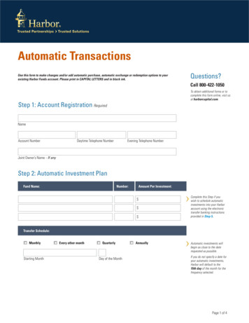
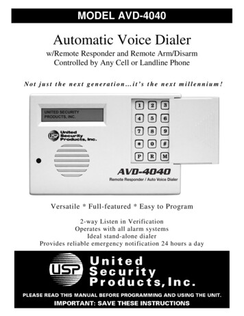
If a layout has multiple zones, it is called tandem guide-path. Only one vehicle serves each zone,so vehicle blocking and interference problems are totally eliminated. This layout configuration providesmultiple transportation possibilities, and if the cargo needs to be moved from one loop to another toreach its destination, there are transfer areas where the loops interact between them.Figure 2.1: Tandem configuration [6]2.2Navigation SystemsSince the introduction of AGVs there have been two main classifications for the navigation system: closepath and open path [8]. The selection of the type of navigation system is made based on the application,area size, cost, among others.Close path. The path is indicated through physical guidelines such as points or lines buried or attached to the ground and the vehicle is able to follow it using a sensor pointing to the ground. There arefive types of this system, two use points and the other three continuous lines. The ones that utilize pointsare inertial guidance and magnetic grid; on the other hand, magnetic tape guidance, wire guidance andoptical guidance use lines. As the path is fixed to the ground, the modification of the layout is not veryfrequent, making the system not too flexible; however this type of path is cheap and easy to implement.Open path. This kind of system has not physical paths for the AGV, though the paths are virtuallypre-defined in the control unit. As this system has not physical paths, it is used to cover problems relatedto flexibility, due to that the vehicles which use this type of navigation system can change the path fastercomparing with close path. There are two types of open path navigation systems: laser triangulationand natural frequent guidance. In these systems the probable deviation and the location of the AGV arecontrolled by the supervisory unit. Moreover, in this steering system the accuracy and flexibility are high,but it is much more expensive if it is compared to the close path method.Next, each system mentioned above will be briefly explained:7
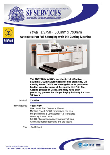
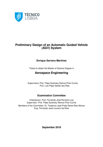
Laser triangulation. Nowadays this is the most popular method of AGV navigation [9]; consists inmounting reflective targets through the facility at known positions and a laser scanner on the vehicle.The laser scanner search for reflective targets and then with the vehicle control algorithms calculate theexact vehicle triangulation (see Figure 2.2).Figure 2.2: Laser triangulation [9]Inertial navigation. This system uses the feedback from 3 different devices to determine location.These devices are: a gyroscope on the vehicle which measures vehicle’s heading; a wheel encoder onthe vehicle that calculates the distance traveled; and some reference points, usually magnets, which areembedded in the floor at certain coordinates in a map of the system which are detected by a sensor onthe vehicle as it passes over the reference point (see Figure 2.3).Figure 2.3: Inertial guidance [9]8
Magnetic tape guidance. As its name suggest, a magnetic tape added to the floor is used and it isdetected by a sensor mounted on the vehicle (see Figure 2.4).Figure 2.4: Magnetic tape guidance [9]Magnetic grid guidance. This system is very similar to the inertial system, the main difference isthat in the inertial system a path was design with the reference points and now the reference pointsdesign a grid (see Figure 2.5). Nevertheless the performance is the same.Figure 2.5: Magnetic grid guidance [9]9
Natural feature navigation. The operating area is mapped and the reference images are stored inthe vehicle’s computer memory. The location of the vehicle is calculated based on its relative positioncompared to the natural features (see Figure 2.6).Figure 2.6: Natural feature guidance [9]Wire guidance. This system is similar to magnetic tape. It uses a continuous wire embedded in thefloor, and the antennas located in the vehicle detect the signal from it (see Figure 2.7).Figure 2.7: Wire guidance [9]10
Optical guidance. For this system a chemical or a tape strip fixed or painted on the floor it is used,and it is detected by a sensor mounted in the vehicle (see Figure 2.8). This method could be the simplestto introduce on a industry but it is not typically used because the floor line needs to be cleaned or thetape reapplied periodically.Figure 2.8: Optical guidance [9]2.3Vehicle typesVehicles are the central elements of an AGV system as they perform the transportation tasks, and canhave different characteristics depending on its application. The best way to categorize AGVs is by looking the loads they transport [5]. Next the main types of vehicles will be briefly explained.Forklift vehicles. This vehicle’s load unit are pallets or compatible containers, and it can be completely autonomous or it can have a seat to allow manual driving (illustrated in Figure 2.9 [10]). Theadvantage of a Forklift vehicle is that it is able to pick up or delivery load from the floor or variousheights, making it the AGV
AGV, Automated Guided Vehicle. This project aims to collect as much information as possible about AGV systems that currently exist and the subsequent preliminary design of an AGV system for a workshop of TAP Air Portugal Company. For this design, it was necessary to collect all possible information on this subject, to choose the best .