Transcription
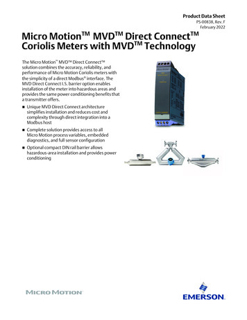
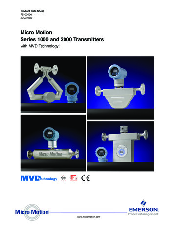
Product Data SheetPS-001885, Rev. FAugust 2016Micro Motion Model 5700 Transmitters withMVD TechnologyMicro Motion Model 5700 transmitters with MVD technology deliver powerful features that makemanaging your process easier.Repeatable, reliable, accurate measurements Faster processing speed delivers the best response even inthe most challenging applications such as meter proving,filling & dosing, and batching Smart Meter Verification provides you with the confidenceyou need in your meter performance Zero verification confirms the calibration and indicateswhen it’s time to re-zero the meter Approved for custody transfer and certified for SIL2 andSIL3, which provides measurement confidence andreliabilityA window into your process Easy access to detailed measurement history gives youvaluable insight into your process for bettertroubleshooting and optimization Real-time indication of multi-phase flow events allow forgreater process control High-accuracy density measurement reduces oreliminates waste in your process while the embeddedhistorian records upsets and process deviations.Productivity through simplified solutions Designed to minimize the time and expertise needed to install and operate the flowmeter Up to five fully configurable I/O channels that can be easily upgraded with changing needs Ethernet version includes multiple protocols on dual channels, plus a configurable I/O channel FOUNDATIONTM Fieldbus version includes IEC-61158-2 FOUNDATION Fieldbus output, a fixed mAoutput channel, and a configurable frequency / discrete output channel. Offline configuration and auditing through new file shuttling capability 6 6 &RPSDFW LQWHJUDO ZLUH WUDQVPLWWHU&RPSDFW LQWHJUDO WUDQVPLWWHU9HUVDWLOH ILHOG PRXQW WUDQVPLWWHU&RPSDFW FRQWURO URRP WUDQVPLWWHU)UHTXHQF\ LQSXW GLVFUHWH FRQWUROOHU,QWHJUDWHG FRQWURO DQG PHDVXUHPHQW SODWIRUP GYDQFHG ILHOG PRXQW WUDQVPLWWHU
Model 5700 TransmittersAugust 2016Micro Motion Model 5700 transmittersModel 5700 transmitters deliver the best measurement technology and offer unparalleled support – ensuring total measurementconfidence, valuable process insight and greater operational efficiency. These transmitters provide the scalability, compatibilityand performance that your application demands.Simplified installationand commissioningAn intuitive interface, spacious sideaccess wiring compartment andconvenient mounting brackets.Smart Meter Verification: advanced diagnostics foryour entire systemOur online tool verifies your meterperforms as well as the day it wasinstalled, giving you assurance in lessthan 90 seconds.Measurement history for easier troubleshootingand optimizationDetailed history files deliver key timestamped information about yourprocess from configuration changes andalerts to process events and statistics.Unmatched system connectivity and services interfacesConfigurable I/O versionUp to five fully configurable I/O channelswith multiple mA, discrete andfrequency outputs, and several powerfulservice interfacesEthernet versionTwo Ethernet outputs with EtherNet/IP,Modbus TCP, or PROFINET, plus oneconfigurable output.mA, frequency,Discrete input IUHTXHQF\ discrete inputsVFUHWH LQSXWVFieldbus versionFieldbus output, mA output, and aconfigurable channel for frequency ordiscrete output.Upto 3 mA outputs8S WR P RXWSXWVUpto 3 frequency or8S WR SXOVH RXWSXWVdiscrete outputs0RGEXV 56 Modbus/RS-485 57 56 HART/RS-485, 57 %HOO HART/Bell202863 VHUYLFH SRUW USP(service port) 57 FRQQHFWLRQ HARTWHUPLQDOVconnectionterminals2 Ethernet portsFieldbus outputmA output1 configurable I/Ochannel for mA,frequency, ordiscrete outputconfigurable channelfor frequency ordiscrete outputContentsModel 5700 enhancements .3Applications .4Electrical connections .5Input/output signal detail .6Digital communications .13Power supply .152Environmental limits . 15Environmental effects . 16Hazardous area classifications . 16Physical specifications . 20Dimensions . 22Ordering information . 23www.micromotion.com
Model 5700 TransmittersAugust 2016Model 5700 enhancementsInternal memoryPhysical designThe Model 5700 transmitter provides a backup of: Transmitter configurationsMeter verification baseline and historyData logLicensing key Conduit and terminal compartments are accessible from thesidesModular board stack designSpacious wiring compartmentsRemote mounting bracketA Universal Service Port (USP) connects and transfers datausing standard, easily available equipmentIf you need to replace your transmitter, move your old memoryto the new transmitter without losing any data or licensinginformation.Troubleshooting toolsSoftware licensingThe Model 5700 transmitter stores data in non volatile memorywith Real Time Clock, including:Software licensing makes it possible to: Purchase permanent features and add them laterTrial features, such as concentration measurement, for 60days before buyingOrder up to 5 input/output channels through the licenseLarge graphical display Supports multiple languagesSupports full configuration capabilities directly from thedisplayProvides understandable alert codes Meter fingerprintAudit trailAlert logLong term data historian: 5-minute Min, Max, Avg, Std Dev(10 years)Short term data historian: 1-second data (30 days)The Model 5700 transmitter contains descriptive alertsdescribing the issue and recommended steps for resolution. Follows NE 107 StandardTwo-phase flow detectionTwo-phase flow detection provides clear, concise informationabout fluid conditions, including notification about thefollowing three fluid regimes: Single phaseModerate two-phase flowSevere two-phase flowwww.micromotion.com3
Model 5700 TransmittersAugust 2016ApplicationsApplications are custom designed programs and software that offer additional functionality and performance to transmitters. Theseapplications are available through options in the transmitter model code, see the ordering information section for details.Smart Meter VerificationAdvanced Phase MeasurementProvides a quick, complete assessment of a Micro MotionCoriolis meter, determining whether the meter has beenaffected by erosion, corrosion, or other influences affectingmeter calibration. No secondary references are required toperform this operation, and the meter can continue normalprocess measurement while the test is in progress. Discrete batch control Simple batch control based on totalizer valuesFor transmitters with analog or intrinsically safe outputs, thefrequency output can be configured as a discrete outputAutomatic overshoot compensationNote:Discrete batch control is not available with 5700 FOUNDATIONFieldbus models Accurately measures liquid or gas flow in limited multiplephase conditions- Immediate and continuous access to production orprocess data- Real time reporting of Gas Void Fraction (GVF)Facilitates reliable measurement at a fraction of the cost oftrue multi-phase meters- Historian automatically captures all production data- Little to no maintenance or calibrationCombine with Net Oil Computer (NOC) or ConcentrationMeasurement to measure two liquids in the presence of gas- Provides single well real-time Net Oil and Net Watermeasurements- Improves Concentration Measurement in processes withintermittent entrained gasPetroleum measurement and APIcorrection optionAdds the following features: Accepts inputs from temperature and pressure devicesCalculates values as per May, 2004 API Chapter 11.1- Relative density (specific gravity and API gravity) atreference temperature from observed density andtemperature- Volume corrected to reference temperature and pressureCalculates flow-weighted average temperature and flowweighted average observed density (specific gravity and APIgravity)Concentration measurementProvides concentration measurement based on either industryspecific or liquid-specific units and relationships. Standardmeasurement options include: Industry-specific:- Brix- Plato- Balling- Baumé at SG60/60- Specific gravityLiquid-specific:- %HFCS- Concentration derived from reference density- Concentration derived from specific gravityAdditionally, the application can be customized for site-specificconcentration measurement (such as %HNO3, %NaOH).4www.micromotion.com
Model 5700 TransmittersAugust 2016Electrical connectionsConfigurable I/O versionConnectionDescriptionInput/OutputUp to 5 pairs of wiring terminals for transmitter I/O and communicationsPower Sensor One pair of wiring terminals accepts AC or DC powerOne internal ground lug for power-supply ground wiring4-wire remote mount – 4 terminals for connection to 4-wire sensor9-wire remote mount – 9 terminals for connection to 9-wire sensorService port (HART)Two clips for temporary connection to the service portUniversal Service PortA USP (Universal Service Port) connected to commercially-available USB equipment and cablesEthernet versionConnectionDescriptionEthernet PortsTwo Ethernet ports for EtherNet/IP, Modbus TCP, PROFINET, and web server connectionsInput/OutputOne configurable channel for mA output, frequency output, discrete output, or discrete inputPower Sensor One pair of wiring terminals accepts AC or DC powerOne internal ground lug for power-supply ground wiring4-wire remote mount – 4 terminals for connection to 4-wire sensor9-wire remote mount – 9 terminals for connection to 9-wire sensorUniversal Service PortA USP (Universal Service Port) connected to commercially-available USB equipment and cablesEmbedded web serverConnect to embedded web server via Ethernet connection for on-board configuration or data transferFOUNDATION Fieldbus versionConnectionDescriptionInput/OutputFOUNDATION Fieldbus output, One fixed channel for mA output. One configurable channel forfrequency output or discrete output. These outputs are available as intrinsically safe, or non-intrinsicallysafe, based on the output option selected.Power Sensor Universal Service PortOne pair of wiring terminals accepts AC or DC powerOne internal ground lug for power-supply ground wiring4-wire remote mount – 4 terminals for connection to 4-wire sensor9-wire remote mount – 9 terminals for connection to 9-wire sensorA USP (Universal Service Port) connected to commercially-available USB equipment and cablesNotes: Each screw terminal connection accepts one or two solid conductors, 24 to 12 AWG (0.20 to 3.3 mm2) or one or two strandedconductors, 22 to 14 AWG (0.38 to 2.3 mm2). Each plug type connector accepts one stranded or solid conductor, 24 to 12AWG (0.20 to 3.3 mm2). For integral mount transmitters (mounting code I), the connection between the transmitter and the sensor is not normallyaccessed.www.micromotion.com5
Model 5700 TransmittersAugust 2016Input/output signal detailAvailable channelsOutput optionSignalConfigurable I/O(output boardcode “A”)Wiring terminals 1Channel optionsChannel A2Channel B3mA output 1(HART)4Channel C56Channel D78mA output 2mA output 3mA inputFrequencyoutput 2 (1)Frequencyoutput 1Frequencyoutput 2(1)Discrete output 1 Discrete output 2Discrete input 1Channel E910RS-485Discrete output 3Discrete input 2Frequency inputEthernet (output Channel optionsboard code “C”)(2)(2)EtherNet/IPEtherNet/IPModbus TCP(2)Modbus TCP(2)(2)PROFINETPROFINET(2)mA outputFrequency outputDiscrete outputDiscrete inputOutput optionSignalWiring terminals 1FOUNDATIONfieldbus (outputboard code “E”)intrinsically safeH1 OutputsFOUNDATIONfieldbus (outputboard code “N”)H1 outputsChannel A2Channel B3Channel Options FOUNDATIONFieldbus(FISCO “ia” orFISCO “ic”)OffChannel Options FOUNDATIONFieldbusOff45IS mA Output6Channel C78IS Frequencyoutput910OffIS DiscreteoutputmA OutputFrequencyoutputOffDiscrete output(1) Frequency output 2 can be mapped to Channel B or D. For multiple frequency outputs, use Frequency 1 on Channel C and Frequency 2 on either Channel B or D.(2)The same protocol must be ordered on both Channel A and B. ProLink and the Integrated Webserver can always be connected to either Channel A or B.6www.micromotion.com
Model 5700 TransmittersAugust 2016Channel A specificationsOutput optionSpecificationmA outputmA output max loopresistanceConfigurable I/O(output board code“A”)Internal voltage24VDC (nom)820 ohmExternal voltage30VDC (max)1080 ohm @ 30VDCScalable range4-20mADownscale faultConfigurable from 1.0 – 3.6 mA,default value 2.0 mAUpscale faultConfigurable from 21.0 – 23.0 mA,default value 22.0 mALinearity0.015 %SpanSpan 16mAEthernet (outputboard code “C”)10BASE-TFOUNDATIONFieldbus (outputboard code “E”)FOUNDATION Fieldbus H1 output100BASE-TXWiring is intrinsically safe withintrinsically safe power supplyTransmitter fieldbus circuit is passive,and draws power from the fieldbussegment. Current draw is 13 mA.Manchester encoded digital signalconforms to IEC 61158-2FOUNDATIONFieldbus (outputboard code “N”)FOUNDATION Fieldbus H1 outputFOUNDATION fieldbus wiring is nonincendiveTransmitter fieldbus circuit is passive,and draws power from the fieldbussegment. Current draw is 13 mA.Manchester encoded digital signalconforms to IEC 61158-2Note:mA output is linear with process from 3.8 to 20.5 mA, per NAMUR NE-43 (February 2003).www.micromotion.com7
Model 5700 TransmittersAugust 2016Channel B specificationsOutput optionSpecificationConfigurable I/O Internal voltage(output boardcode “A”)External voltagemA outputmA output maxloop resistanceFrequencyoutput (2)Discrete output (1)24VDC (nom)820 ohm24VDC (nom)24VDC (nom)22mA sourcing7mA sourcing30VDC (max)30VDC (max)500mA (max)sinking500mA (max)sinking30VDC (max)1080 ohm @ 30VDCScalable range4-20mA0.01 Hz – 10 kHzDownscale faultConfigurable from1.0 – 3.6 mA, defaultvalue 2.0 mA0HzUpscale faultConfigurable from21.0 – 23.0 mA,default value 22.0mAConfigurable from10 Hz to 14.5 kHz,default value 14.5 kHzLinearity0.015 %SpanSpan 16mAResolution.4 uA /- 1 pulseEthernet (output 10BASE-Tboard code “C”)100BASE-TXFOUNDATIONfieldbus (outputboard code “E”)FOUNDATIONfieldbus (outputboard code “N”)8External voltage30VDC (max)869 ohms @ 30VN/AN/A10VDC (min)Scalable range4-20mADownscale faultConfigurable from1.0 – 3.6 mA, defaultvalue 2.0 mAUpscale faultConfigurable from21.0 – 23.0 mA,default value 22.0mALinearity0.015 %SpanSpan 16mAEntity parametersUi 30V, Ii 484mA,Pi 2.05W,Ci 0.27nF, Li 5uHExternal voltage30VDC (max)869 ohms @ 30V10VDC (min)Scalable range4-20mADownscale faultConfigurable from1.0 – 3.6 mA, defaultvalue 2.0 mAUpscale faultConfigurable from21.0 – 23.0 mA,default value 22.0mALinearity0.015 %SpanSpan 16mAwww.micromotion.com
August 2016Model 5700 TransmittersNotes: mA output is linear with process from 3.8 to 20.5 mA, per NAMUR NE-43 (February 2003). Fieldbus Channel B graph and equationsA. Loop resistor (ohms)B. Supply voltage VDC (volts)C. Rmax max value of loop resistor allowedD. Rmin min value of loop resistance requiredLoop Resistance EquationRmax (Vsupply - 10V)/0.023Rmin 0 Ω , Vsupply 25VRmin 200 Ω, Vsupply 25Vwww.micromotion.com9
Model 5700 TransmittersAugust 2016Channel C specificationsOutput optionSpecificationmA outputConfigurable I/O(output boardcode “A”)Internal voltage 24VDC (nom)andExternal voltage 30VDC (max)Ethernet (outputboard code “C”)Scalable range4-20mAFrequencyoutput (1)Discreteoutput (2)Discreteinput (1)820 ohm24VDC (nom)24VDC (nom)24VDC (nom)22mA sourcing7mA sourcing7mA sourcing30VDC (max)30VDC (max)30VDC (max)500mA (max)sinking500mA (max)sinking1080 ohm @30VDC0.01 Hz – 10 kHzDownscale fault Configurable from1.0 – 3.6 mA,default value 2.0mA0HzUpscale faultConfigurable from10 Hz to 14.5 kHz,default value 14.5 kHzConfigurable from21.0 – 23.0 mA,default value 22.0mAAccuracyLinearity10mA outputmax loopresistance /- 1 pulse0.015 %SpanSpan eshold0.6VDCwww.micromotion.com
Model 5700 TransmittersAugust 2016Output optionSpecificationFOUNDATIONfieldbus (outputcode “E” )External voltageFOUNDATIONfieldbus (outputcode “N” )mA outputmA outputmax loopresistanceFrequencyoutput (1)Discreteoutput (2)30 VDC (max)30 VDC (max)(1)8 VDC (min) (2)8 VDC(min)Scalable range0.01 Hz - 10 kHzDownscale fault0HzUpscale faultConfigurable from10 Hz to 14.5 kHz,default value 14.5 kHzResolution /- 1 pulseEntityparametersUi 30V, Ii 484mA,Pi 2.05W,Ci 11.27nF, Li 5uHExternal voltage30 VDC (max)8 VDC(min)(3)Scalable range0.01 Hz - 10 kHzDownscale fault0HzUpscale faultConfigurable from10 Hz to 14.5 kHz,default value 14.5 kHzResolution /- 1 pulseDiscreteinput (1)30VDC (max)8 VDC (min) (4)(1) Load resistor (500 Ω resistance recommended for 24V supply.) Use the following equations for other load resistance values:Rmax [(Vsupply - 6V) / 0.003] - Rbarrier (maximum value of load resistor allowed)Rmin 0 ohms(2) Current (Vsupply - 0.8V) / (1690 ohms barrier internal resistance in ohms load resistor in ohms)(3) Load resistor (500 Ω resistance recommended for 24V supply.) Use the following equations for other load resistance values:Rmax [(Vsupply - 6V) / 0.003] (maximum value of load resistor allowed)Rmin 250 ohms (minimum value of load resistance required)(4) Current (Vsupply - 0.8V) / (1690 ohms load resistor in ohms)Note:mA output is linear with process from 3.8 to 20.5 mA, per NAMUR NE-43 (February 2003).www.micromotion.com11
Model 5700 TransmittersAugust 2016Channel D specificationsOutput OptionSpecificationFrequency output (2) mA inputDiscreteoutput (3)Discreteinput (2)FrequencyinputConfigurable I/O(output boardcode “A”)Internalvoltage24VDC (nom)24VDC (nom)24VDC (nom)24VDC (nom)Externalvoltage30VDC (max)24VDC (nom)2.21 kilo ohm pull-upresistor2.21kilo ohm pull- 2.21 kilo ohmup resistorpull-up resistor2.21 kilo ohmpull-upresistor30VDC (max)30VDC (max)30VDC (max)Maxfrequency100 Hz3500 hreshold0.6VDC0.6VDC30VDC (max)500mA (max) sinkingScalable range 0.01 Hz – 10 kHz500mA (max)sinking4 - 20 mAFaultindication ifmA inputdrops below3.8 mA or goesabove 20.5 mADownscalefault0HzUpscale faultConfigurable from 10Hz to 14.5 kHz,default value 14.5kHzAccuracy /- 1 pulseInputresistanceEthernetN/AFOUNDATIONfieldbus (outputcode “E” or “N”)N/A100 ohmChannel E specificationsOutput optionSpecificationConfigurable I/O (output board code “A”)RS-485 ModbusEthernet (output board code “C”)N/AFOUNDATION Fieldbus (output board code “E” or “N”)N/ASensor input mounting codesMounting codesDescriptionI (integral mount)Integrally mounted to sensor, no external input connectionC (9-wire remote mount)One 9-wire sensor signal input connection, intrinsically safeR (4-wire remote mount)One 4-wire sensor signal input connection, intrinsically safe12www.micromotion.com
Model 5700 TransmittersAugust 2016Digital communicationsProtocolsOutputs and descriptionsModbus/USP Modbus/RS-485,HART/RS-485 HART/Bell 202 FOUNDATION fieldbus EtherNet/IP/Ethernet Modbus TCP/Ethernet PROFINET/Ethernet www.micromotion.comOne service port that can be used for a temporary connection onlyConnects to a PC via USB as if the transmitter had a built-in USB/RS-485 converterSupports all Modbus data ratesRequires a USB A/male-to-A/male cableAvailable on Channel E, if purchasedOne RS-485 output can be used for direct connection to HART or Modbus host systemsAccepts data rates between 1200 baud and 38.4 kilobaud115.2 kilobaud is also available as a special order itemUses the latest HART 7 standardAvailable on Channel A, if purchasedHART Bell 202 signal is superimposed on the primary milliamp output, and is available for hostsystem interfaceRequires 250 to 600 ohms load resistanceUses the latest HART 7 standardAvailable on Channel A.Models/output codes:- Model 5700 with output code “E” is FISCO “ia”certified in Zone 1 / Div 1and is FISCO “ic”certified in Zzone 2 / Div 2 (formerly known as FNICO).- Model 5700 with output code “N”.Transmitters are registered with the Fieldbus Foundation, and conform to the FOUNDATIONfieldbus H1 protocol specification.FISCO:- Field device in compliance with EN 60079-11:2012 and IEC 60076-11:2011- Ui 33 V, Ii 380 mA, Pi 5.32 W, Ci 0.27 nF, Li 5 μHAvailable on Channel A and Channel BSupports Auto Negotiate with date rates of 10 MB and 100 MB and half and full duplexSupports Auto Detect of Ethernet Crossover cablesSupports Dynamic Host Configuration Protocol (DHCP)Supports Device Level Ring (DLR)Supports Address Conflict Detection (ACD)Supports Quality of Service (QoS)Supports file object for EDS downloadConforms to ODVA EtherNet/IP Specification CT 12Conforms to the 10BASE-T and 100BASE-TX Ethernet standardsAvailable on Channel A and Channel BSupports Auto Negotiate with data rates of 10 MB and 100 MB and half and full duplexSupports Auto Detect of Ethernet Crossover cablesSupports Dynamic Host Configuration Protocol (DHCP)Uses v1.1b of the Modbus TCP standardConforms to the 10BASE-T and 100BASE-TX Ethernet standardsAvailable on Channel A and Channel BSupports Auto Negotiate with data rates of 10 MB and 100 MB and half and full duplexSupports Auto Detect of Ethernet Crossover cablesConforms to Conformance Class A v2.31 standardConforms to the 10BASE-T and 100BASE-TX Ethernet standards13
Model 5700 TransmittersAugust 2016Model 5700 with FOUNDATION fieldbus supportFieldbus software functionalityDiscrete input function blockModel 5700 FOUNDATION fieldbus software is designed to permitremote testing and configuration of the transmitter using theDeltaV Fieldbus Configuration Tool, or other FOUNDATIONfieldbus compliant hosts. The Coriolis sensor signal ischannelled through the flowmeter to the control room and theFOUNDATION fieldbus configuration device.One permanent Discrete Input (DI) function block can beassigned to any of the discrete input variable channels in thetransducer block. The DI block channels are: forward/reverseindication, zero in progress, fault condition indication, andmeter verification failure.Transducer blocksOne permanent Discrete Output (DO) function block can beassigned to any of the discrete output variable channels in thetransducer block. The DO block channels are: Start Sensor Zero,Increment CM Curve, Start Meter Verification in ContinuousMeasurement Mode, Reset All Process Totals, Start/Stop AllTotals, Reset Config Totals 1-7.Transducer blocks hold data from the Coriolis sensor, includingprocess variables, configuration, calibration, and diagnostics.The Model 5700 transmitter with FOUNDATION fieldbus providesup to seven transducer blocks: Measurement - For process and diagnostic variables andconfiguration of process parameters.Device - For device, display, channels configuration anddevice alert informationTotal inventory - For configuration of device totals andinventoriesMeter Verification - For Smart Meter VerificationAPI referral - For petroleum measurement calculations usingAPI MPMS Chapter 11.1Concentration Measurement- For complex density and concentration calculations(e.g.,%HFCS, SG60/60)APM - For Advance Phase Measurement and NOCcalculationsResource blockThe resource block contains physical device information,including available memory, manufacturer identification, typeof device, and features.Analog input function blocksThe Analog Input (AI) function block processes themeasurement from the Coriolis sensor and makes it available toother function blocks. It also allows filtering, alarm handling,and engineering unit changes. Each of the four Model 5700 AIblocks can be assigned to one of 27 available variables. Thereare four permanent Analog Input function blocks.Discrete output function blockProportional integral derivative function blockOne permanent Proportional Integral Derivative (PID) functionblock combines all the necessary logic to performproportional/integral/derivative control. The block supportsmode control, signal scaling and limiting, feed forward control,override tracking, alarm limit detection, and signal statuspropagation.Integrator function blockTwo permanent Integrator (INT) function blocks providesfunctionality for the transmitter totalizers. Any of 7 internaltotals or any of 7 internal inventories can be selected and reset.Diagnostics and serviceModel 5700 transmitters automatically perform continuous selfdiagnostics. Using the Device transducer block, the user canperform on-line testing of the transmitter and sensor.Diagnostics are event driven and do not require polling foraccess.PlantWeb Field Diagnostic is supported. The diagnosticinformation is based on NAMUR NE 107 standard.Analog output function blocksThe AO function block assigns an output value to a field devicethrough a specified channel. The block supports mode control,signal status calculation, and simulation. The AO block canreport pressure from an external pressure source, temperaturefrom an external temperature source, or watercut from anexternal device. There are two permanent Analog Outputfunction blocks.14www.micromotion.com
Model 5700 TransmittersAugust 2016Power Supply Self switching AC/DC input, automatically recognizes supply voltage Complies with Low Voltage Directive 2006/95/EC per IEC 61010-1 Ed. 3.0 2010-06; Overvoltage Category II, Pollution Degree 2 For European installations, install a switch or circuit breaker that is suitably located and easily reached. Mark the switch or circuitbreaker as the disconnecting device for the transmitter, in compliance with the Low Voltage Directive 2006/95/EC.TypeValueAC power DC power Fuse85 to 265 VAC, 50/60 Hz6 watts typical, 11 watts maximum18 to 100 VDC6 watts typical, 11 watts maximumSize the length and diameter of power conductors to provide 18VDC minimum at the power terminals at aload current of 0.7A1.5A Slow Blow (UL 248-14)Environmental limitsAmbient temperature limitsTypeFahrenheitCelsius–40 to 149 F–40 to 65 COperatingNote:The display can lose visibility below –22 F (–30 C).Storage–40 to 185 F–40 to 85 CVibration limitsMount typeValueNon truck mountMeets IEC 60068-2-6, endurance sweep, 5 to 2000 Hz, 50 sweep cycles at 1.0 gTruck mountMeets IEC 60068-2-6, endurance sweep, 5 to 2000 Hz, 50 sweep cycles at 1.0 g (remotemount)Humidity limitsThe humidity limits are 5 to 95% relative humidity, non-condensing at 140 F (60 C).www.micromotion.com15
Model 5700 TransmittersAugust 2016Environmental effectsEMI effectsComplies with: EMC directive 2004/108/EC per EN 61326 Industrial; check availability for your country NAMUR NE-21 (09.05.2012)Ambient temperature effectAmbient temperature effect on mA outputs shall not exceed /-0.005% of span per degree C.Hazardous area classificationsCSA, and CSA-US Ambient temperature is limited to -40 F (-40 C) to 149 F (65 C) for CSA compliance. Class I, Div. 1, Groups C and D. Class II, Div. 1, Groups E, F, and G explosion proof (when installed with approved conduit seals).Otherwise, Class I, Div. 2, Groups A, B, C, and D. Provides nonincendive sensor outputs for use in Class I, Div. 2, Groups A, B, C, and D; or intrinsically safe sensor outputs for use inClass I, Div. 1, Groups C and D or Class II, Div. 1, Groups E, F, and G.CodeDescriptionAAClass I, Div. 1, Groups C and D. Class I, Div. 2, groups A,B,C,D Class II, Div. 1, Groups E, F, and G explosion proof (wheninstalled with approved conduit seals).2AClass I, Div. 2, Groups A, B, C, and D.IECExAmbient temperature range is -40 F (-40 C) to 149 F (65 C) for IECEx compliance.Output optionCodeApproval (See IECEx approval codes)Configurable I/OAIAEthernetEx db [ib] IIB H2 T6 GbStandard displayCEx db [ib] IIC T6 GbNo display or IIC displayFOUNDATIONFieldbusNEx tb [ib] IIIC T75 C Db IP66/IP67Dust markingFOUNDATIONFieldbusFISCO “ia”EEx db [ia Ga] [ib] IIB H2 T6 GbStandard displayEx db [ia Ga][ib] IIC T6 GbNo display or IIC displayEx tb [ia Da] [ib] IIIC T75 C DbIP66/IP67Dust markingEx db e [ib] IIB H2 T6 GbStandard displayEx db e [ib} IICT6 GbNo display or IIC displayConfigurable I/OAFOUNDATIONFieldbusNFOUNDATIONFieldbusFISCO “ia”E16EAFlameproofIncreased Safety (1)Ex tb [ib] IIIC T75 C Db IP66/IP67Dust markingEx db e [ia Ga][ib] IIB H2 T6 GbStandard displayEx db e [ia Ga] [ib] IICT6 GbNo display or IIC displayEx tb [ia Da] [ib] IIIC T75 C DbIP66/IP67Dust markingwww.micromotion.com
Model 5700 TransmittersAugust 2016Output optionCodeApproval (See IECEx approval codes)Configurable I/OA3A(Integralon sNon sparking(1)CNEFISCO “ic”formerly knownas FNICOConfigurable CO “ic”formerly knownas FNICOACNon sparking (1)3A(remotefromsensor)NEEx nA nC IIB H2 T5GcStandard displayEx nA nC IIC T5 GcNo display or IIC displayEx tc IIIC T75 C Dc IP66/IP67Dust markingEx nA nC IIB H2 T4 GcStandard displayEx nA nC IIC T4 GcNo display or IIC displayEx tc IIIC T75 C Dc IP66/IP67Dust markingEx nA IIB H2 T4 GcStandard displayEx nA IIC T4 GcNo display or IIC displayEx tc IIIC T75 C Dc IP66/IP67Dust markingEx nA [ic] IIB H2 T4 GcStandard displayEx nA [ic] IIC T4 GcNo display or IIC displayEx tc IIIC T75 C Dc IP66/IP67Dust markingEx nA nC [ib Gb] IIB H2 T5 GcStandard DisplayEx nA nC [ib Gb] IIC T5 GcNo display or IIC displayEx tc [ib Db] IIIC T75 C Dc IP66/IP67Dust markingEx nA nC [ib Gb] IIB H2 T4 GcStandard DisplayEx nA nC [ibGb] IIC T4 GcNo display or IIC displayEx tc [ib Db] IIIC T75 C Dc IP66/IP67Dust markingEx nA [ib Gb] IIB H2 T4 GcStandard Disp
Micro Motion Model 5700 Transmitters with MVD Technology Micro Motion Model 5700 transmitters with MVD technology deliver powerful features that make managing your process easier. Repeatable, reliable, accurate measurements Faster processing speed delivers the best response even in the most challenging applications such as meter proving,