Transcription
P17105: HABIP-DAQCAuthor: Sydney KaminskiMaxon Motor & Motor Controller ManualNote: This manual is only for use for the Maxon motor and controller outlined below. Thisinformation is based upon the tutorial videos found online and through testing.NOTE: Maximum Permitted Supply Voltage: 10 – 70 VDC. Do not exceed 76 VDC or wrongpolarity, or it will destroy the unit. Minimum output voltage is 8 VDC. Continuous Max OutputCurrent: 10 A / short-time (acceleration, 20 seconds) max. 30 A.Necessary Equipment: Motor (EC 90 flat Ø90 mm, brushless, 90 Watt, with Hall sensors, PN # 323772) Motor Controller (ESCON 70/10, 4-Q Servocontroller for DC/EC Motors, 10/30 A, 10 –70 VDC, PN # 422969) Maxon Motor Controller Software (ESCON Setup – Studio 2.2/Firmware 0150h) Suitable Cables for Power (J1) : 0.2 – 2.5 mm 2 multi-core & single wire, AWG 24-12 Suitable Cables for Motor (J2) : 0.2 – 2.5 mm 2 multi-core & single wire, AWG 24-12 Suitable Cables for Hall Sensors (J3) : 0.14 – 1.5 mm 2 multi-core & single wire, AWG28-14 J4 will not be used. The HABIP motor does not have an encoder. Suitable Cables for Digital I/Os (J5) : 0.14 – 1.5 mm 2 multi-core & single wire, AWG28-14 Suitable Cables for Analog I/Os (J6) : 0.14 – 1.5 mm 2 multi-core & single wire, AWG28-14Software Set-Up (For Testing with Arduino Uno): Connect the servocontroller to the computer that will be running the motor software viaUSB. Open ESCON Studio 2.2. The Startup Wizard should begin automatically.o If this does not start automatically, go to the “Tools” dropdown menu and select“Setup Wizard.”o Read the safety instructions and select “Yes, I have read the above instructions.”Click “Next.”o A description of the device connected is shown. Double-check to ensure that it isthe correct motor controller. Click “Next.”o Select “Maxon EC Motor.” Click “Next.”o Enter the motor data that is needed. For the motor being used on the HABIP, the constants that need to beinputted are as follows:2/14/20171
P17105: HABIP-DAQCooooo2/14/2017Author: Sydney Kaminski Speed Constant: 135 RPM/V Thermal Time Constant Winding: 34.1 s Number of Pole Pairs: 12 Click “Next.”Enter the system data that is needed. Note: This is not necessarily just based upon the motor. Ensure that thevalues inputted here are the maximums for the entire system so as toensure that the system is not harmed. The values for the HABIP systems that are to be inputted are as follows: Max Permissible Speed: 5000 RPM (3190 RPM No Load Speed) 2590 RPM Nominal Current: 6.0000 A Max Output Current Limit: 30.0000 A Click “Next.”The next page is entitled “Detection of Rotor Position.” Under the “Select Type of Sensor” drop-down menu, click “Digital HallSensors.” Select “maxon” for “Hall Sensor Polarity.” Click “Next.”Select the type of sensor being used for measuring the speed. For the motor being utilized by the HABIP teams, select “Available HallSensors,” as there is no encoder. Click “Next.”Select the desired mode of operation. There are three modes: Current Controller Speed Controller (Closed Loop) Speed Controller (Open Loop) Select “Speed Controller (Closed Loop)” for the HABIP motor. Click “Next.”This next page is the “Enable” page. This page is used to determine the inputnecessary to start up the motor. There are several “Enable” functionalities: Enable Enable & Direction Enable CW Enable CCW Enable CW & CCW2
P17105: HABIP-DAQCAuthor: Sydney Kaminski oooo2/14/2017There is a section to assign this functionality: Select a digital input (1, 2, 3 or 4) to assign the “Enable”functionality to it.o For the HABIP motor, assign it to “Digital Input 2.” The polarity must also be specified as either “High Active” or“Low Active.”o For the HABIP motor, specify the polarity as “HighActive.” Click “Next.”This page will define the input functionality. There are several options for inputs: Analog Set Value PWM Set Value 2 Fixed Set Value Fixed Set Value For the HABIP motor, assign the input as PWM Set Value Speed at: 10% : -5000.0 RPM Speed at 90% : 5000.0 RPM Click “Next.”This next page is to set the current limit on the motor. There are several types of current limit functionality: Analog Current Limit PWM Current Limit 2 Fixed Current Limit Fixed Current Limit Specify the maximum value for current. For HABIP, select “Fixed Current Limit.” Write down “30.0000 A.” Click “Next.”The speed ramp page allows for several possibilities for the motor: Analog Ramp Fixed Ramp No Ramp Active Select “Fixed Ramp” and write 1000 RPM/s for both theacceleration and deceleration of the HABIP motor. Click “Next.”The minimal speed page is used to allow for a low speed to be the Write “0.0 RPM” for the “Minimal Speed.”3
P17105: HABIP-DAQCAuthor: Sydney Kaminskio For the offset page, there are multiple options: Analog Offset PWM Offset RC Servo Offset Fixed Offset Select “Fixed Offset” and set to 0.0 RPM. Click “Next.”o This next page will set up the digital inputs and outputs of the motor controllersystem. Note: One of the digital inputs will be marked as “Enable” if it has beenselected earlier as one. Digital Input 1:o Noneo Stop Digital Input 2:o Noneo Stop Digital I/O 3:o Stopo Readyo Speed Comparatoro Current Comparator Digital I/O 4:o Stopo Readyo Speed Comparatoro Current Comparator Set up the motor controller as follows for the HABIP motor: Digital Input 1: PWM - Set Value Digital Input 2: Enable Digital I/O 3: None Digital I/O 4: None Note: Be sure to double-check that the inputs are within the constraints setby Maxon. The digital inputs and digital inputs/outputs have differentrequirements. Click “Next.”o The analog inputs will be selected at this page: Analog Input 1: Actual Speed2/14/20174
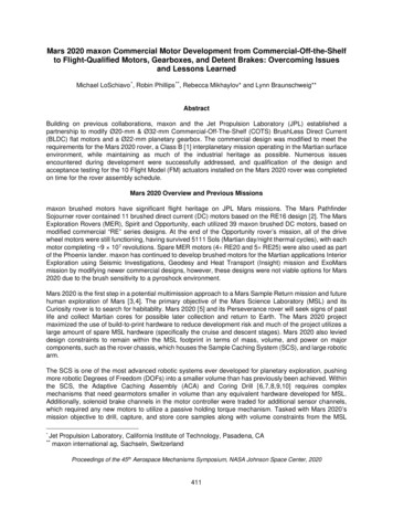
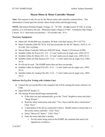
P17105: HABIP-DAQCAuthor: Sydney Kaminski Analog Input 2: Actual Current Averaged Click “Next.”o There are three analog outputs available from the controller. They have multiple options for functionality: None Fixed Value Actual Current Actual Current Averaged Actual Speed Actual Speed Averaged Demand Current Demand Speed Temperature Power Stage Click “Next.”o This next page will be used to specify any analog outputs that were chosen in theprevious step. Speed at: 0.000 V : -5000.0 RPM Speed at 3.000 V : 5000 RPM Click “Next.” Current at 0.000 V : 0.0000 A Current at 3.000 V : 10.0000 Ao This next page shows the configuration summary. Click “Show Wiring Overview.” This will show the wiring overview for the module based upon theconfiguration determined by the options chosen above.2/14/20175
P17105: HABIP-DAQCAuthor: Sydney KaminskiWiring Diagram2/14/20176
P17105: HABIP-DAQC2/14/2017Author: Sydney Kaminski7
P17105: HABIP-DAQC2/14/2017Author: Sydney Kaminski8
P17105: HABIP-DAQC2/14/2017Author: Sydney Kaminski9
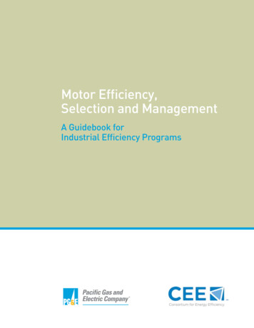
P17105: HABIP-DAQCAuthor: Sydney KaminskiFor Use With Arduino Uno For Testing Straight Motor Commands:NOTE: An Arduino Uno outputs an 8-bit PWM signal. The motor controller takes a 12-bitPWM signal.This section of the guide will be utilized to take tests without the use of a MSP430, and insteadwith an Arduino. This will be without a PID controller, so that data about a system might becollected and a plant model of the system be created. No IMU is attached in this setup.Example Sketch:2/14/201710
P17105: HABIP-DAQCAuthor: Sydney KaminskiThe above sketch shows the communication between the motor controller and the Arduino Uno.This sketch only send a PWM signal to motor and motor controller. This does not include any2/14/201711
P17105: HABIP-DAQCAuthor: Sydney Kaminskiform of PID controller or reaction wheel control. This sketch is used for testing the motor toensure good communication between the motor, motor controller, and Arduino. The settings inthe previous section must all be completed first, as they are saved to the motor controller. Setup the motor control software for data collection, as specified above. Upload the above sketch onto the Arduino Uno that is being used to control the motorcontroller. Hook up the Arduino, motor controller, motor, and switch as seen above in the pinoutdiagram.Regulation Tuning After setting up the motor and motor controller in the Startup Wizard, Regulation Tuningwill automatically pop up. Select “Auto-Tuning.” Section To Be Completed Soon. Click “Start.”2/14/201712
P17105: HABIP-DAQCAuthor: Sydney Kaminski Test results, similar to the ones seen above, should appear. Click “Finish.”2/14/201713
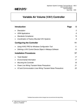
P17105: HABIP-DAQCAuthor: Sydney KaminskiSetting Up the Data Recorder Tool Upon opening the Data Recording Tool, click “Settings.” The above image will be seen. The four channels on the left hand side have many options for recording information forthe motor: Actual Speed Actual Speed Averaged PWM Input Hall Sensor Pattern Position Counter Hall Sensor Position Counter Encoder RC Servo Input Analog Input 1 Analog Input 2 Potentiometer 1 Potentiometer 2 Temperature Power Stage External Supply Voltage Current Analog Set Value Demand Current2/14/201714
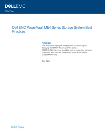
P17105: HABIP-DAQC Author: Sydney Kaminski Current Set Value Speed Analog Set Value Demand Speed Speed Ramp Value Offset Adjust Analog Set Value Offset Adjust Demand Value Analog Speed Ramp Actual Speed Ramp Acceleration Actual Speed Ramp Deceleration Analog Output 1 Analog Output 2 Power Index Motor Power Index AmplifierFor testing with the Arduino Uno, the options selected are: Actual Speed Actual Current PWM InputThe values below these options are to specify how the user wants to plot the data on theData Recording Tool.The Data Sampling area of the settings shows how long the user wants to run the test andhow many samples will be taken. The first two boxes are able to be edited. The last is automatically calculated. For this original test, approximately 1 minute of data is desired, so 60,000 ms wasinputted into the settings.Depending upon the set-up of the motor, the section below may be changed. If using a switch as outlined above, select “Single Trigger.” Select “Digital Signal.” Select “Enable” out of the several options. For mode, select “Disable Enable.” The time delay may then be decided below. This shows the amount of time it willtake until the Data Recording Tool will take record data.Click “OK.”The Data Recording Tool is now set up. In order to initiate the data recording, flip theswitch.To export the collected data, right click within the plot and click “Export RecordedData.”Example Data:2/14/201715
P17105: HABIP-DAQCAuthor: Sydney KaminskiFor Use With Arduino Uno For Testing with IMU (Without PID, to be Added Later)NOTE: The IMU outputs a 14-bit signal in regards to the gyroscope. The Arduino Uno2/14/201716
ensure good communication between the motor, motor controller, and Arduino. The settings in the previous section must all be completed first, as they are saved to the motor controller. Set up the motor control software for data collection, as specified above. Upload the above sketch onto the Arduino Uno that is being used to control the motor