Transcription
Leica ScanStationP40/P30System Field ManualVersion 4.0English
2ScanStation P40/P30, IntroductionIntroduction To use the product in a permitted manner, please refer to the detailed safety directions in the User Manual.PurchaseCongratulations on the purchase of a Leica ScanStation P40/P30 instrument.Product IdentificationThe type and serial number of your product are indicated on the type plate. Alwaysrefer to this information when you need to contact your agency or Leica Geosystemsauthorised service workshop.SymbolsThe symbols used in this manual have the following meanings:Type DescriptionImportant paragraphs which must be adhered to in practice asthey enable the product to be used in a technically correct andefficient manner.Trademarks Windows is a registered trademark of Microsoft CorporationAll other trademarks are the property of their respective owners.Validity of thismanualThis manual applies to the Leica ScanStation P40/P30 instruments.
Available documentationNameDescription/FormatLeica ScanStationProvides an overview of the product togetherP40/P30 Quick Guide with technical data and safety directions.Intended as a quick reference guide. Leica ScanStationAll instructions required in order to operate the P40/P30 User Manual product to a basic level are contained in theUser Manual. Provides an overview of theproduct together with technical data and safetydirections. Leica ScanStationDescribes the general operation of the product P40/P30 System Field in standard use. Intended as a quick referenceManualfield guide. Leica GeosystemsHDS Training ManualScanStation P40/P30, IntroductionTraining manual provided in the Leica HDStraining course by the local Leica HDS trainingand support team.3
ScanStation P40/P30, Introduction4Refer to the following resources for all Leica ScanStation P40/P30 documentation and software Leica ScanStation P40/P30 System USB Swing Card http://www.leica-geosystems.com/downloads ers-SW 5570.htm https://myworld.leica-geosystems.com
Table of ContentsIn this manualChapter1Description of the System1.123PagePacking / Unpacking1010Setting Up the Instrument122.12.22.32.412131518General InformationScanner Setup on TripodSetup Over a Benchmark with the Internal Laser PlummetInstrument HeightDescription of the User Interface203.13.23.33.4Front SideDisplayStatus BarOperating Principles202123314Switching the System On/Off345Remote Control366Main Menu40ScanStation P40/P30, Table of Contents5
ScanStation P40/P30, Table of Contents7Scanning7.17.27.3Scanning\Scan BeginScanning\Setup7.2.1Scanning\Setup\Quick Orientation7.2.2Scanning\Setup\Set Azimuth7.2.3Scanning\Setup\Known g\Setup\Auto Resection7.2.6Scanning\Setup\Setup Configuration7.2.7Scanning\Setup\Station ID Configuration7.2.8Scanning\Setup\Scale FactorScanning\Scan Parameters7.3.1Scanning\Scan Parameters\Field of View7.3.2Scanning\Scan Parameters\Resolution7.3.3Scanning\Scan Parameters\Image Control\Internal Camera7.3.4Scanning\Scan Parameters\Image Control\External Camera7.3.5Scanning\Scan Parameters\Filters7.3.6Scanning\Scan Parameters\Detail Scan7.3.7Scanning\Scan Parameters\.\Target 149152155
02122212278.48.58.68.78.88.9Traverse BeginTraverse ConfigurationTraverse Management8.3.1New Traverse8.3.2Edit Traverse8.3.3Delete Traverse8.3.4Traverse DataStarting a TraverseTraverse ForesightScanning and Imaging from a Traverse StationTraverse BacksightTraverse ResultsAdjustment ResultsScanStation P40/P30, Table of Contents7
ScanStation P40/P30, Table of ojects9.1.1Manage\Projects\New Project9.1.2Manage\Projects\Edit Project9.1.3Manage\Projects\Delete ts\Transfer ProjectManage\Targets9.2.1Manage\Targets\New Target9.2.2Manage\Targets\Edit Target9.2.3Manage\Targets\Delete TargetManage\Control Points9.3.1Manage\Control Points\New Project9.3.2Manage\Control Points\Edit Project9.3.3Manage\Control Points\Delete Project9.3.4Manage\Control Points\Import Control Points9.3.5Manage\Control Points\Data9.3.6Manage\Control Points\Data\New Control Point9.3.7Manage\Control Points\Data\Edit Control Point9.3.8Manage\Control Points\Data\Delete Control Point9.3.9Manage\Control Points\Data\Import Control Points9.3.10Manage\Control Points\Data\Delete All Control Points
10 Status10.110.210.310.4Status\Battery & MemoryStatus\System InformationStatus\Level & Laser PlummetStatus\WiFi11 Configuration11.111.211.311.4Configuration\Units & FormatsConfiguration\Date & TimeConfiguration\SettingsConfiguration\Language12 rTools\LicenseTools\Screen CalibrationCheck & AdjustScanStation P40/P30, Table of 3373399
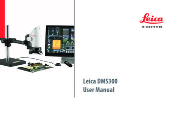
10ScanStation P40/P30, Description of the System1Description of the System1.1Packing / UnpackingUnpackingWhen in its transport container, the ScanStation P40/P30 can sit in either a face-upor face-down position.To take the instrument out of its container,grasp the handle and the base of the instrument, and lift.Use caution due to the weight of the instrument (12 kg).007860 001 Pack the instrument the same way it is delivered.
ScanStation P40/P30, Description of the System11
ScanStation P40/P30, Setting Up the Instrument122Setting Up the Instrument2.1General InformationUse the tripodThe instrument should always be set up on its tripod. Using the tripod specified forthe scanning system guarantees maximum stability during scanning operations. Always set up the instrument on its tripod. Do not set up the instrument directly onthe ground for scanning operations.It is always recommended to shield the instrument from direct sunlight and avoiduneven temperatures around the instrument.
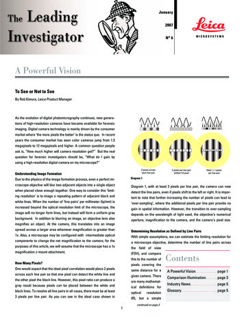
2.2Scanner Setup on TripodScanStationP40/P30 setupstep-by-step52662133144314007867 001 Shield the instrument from direct sunlight and avoid uneven temperaturesaround the instrument.1. Extend the tripod legs to allow for a comfortable working posture. Tighten thescrews at the bottom of the legs.2. Place the tribrach on the tripod and secure it with the central fixing screw.ScanStation P40/P30, Setting Up the Instrument13
ScanStation P40/P30, Setting Up the Instrument143. Set up the tripod so that the tripod plate is as horizontal as possible.4. Push the tripod legs firmly into the ground.5. Place the instrument on the tribrach and secure it with the locking knob of thetribrach.6. Level up the instrument using the instrument’s circular level. Turn two of the footscrews together in opposite directions. The index finger of your right hand indicates the direction in which the bubble should move. Now use the third footscrew to centre the bubble.
2.3Setup Over a Benchmark with the Internal Laser PlummetDescriptionThis topic describes an instrument setup over a marked ground point using the laserplummet. Geo-referencing of the Leica ScanStation P40/P30 is established by settingup over a known or assumed control point, with optional reference target measurement to set the azimuth direction, and establishing a local or global coordinatesystem.The Leica ScanStation P40/P30 allows you to traverse, resect or free-station. Knownazimuth or known backsight measurements can be observed. It is always possible to set up the instrument without the need for a marked groundpoint.With the dual-axis compensator enabled, the data scanned with ScanStation P40/P30is corrected automatically.About the plummet: The laser plummet described in this topic is built into the vertical axis of theinstrument. It projects a red spot onto the ground, making it much easier tocentre the instrument. The laser plummet cannot be used in conjunction with a tribrach equipped withan optical plummet.ScanStation P40/P30, Setting Up the Instrument15
16ScanStation P40/P30, Setting Up the InstrumentSetup with LaserPlummet step-bystepefgcdkhaajabjji007868 001 Shield the instrument from direct sunlight and avoid uneven temperaturesaround the instrument.1. Extend the tripod legs to allow for a comfortable working posture (a). Positionthe tripod approximately over the marked ground point, centring it as well aspossible (b).2. Place the tribrach on the tripod (c) and secure it with the central fixing screw (d).
3. Place the instrument on the tribrach (e) and secure it with the tribrach’s lockingknob.4. Turn on the instrument by pressing the ON/OFF button (f). Go to Status,Level & Laser Plummet, Plummet and activate the laser plummet (g).5. Move the tripod legs (a) and use the tribrach footscrews (h) to centre theplummet (i) over the ground point.6. Adjust the tripod legs (j) to level the circular level (k).7. By using the electronic level (Status, Level & Laser Plummet, Level) turn thetribrach footscrews (h) to precisely level the instrument.8. Centre the instrument precisely over the ground point (i) by shifting the tribrachon the tripod plate.9. Repeat steps 7. and 8. until the required accuracy is achieved.ScanStation P40/P30, Setting Up the Instrument17
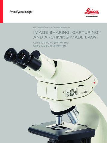
ScanStation P40/P30, Setting Up the Instrument182.4Instrument HeightScanStationP40/P30 heightsetup step-by-stepTo get an accurate height measurement use the GHM008 instrument height meter inconjunction with the GHT196 distance holder. Both are included with the scanner.1.627265007870 0011. Place tripod centrally over the groundpoint, level instrument.2. Click GHT196 distance holder to tribrach.It must "snap" onto the cover over anadjusting screw.3. Unfold measuring tongue, pull out tapemeasure a little.4. Insert GHM008 instrument height meterin the distance holder and attach.5. Swivel measure in the direction of theground point, pull out until the tip of themeasuring tongue touches the point onthe ground, keep under tension and donot allow to sag, clamp if necessary.6. Read height of the instrument (ground tilt axis) in the reading window at the redmarking (in the example 1.627 m).
For detailed information about the GHM008 instrument height meterand GHT196 distance holder refer to the GHM008/GHT196 user manualwhich is delivered with these items.The tilt axis height of the ScanStation P40/P30 is 250 mm. Take care touse the GHM008 which has a special scale to measure the height ofinstruments with a tilt axis height of 250 mm. Do not use a tape withany other scale.Alternatively the instrument height can be measured with a common,1:1 scaled measuring tape from the point on the ground to the littlenotch under the red Leica logo at both side covers of the scanner. Thisdistance will then be from the ground point to the tilt axis.ScanStation P40/P30, Setting Up the Instrument19
20ScanStation P40/P30, Description of the User Interface3Description of the User Interface3.1Front SideOverviewabcde004255 001a)b)c)d)e)ON/OFF buttonUSB socketLoudspeakerStylusTouch screen user interface
3.2DisplayOverviewfgabca) Timeh b) Captionc)d)e)f)g)i h)i)j j)de009203 002 enElementTitle barScreen areaMessage barStatus barEscape buttonMenu iconSHIFT buttonSoft keysDescriptionTimeThe current local time is shown.CaptionShows location in menu system.Title barShows name of current screen.ScanStation P40/P30, Description of the User Interface21
ScanStation P40/P30, Description of the User InterfaceElementDescriptionScreen areaWorking area of the screen.Message barShows messages.Status barShows current status information for the instrument.Escape buttonReturns to the previous screen.Menu iconSelecting menu icons opens submenus.SHIFT buttonDisplays the second level of soft keys.Soft keysCommands can be executed with the soft keys.22
3.3Status BarOverviewThe icons in the status bar display the current status information of the instrument.Clicking a status icon gives direct access to a detailed status description.abc def gh i jkl mn009204 002ScanStation P40/P30, Description of the User Interfacea)b)c)d)e)f)g)h)i)j)k)l)m)n)Range modeRange filterScale factorActive target typeDual-axis compensatorWiFi statusBluetooth statusInternal hard discExternal memoryStatus of external memoryExternal cameraExternal battery / AC power supplyInternal battery AInternal battery B23
ScanStation P40/P30, Description of the User Interface 24Internal battery A indicates the status of the battery in compartment A whichis located at the same side cover as the touch screen.Internal battery B indicates the status of the battery in compartment B at theopposite side cover without a screen.IconDescriptionRange modeRange mode enabledRange filterRange filter enabledScale factorScale factor enabled
IconDescriptionActive target typeLeica B/W 4.5" targetHDS black/white target 6"HDS black/white target 3"HDS sphere targetUser defined target of type Leica B/W 4.5"User defined target of type HDS black/white 6"User defined target of type HDS black/white 3"User defined target of type HDS sphereScanStation P40/P30, Description of the User Interface25
ScanStation P40/P30, Description of the User InterfaceIconDescriptionDual-axiscompensatorOn and levelledOffOn but out of rangeWiFiOnboard WiFi adapter on and connected.Onboard WiFi adapter off.Onboard WiFi adapter on.BluetoothOnboard Bluetooth adapter on and connected.Onboard Bluetooth adapter off.Onboard Bluetooth adapter on.External cameraExternal camera connected and selected for imageacquisition.26
IconDescriptionInternal hard discEmpty13% memory used25% memory used38% memory used50% memory used63% memory used75% memory used88% memory usedFullStatus of externalmemoryReady to be removedDo not removeScanStation P40/P30, Description of the User Interface27
ScanStation P40/P30, Description of the User InterfaceIconDescriptionExternal memoryEmpty17% memory used33% memory used50% memory used67% memory used83% memory usedFullExternal battery / ACpower supplyExternal battery connectedAC power supply connected28
IconInternal battery A/BDescriptionSymbols for the currently used battery:Empty20% capacity40% capacity60% capacity80% capacityFullScanStation P40/P30, Description of the User Interface29
ScanStation P40/P30, Description of the User InterfaceIconDescriptionSymbols for the currently unused battery:Empty20% capacity40% capacity60% capacity80% capacityFull30
3.4Operating PrinciplesKeyboards ontouchscreenThe system offers two different virtual keyboard layouts for user input: When an alphanumeric input field is selected with the stylus, the keyboard willappear in alphanumeric layout. This layout offers letters, numbers and specialcharacters.When an numeric input field is selected with the stylus, the keyboard willappear in numeric layout. This layout offers numbers and some special characters.ScanStation P40/P30, Description of the User Interface31
32ScanStation P40/P30, Description of the User InterfaceKeyboard layoutsAlphanumeric layout:afa)b)c)d)be)ced004942 002 enf)Input fieldAlphanumeric keypadBackspaceEnterToggle between letters andnumbers/special charactersShift - Toggle betweenlower case and upper casecharacters
Numeric layout:aebca)b)c)d)e)df004943 002 enScanStation P40/P30, Description of the User Interfacef)Input fieldBackspaceNumeric keypadEnterToggle between positiveand negative numberUnit calculator (optionalwhen distance units ft or fiare selected)33
ScanStation P40/P30, Switching the System On/Off4Switch onprocedure34Switching the System On/Off1. Set up the instrument as desired. Refer to chapter "2 Setting Up the Instrument"for more information.2. Press and hold the ON/OFF button for 2 seconds until a beep is audible.3. The instrument starts with several subsequent beeps and a short melody.4. The Leica Geosystems welcome screen starts.5. Wait until the Main Menu appears on the display.
Switch offproceduresShutdown via Main Menu:1. From the current menu return to the Main Menu.2. In the Main Menu press thebutton.3. In the popup window confirm the question Do you want to shutdown? withYes.4. Wait for the scanner to shut down.Shutdown via On/Off button:1. Press and hold the On/Off button for 1 second until a single beep is audible.2. Wait for the scanner to shut down.In case of a system crash (forced shutdown):1. Press and hold the On/Off button for 6 seconds until a double beep is audible.2. Wait for the scanner to shut down.ScanStation P40/P30, Switching the System On/Off35
ScanStation P40/P30, Remote Control365Remote ControlOverviewThe ScanStation P40/P30 can be controlled remotely by a Leica handheld controller(CS10, CS15, CS20 or CS35) or by external devices (Apple iOS or Android driven) viaWiFi communication.Installation of theScanStation PxxRemote ControlApp on the LeicaViva ControllerThe following hardware is needed: Viva Controller (CS10 or CS15) equipped with a WiFi adapter. Check the stickerThis device contains in the battery compartment of the Viva Controller: Incase a WLAN module is listed, the controller is equipped with a WiFi adapter.1. Copy the installation file Pxx RemoteControl.CAB onto a USB memory device.2. Switch on the Viva Controller and connect the USB memory device to thecontroller.3. In case SmartWorx Viva app is running, close this app by pressing Fn - Exit.4. Double-click My Device and navigate to the USB memory device.5. Double-click the file Pxx RemoteControl.CAB.6. Confirm the suggested installation folder Program Files by pressing OK withinthe Install Leica Geosystems AG Pxx dialog.7. The app will be installed. A start-up menu folder as well as a desktop icon will becreated.8. Disconnect the USB memory device.
Enable the WiFiadapter of yourViva Controller1. Go to Start - Settings - Control Panel.2. Double-click on Network and Dial-up Connections.3. Select the icon of the WiFi device (e. g. NXPWLAN1) and press File. If the menulists Disable, the WiFi device is already enabled. In this case leave the controlpanel without any changes. If the menu lists Enable, press Enable and leave thecontrol panel.4. Close the control panel.ScanStationP40/P30 RemoteControl1.2.3.4.5.6.7.8.Switch on the ScanStation P40/P30 and wait for the boot process to finish.Select Status to get to the Status Menu.In the Status Menu select Connections to open the WiFi menu.In the WiFi menu set: WiFi Operation Enabled WiFi Connection Ad-hoc modeStart the ScanStation Pxx Remote Control app on your Viva Controller by doubleclicking the desktop icon.Within the ScanStation Pxx Remote Control dialog press Find scanner and waitfor your ScanStation P40/P30 to be listed within the list of available scanners.As soon as your ScanStation P40/P30 is listed, select it and press Connect.Wait until the ScanStation P40/P30 onboard control is displayed on your VivaController.ScanStation P40/P30, Remote Control37
38ScanStation P40/P30, Remote Control9. Close the ScanStation P40/P30 Remote Control window as well as the ScanStation P40/P30 Remote Control dialog by pressing thetive dialog. button in the respec-The USB port of the Viva Controller will not replace the USB port of the ScanStationP40/P30 while you are connected to the scanner. In order to download scanningprojects, upload control point files or system files you always have to use the USBport of the ScanStation P40/P30.Since the Viva Controller CS10 has a screen in upright format the ScanStation PxxRemote Control app offers the option to rotate the onboard control by 90 on thecontroller's screen. In order to activate the 90 -rotation, select Rotate screen. Thisoption is not available on the Viva Controller CS15.For details about the CS10/CS15 controllers refer to the CS10/CS15 user manual.For details on how to control the ScanStation P40/P30 remotely via other devices(Leica CS20 or CS35, Apple iOS or Android driven) refer to the instructions providedin the HDS Laser Scanners section of Leica myWorld.
ScanStation P40/P30, Remote Control39
40ScanStation P40/P30, Main Menu6Main MenuDescriptionThe Main Menu will be displayed after the system boot process. Ready in themessage bar indicates that the instrument is ready for scanning.Main Menu screen(Advanced UserInterface)IconFunctionScanningOffers access to all commands for scanner setup andoperation control.
IconFunctionTraverseOffers access to the Traverse workflow to establish apolygon of control points for further scanning operations.ManageOffers access to all commands for project, target andcontrol point management.StatusOffers access to all commands for the scanner’s statusinformation.ConfigurationOffers access to all commands for the configuration ofthe system.ToolsOffers access to all commands for disc formatting, datatransfer, license management and display calibration.Available commands:CommandFunctionShift - Std. UISwitch to the Standard User Interface.ScanStation P40/P30, Main Menu41
42ScanStation P40/P30, Main MenuMain Menu screen(Standard UserInterface)IconFunctionStart ScanStart scan and/or imaging process with settings asdefined in Param.
Available commands:CommandFunctionParamOffers access to all commands for scannercontrol.ProjectOffers access to all commands for projectmanagement.StatusOffers access to all commands for thescanner’s status information.ConfigOffers access to all commands for theconfiguration of the system.ToolsOffers access to all commands for discformatting, data transfer, license management and display calibration.Shift - ScaleOpen the Scale Factor screen to defineatmospheric and geometric corrections.Shift - Adv. UISwitch to the Advanced User Interface.ScanStation P40/P30, Main Menu43
44ScanStation P40/P30, Main MenuMenu independentcommandsCommandFunctionShift - Std.IDOpen the Station ID Configuration screento define a station ID prefix which is incremented every time a scan is started from theMain Menu.CommandFunctionEscapeReturn to previous menu in menu hierarchy.Shift - QuitReturn to main menu.PageSwitch between pages in a menu.
ScanStation P40/P30, Main Menu45
46ScanStation P40/P30, Scanning7ScanningAccessSelect Main Menu, ScanningDescriptionIn the Scanning menu all commands for the scanner setup and operation control areavailable.7.1Scanning\Scan BeginAccessSelect Main Menu, ScanningDescriptionScan data is stored on the ScanStation P40/P30 by projects which contain stationsfor each scanner position. In the Scan Begin screen a new project can be created oran existing project can be selected. For a chosen project a new station can be definedby various setup methods (Standard, Quick Orientation, Set Azimuth, Known Backsight, Resection or Auto Resection) or an existing one can be used to continue.
Scan Begin screenFieldDescriptionProjectShows the current project. Click the name field to open a list ofavailable projects. Click theicon to open the Manage,Projects screen for selecting another project, adding a newproject, editing or deleting an existing project, and displayingproject details.ScanStation P40/P30, Scanning47
48ScanStation P40/P30, ScanningAvailable commands:CommandFunctionContContinue with the current project. Opens the Current StationInformation window.SetupOpens the Station Setup screen for station setup viaQuick Orientation, Set Azimuth, Known Backsight, Resection or Auto Resection).ChkBSOpen Check Backsight screen to define a known backsighttarget for current setup control.Shift - ScaleOpen the Scale Factor screen to define atmospheric andgeometric corrections.Shift - New Stn Create a new station. (Only active when the current setupmethod is not a Standard Setup.)Shift - Stn.IDOpen the Station ID Configuration screen to define StationID Generation and set a Station ID Prefix.
7.2Scanning\SetupAccessSelect Main Menu, ScanningDescriptionIn the Scanning, Scan Begin screen various methods for station setup can bechosen by the command Setup:1. Standard Setup2. Quick Orientation3. Set Azimuth4. Known Backsight5. Resection (by 4 or 6 parameter transformation)6. Auto ResectionScanStation P40/P30, Scanning.49
50ScanStation P40/P30, Scanning7.2.1Scanning\Setup\Quick OrientationAccessSelect Main Menu, ScanningDescriptionThe Quick Orientation setup option offers scanner setup over a known controlpoint and azimuth definition without aiming at a target.Station Setup:Quick Orientationscreen, Setup.
FieldDescriptionSetup MethodSelect the station setup method.Ctrl Pnt ProjectSelect the project which contains the current station control point.Station IDSelect the station ID of the current station.Instrument HtEnter the instrument height (control point to tilt axis).AzimuthEnter the azimuth to define the orientation of the project coordinate system.Available commands:CommandFunctionSetAccept station setup and proceed to Scan Parameters screen.Az 0Set the Azimuth 0.NewOpen the New Control Point screen to create a new controlpoint in the selected project.PickAzSelect azimuth direction from the video image.ScanStation P40/P30, Scanning51
52ScanStation P40/P30, Scanning7.2.2Scanning\Setup\Set AzimuthAccessSelect Main Menu, ScanningDescriptionThe Set Azimuth setup option offers scanner setup over a known control point andazimuth definition by aiming at a backsight target.Station Setup:Set Azimuth screen, Setup.
FieldDescriptionSetup MethodSelect the station setup method.Ctrl Pnt ProjectSelect the project which contains the current station controlpoint.Station IDSelect the station ID of the current station.Instrument HtEnter the instrument height (control point to tilt axis).Available commands:CommandFunctionContConfirm station input and continue with DefineBacksight: SetAzimuth.CnfgOpens the General tab in Setup Configuration where areminder for the station information can be enabled/disabledand target scanning by one face or two faces can be defined.NewOpens the New Control Point screen to create a new controlpoint in the selected project.ScanStation P40/P30, Scanning53
54ScanStation P40/P30, ScanningDefine Backsight:Set Azimuthscreen, Target DefFieldDescriptionBacksight IDEnter the target ID of a new backsight target.Target TypeEnter the target type of the selected backsight target.Target HeightEnter the target height of the selected backsight target.AzimuthEnter the azimuth to define the orientation of the projectcoordinate system.
Available commands:CommandFunctionContExecute backsight target scan and setup calculation. Showresults in Set Azimuth Results screen.Az 0Set the Azimuth 0.PickTSelect target from the video image. After selection, the target islisted on the Target List page.PageSwitch to the Target List page.Define Backsight:Set Azimuthscreen, Target ListScanStation P40/P30, Scanning55
56ScanStation P40/P30, ScanningFieldDescriptionTarget IDShows the target ID of a new backsight target after PickT wasexecuted.TypeShows the target type of the selected backsight target afterPickT was executed.HeightShows the target height of the selected backsight target afterPickT was executed.StateStatus of scanned target. OK indicates a successful acquisitionof the target centre. A bad target centre acquisition is markedas BAD.Available commands:CommandFunctionContStart backsight target scan to selected target and setup calculation. Show results in Set Azimuth Results screen.Az 0Set the Azimuth 0.ScanTScan selected target and return to the Target List.
CommandFunctionPageSwitch to the Target Def page.Shift - ViewView point cloud of selected target scan.FieldDescriptionStation IDStation ID of current station.Instrument HtInstrument height as entered by the user.Set AzimuthResults screen,Stn & TgtScanStation P40/P30, Scanning57
58ScanStation P40/P30, ScanningFieldDescriptionBacksight IDTarget ID of the selected backsight target.Target HeightTarget height as entered by the user.Target TypeTarget type of the selected backsight target.Horiz DistHorizontal distance between station and backsight target.Available commands:CommandFunctionSetAccept the setup results for this station and proceed to ScanParameters screen.InfoShow the target information of the selected target.ViewView point cloud of selected backsight target scan.PageSwitch to the Tgt Coords page.Shift - RedoRepeat backsight target scan of selected target and setup calculation.
Set AzimuthResults screen,Tgt CoordsFieldDescriptionBacksight IDTarget ID of the selected backsight target.NorthingNorthing of the selected backsight target calculated fromscanned target data and user defined azimuth.EastingEasting of the selected backsight target calculated fromscanned target data and user defined azimuth.HeightHeight of the selected backsight target calculated from scannedtarget data.ScanStation P40/P30, Scanning59
60ScanStation P40/P30, ScanningAvailable commands:CommandFunctionSetAccept the setup results for this station and proceed to ScanParameters screen.InfoShow the target information of the selected target.ViewView point cloud of selected backsight target scan.PageSwitch to the Stn & Tgt page.
7.2.3Scanning\Setup\Known BacksightAccessSelect Main Menu, ScanningDescriptionThe Known Backsight setup option offers scanner setup over a known control pointand scanner orientation by aiming at a known backsight target., Setup.Station Setup:Known BacksightscreenScanStation P40/P30, Scanning61
62ScanStation P40/P30, ScanningFieldDescriptionSetup MethodSelect the station setup method.Ctrl Pnt ProjectSelect the project which contains the current station controlpoint.Station IDSelect the station ID of the current station.Instrument HtEnter the instrument height (control point to tilt axis).Available commands:CommandFunctionContConfirm station input and continue with Define Backsight:Known Backsight.CnfgOpens the Setup Configuration for the known backsightmethod.NewOpens the New Control Point s
ScanStation P40/P30, Introduction 2 Introduction To use the product in a permitted manner, please refer to the detailed safety direc- tions in the User Manual. Purchase Congratulations on the purchase of a Leica ScanStation P40/P30 instrument. Product Identifica-tion The type and serial number of your product are indicated on the type plate.