Transcription
Owner’s ManualRB-951 MkIIStereo Power AmplifierPOWER AMPLIFIER RB-951 EVEL
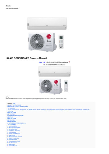
RB-951 MkII Stereo Power AmplifierEnglish21: Controls, Connections, & Internal JumpersPOWER AMPLIFIER RB-951 2LEVEL367812 TRIG INCAUTION49AVIS: RISQUE DE CHOC ELECTRIQUE–NE PAS OUVRIRTO REDUCE THE RISKOF FIRE OR ELECTRICALSHOCK, DO NOT EXPOSETHIS EQUIPMENT TO RAINOR MOISTURE.BRIDGEDMONO10 ASPEAKERSCHANNEL 2CHANNEL SIGNAL OUTPUTLINK1213AC BREAKERPOWER AMPLIFIERMODEL NO. RB-951 MkIIPOWER CONSUMPTION: 200WRB-951P2P3 P1123123123S603S602S604123123S605S606Default Jumper settings shown in illustration.10SIGNAL SENSESTEREO: 4 OHMS MINIMUMBRIDGED: 8 OHMS MINIMUMRISK OF ELECTRIC SHOCKDO NOT OPEN5MkII
32: Hookup (Stereo or Parallel Mono modes)RCA OUTPUTSRL12 TRIG INCAUTIONSIGNAL SENSERISK OF ELECTRIC SHOCKDO NOT OPEN10 AAVIS: RISQUE DE CHOC ELECTRIQUE–NE PAS OUVRIRINPUTCH2CH1WARNING:TO REDUCE THE RISKOF FIRE OR ELECTRICALSHOCK, DO NOT EXPOSETHIS EQUIPMENT TO RAINOR MOISTURE.BRIDGEDMONONORMALSTEROSPEAKERSCHANNEL 2CHANNEL 1OFFCH2BRIDGEDCH1SIGNAL OUTPUTLINKAC BREAKERPOWER AMPLIFIERMODEL NO. RB-951 MkIIPOWER CONSUMPTION: 200WRB-951MkII
RB-951 MkII Stereo Power Amplifier43: Hookup (Bridged Mono mode)RCA OUTPUTSRL12 TRIG INCAUTIONSIGNAL SENSERISK OF ELECTRIC SHOCKDO NOT OPEN10 AAVIS: RISQUE DE CHOC ELECTRIQUE–NE PAS OUVRIRINPUTCH2CH1WARNING:TO REDUCE THE RISKOF FIRE OR ELECTRICALSHOCK, DO NOT EXPOSETHIS EQUIPMENT TO RAINOR MOISTURE.BRIDGEDMONONORMALSTEROSPEAKERSCHANNEL 2CHANNEL 1OFFCH2POWER AMPLIFIERMODEL NO. RB-951 MkIIPOWER CONSUMPTION: 200WRB-951SIGNAL OUTPUTLINKBRIDGED12 TRIG INCAUTIONCH1MkIISIGNAL SENSERISK OF ELECTRIC SHOCKDO NOT OPEN10 AAVIS: RISQUE DE CHOC ELECTRIQUE–NE PAS OUVRIRINPUTCH2CH1WARNING:TO REDUCE THE RISKOF FIRE OR ELECTRICALSHOCK, DO NOT EXPOSETHIS EQUIPMENT TO RAINOR MOISTURE.BRIDGEDMONOAC BREAKERNORMALSTEROSPEAKERSCHANNEL 2CHANNEL 1OFFCH2BRIDGEDCH1SIGNAL OUTPUTLINKAC BREAKERPOWER AMPLIFIERMODEL NO. RB-951 MkIIPOWER CONSUMPTION: 200WRB-951MkII
English5WARNING: There are no user serviceable parts inside.Refer all servicing to qualified service personnel.WARNING: To reduce the risk of fire or electric shock,do not expose the unit to moisture or water. Do notallow foreign objects to get into the enclosure. If theunit is exposed to moisture, or a foreign object getsinto the enclosure, immediately disconnect the powercord from the wall. Take the unit to a qualified serviceperson for inspection and necessary repairs.Read all the instructions before connecting or operating the component. Keep this manual so you can refer to these safety instructions.Heed all warnings and safety information in these instructionsand on the product itself. Follow all operating instructions.Clean the enclosure only with a dry cloth or a vacuum cleaner.You must allow 10 cm or 4 inches of unobstructed clearance aroundthe unit. Do not place the unit on a bed, sofa, rug, or similar surface that could block the ventilation slots. If the component is placedin a bookcase or cabinet, there must be ventilation of the cabinetto allow proper cooling.Keep the component away from radiators, heat registers, stoves,or any other appliance that produces heat.The unit must be connected to a power supply only of the typeand voltage specified on the rear panel of the unit.Connect the component to the power outlet only with the supplied power supply cable or an exact equivalent. Do not modifythe supplied cable in any way. Do not attempt to defeat grounding and/or polarization provisions. Do not use extension cords.Do not route the power cord where it will be crushed, pinched,bent at severe angles, exposed to heat, or damaged in any way.Pay particular attention to the power cord at the plug and whereit exits the back of the unit.The power cord should be unplugged from the wall outlet if theunit is to be left unused for a long period of time.Immediately stop using the component and have it inspected and/or serviced by a qualified service agency if: The power supply cord or plug has been damaged. Objects have fallen or liquid has been spilled into the unit. The unit has been exposed to rain. The unit shows signs of improper operation The unit has been dropped or damaged in any wayPlace the unit on a fixed, level surface strong enough to supportits weight. Do not place it on a moveable cart that could tip over.
RB-951 MkII Stereo Power AmplifierContents6Speakers . 91: Controls, Connections, & Internal Jumpers22: Hookup (Stereo or Parallel Mono modes)33: Hookup (Bridged Mono mode)4About Rotel . 6Getting Started . 7Operating Features7A Few Precautions7Placement7AC Power and Control . 7Speaker Selection9Speaker Wire Selection9Polarity and Phasing9Speaker Connections9Internal Jumper Settingsfor Custom Installation . 10Bypassing the Variable Level Controls(S603 and S604)10Input Sensitivity(S605 and S606)10Selecting Parallel Mono Mode(S602 and P1/P3)10AC Power Input7Power Switch and Indicator7Troubleshooting . 10Auto Turn On/Off Mode Selector7Front Panel Power Indicator Is Not Lit1012V Trigger Input8No Sound10Circuit Breaker8Protection Indicator Is Lit10Protection Indicators8Specifications . 11Stereo/Mono Mode Selection . 8Bridge SwitchandFront Panel Bridge LED8Signal Connections . 8RCA Inputs8Input Level Controls8Clipping Indicators9Signal Output Link9About RotelA family whose passionate interest in musicled them to manufacture high fidelity components of uncompromising quality founded Rotelover 30 years ago. Over the years that passion has remained undiminished and the goalof providing exceptional value for audiophilesand music lovers regardless of their budget,is shared by all Rotel employees.The engineers work as a close team, listening to, and fine tuning each new product untilit reaches their exacting musical standards.They are free to choose components fromaround the world in order to make that product the best they can. You are likely to find capacitors from the United Kingdom and Germany, semiconductors from Japan or the UnitedStates, and toroidal power transformers manufactured in Rotel’s own factory.Rotel’s reputation for excellence has beenearned through hundreds of good reviews andawards from the most respected reviewers inthe industry, who listen to music every day.Their comments keep the company true to itsgoal – the pursuit of equipment that is musical, reliable and affordable.All of us at Rotel thank you for buying thisproduct and hope it will bring you many hoursof enjoyment.
7Getting StartedThank you for purchasing the Rotel RB-951MkIIStereo Power Amplifier. When used in a highquality music or home theater system, your Rotelamplifier will provide years of musical enjoyment.The RB-951MkII is a sophisticated two-channel power amplifier. Discrete output devices,a massive power supply with toroidal transformer, premium components, and Rotel’s Balanced Design ensure superb sound quality.High current capability allows the RB-951MkIIto drive difficult speaker loads with ease.PlacementPower Switch and IndicatorThe RB-951MkII generates heat as part of itsnormal operation. The heat sinks and ventilation openings in the amplifier are designedto dissipate this heat. The ventilation slots inthe top cover must be unobstructed. Thereshould be 10 cm (4 inches) of clearance aroundthe chassis, and reasonable airflow throughthe installation location, to prevent the amplifier from overheating.The power switch is located on the left sideof the front panel. To turn the amplifier on (orto activate either of the optional automaticpower-on modes), push the switch in. The LEDindicator above the switch will light, indicating that the amplifier is turned on. To turn theamplifier off, push the button again and return it to the out position.Likewise, remember the weight of the amplifier when you select an installation location.Make sure that the shelf or cabinet can support its considerable bulk. Again, use commonsense.Operating Features Two-channel Stereo or Bridged Mono operation (back panel switchable) Optional Parallel Mono operation for driving low impedance multi-speaker loads incustom installation applications (requiresresetting internal jumpers). User-selectable power on/off configuration:manual, automatic signal sensing, or controlled by remote 12 volt trigger signal. Front panel input level controls Protection circuitry with front panel indicators Front panel clipping indicatorsA Few PrecautionsPlease read this manual carefully. In additionto basic installation and operating instructions,it provides valuable information on variousRB-951MkII system configurations as well asgeneral information that will help you get optimum performance from your system. Pleasecontact your authorized Rotel dealer for answers to any questions you might have. In addition, all of us at Rotel welcome your questions and comments.Save the RB-951MkII shipping carton and allenclosed packing material for future use. Shipping or moving the RB-951MkII in anything otherthan the original packing material may resultin severe damage to your amplifier.Be sure to keep the original sales receipt. It isyour best record of the date of purchase, whichyou will need in the event warranty service isever required.EnglishAC Power and ControlAC Power InputThe RB-951MkII is supplied with the proper ACpower chord. Use only this cord or an exactequivalent. Do not use an extension cord. Aheavy duty multi-tap power outlet strip maybe used, but only if it is rated to handle thecurrent demanded by the RB-951MkII.Be sure the power switch on the front panelof the RB-951MkII is turned off. Then, plug oneend of the cord into the AC power connectoron the back panel of the amplifier. Plug theother end into an appropriate AC outlet.Your RB-951MkII is configured at the factoryfor the proper AC line voltage in the countrywhere you purchased it (USA: 115 volts/60Hz , Europe: 230 volts/50 Hz). The AC lineconfiguration is noted on a label on the backpanel.NOTE:Should you move your RB-951MkII toanother country, it is possible to configure youramplifier for use on a different line voltage.Do not attempt to perform this conversion yourself. Opening the enclosure of the RB-951MkIIexposes you to dangerous voltages. Consulta qualified technician or the Rotel factory service department for information.If you are going to be away from home foran extended period of time, it is a sensibleprecaution to unplug your amplifier.Auto Turn On/Off ModeSelectorThe RB-951MkII provides three different optionsfor manual or automatic power on/off operation. These modes are selectable using a threeposition slide switch on the back panel asfollows: With the switch in the OFF position,the amplifier is turned on or off manuallyusing the front panel power switch. Alsouse this mode if you are using a switchedAC outlet to control power to the amplifier. With the switch in the SIGNAL SENSING position, the amplifier turns on automatically when a signal is sensed at theinputs. The amplifier will go into standbymode five minutes after no signal is present.The front panel power switch overrides thisfunction. It must be ON for the signal sensingto work. Turning the switch OFF cuts powerto the amplifier, regardless of whether ornot a signal is present. With the switch in the 12V TRIG.IN position, the amplifier is turned onautomatically when a 12 volt trigger signal is present at the screw terminals adjacent to the left of the switch. The amplifierwill go into standby mode if the 12 voltsignal is not present. The front panelPOWER SWITCH overrides this function.It must be ON for the 12V trigger to work.Turning the switch OFF cuts power to theamplifier, regardless of whether or not atrigger signal is present.
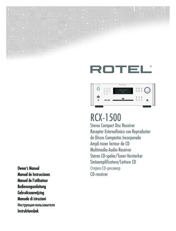
RB-951 MkII Stereo Power Amplifier12V Trigger InputA pair of screw terminals for connecting thewires carrying a 12 volt trigger signal to turnthe amplifier on and off, such as might be usedin an elaborate custom installation. To use thisfeature the adjacent slide switch must be placedto the left position (see previous section).The TRIGGER INPUT accepts any control signal (AC or DC) ranging from 3 volts to 30 volts.The screw terminals are labeled “ and –”Observe proper polarity when connecting thetrigger signal wiring.Circuit BreakerA circuit breaker on the rear panel protectsthe amplifier’s electrical circuity. Generally, thecircuit breaker will only open under a faultcondition which results in excessive currentdraw. To reset the circuit breaker, press thebutton. Should it repeatedly open, contact yourauthorized Rotel dealer for troubleshootingassistance.Protection IndicatorsA thermal protection circuit protects the amplifier against potential damage in the eventof extreme or faulty operating conditions. Unlikemany designs, the RB-951MkII’s protection circuit is independent of the audio signal andhas no impact on sonic performance. Instead,the protection circuit monitors the temperatureof the output devices and shuts down the amplifier if temperatures exceed safe limits.In addition, the RB-951MkII includes overcurrentprotection which operates only when load impedances drops too low. This protection is independent for the left and right channels withseparate front panel PROTECTION LEDS foreach.Should a faulty condition arise, the amplifierwill stop playing and the PROTECTION LEDSon the front panel will light.If this happens, turn the amplifier off, let it cooldown for several minutes, and attempt to identify and correct the problem. When you turnthe amplifier back on, the protection circuitwill automatically reset and the PROTECTIONLEDS should go out.8In most cases, the protection circuitry activatesbecause of a fault condition such as shortedspeaker wires, or inadequate ventilation leading to an overheating condition. In very rarecases, highly reactive or extremely low impedance speaker loads could cause the protection circuit to engage.Stereo/Mono ModeSelectionThe RB-951MkII provides three options forStereo or Bridged Mono operation. Stereo mode: Conventional 2-channelstereo operation. Minimum speaker load:4 ohms. Bridged Mono mode: Serial bridgedmode which more than doubles the amplifier power into a single speaker. Minimum speaker load: 8 ohms. Parallel Mono mode: A special bridgemode that allows the amplifier to driveextremely low impedance speaker loadssuch as might be encountered driving multiple speakers in a custom installation.Minimum speaker load: 2 ohms.The first two modes are selected using a rearpanel switch. The Parallel Mono mode requiressetting internal jumpers and should only bedone by a qualified technician. See the INTERNAL JUMPER SETTINGS section at the endof this manual.Signal ConnectionsThe RB-951MkII provides standard conventionalinput connections — unbalanced RCA typeconnections as found on nearly all audioequipment. In addition, there is a pair of SIGNAL OUTPUT LINK connections for passingthe unchanged input signal on to another audiocomponent.RCA InputsSee Figures 2 and 3These RCA inputs accept audio signals frompreamplifiers or surround sound processors.Use high quality audio interconnect cables forbest performance.For Stereo operation, use both inputs. Connect the left channel output of your preampto the CH 1 INPUT on the RB-951MkII. Connect the right channel of your preamp to theCH 2 INPUT. Make sure that the BRIDGESWITCH is in the NORMAL STEREO position.For Bridged Mono operation, use onlythe CH1 INPUT. Connect one output channelof your preamp to the CH 1 INPUT on theRB-951MkII. Connect the other channel of yourpreamp to a second amplifier. Make sure thatthe BRIDGE SWITCH selector switch is in theBRIDGED MONO position.For Parallel Mono operation, either input may be used. The signal from either willbe sent to all speaker outputs.Input Level ControlsBridge Switchand FrontPanel Bridge LEDA rear panel switch selects Stereo mode orBridged Mono mode.For Stereo mode: Slide the switch to the right,use both input connectors, and connect onespeaker to each pair of speaker connectors.The front panel LED will be extinguished.For Bridged Mono mode: Slide the switchto the left, use only the CH1 INPUT connection, and connect only one speaker to the twoouter speaker connectors. The front panel LEDwill light to indicate Bridged Mono mode.Two recessed controls on the front panel, onefor each channel, provide input level adjustments. These allow you to adjust the gain ofthe amplifier to match other components in anelaborate system. The CH1 level controlchanges the gain of the left channel; the CH2level control changes the right channel.To adjust these controls, use a small, flat-bladescrewdriver. Turn the control clockwise to increase gain. Turn counterclockwise to reducegain.NOTE:These controls may be disabled by resetting an internal jumper.
9Clipping IndicatorsSpeaker Wire SelectionTwo front panel LEDs (one for each channel)flash to indicate when the amplifier is “clipping” or being asked to deliver more outputcurrent than it is capable of delivering. Clipping will cause distortion levels to increase.Use insulated two-conductor stranded wire toconnect the RB-951MkII to the speakers. Thesize and quality of the wire can have an audible effect on the performance of the system.Standard speaker wire will work, but can result in lower output or diminished bass response,particularly over longer distances. In general,heavier wire will improve the sound. For bestperformance, you may want to consider special high-quality speaker cables. Your authorized Rotel dealer can help in the selection ofappropriate cables for your system.Occasional brief clipping on the loudest musical passages is acceptable. However, sustained or frequent clipping is one of the mostcommon causes of speaker damage and shouldbe avoided.Should this occur, either reduce the overall gainof the system by turning down the master volumecontrol on your preamp. Alternatively, you maywish to permanently reduce the gain of theamplifier using the front panel level controls(see previous section).Signal Output LinkThis pair of RCA connections can be used topass the unprocessed input signals to anotheraudio component, for example to “daisy-chain”an additional amplifier to drive a second setof speakers. Any INPUT SIGNAL is also available at these LINK outputs.SpeakersThe RB-951MkII has two pair of speaker connectors, one pair for each channel. These canbe used to connect two loudspeakers in Stereo mode, or to connect one loudspeaker inBridged Mono mode.Speaker SelectionThe nominal impedance of the loudspeaker(s)connected to the RB-951MkII in the variousoperating modes should be: Stereo mode: minimum 4 ohms Bridged Mono mode: minimum 8 ohms Parallel Mono mode: minimum 2 ohmsWhen driving multiple pairs of speakers connected in parallel, the effective impedance theamplifier sees is cut in half. For example, whendriving two pair of 8 ohm speakers, the amplifier sees a 4 ohm load. When driving multiple speakers in parallel, select speakers witha nominal impedance of 8 ohms or higher.Polarity and PhasingThe polarity – the positive/negative orientation of the connections – for every speaker andamplifier connection must be consistent so allthe speakers will be in phase. If the polarityof one connection is mistakenly reversed, bassoutput will be very weak and stereo imagingdegraded. All wire is marked so you can identify the two conductors. There may be ribs ora stripe on the insulation of one conductor.The wire may have clear insulation with different color conductors (copper and silver).There may be polarity indications printed onthe insulation. Identify the positive and negative conductors and be consistent with everyspeaker and amplifier connection.Speaker ConnectionsSee Figures 2 & 3The RB-951MkII has one pair of color codedconnections per channel. Labels above theconnectors show the proper connections forStereo mode. Labels below show the properconnections for Bridged Mono mode.These speaker connectors accept bare wire,connector lugs, or “banana” type connectors(except in the European Community countrieswhere their use is not permitted).Route the wires from the RB-951MkII to thespeakers. Give yourself enough slack so youcan move the components enough to allowaccess to the speaker connectors.EnglishIf you are using banana plugs, connect themto the wires and then plug into the backs ofthe speaker connectors. The collars of thespeaker connectors should be screwed in allthe way (clockwise).If you are using terminal lugs, connect themto the wires. If you are attaching bare wiresdirectly to the speaker connectors, separatethe wire conductors and strip back the insulation from the end of each conductor. Be carefulnot to cut into the wire strands. Unscrew (turncounterclockwise) the speaker connector collar. Place the connector lug around the shaft,or insert the bundled wire into the hole in theshaft. Turn the collars clockwise to clamp theconnector lug or wire firmly in place.NOTE: Be sure there are no loose wire strandsthat could touch adjacent wires or connectors.In Stereo mode: Connect the left speakerto the pair of speaker connectors labeled CH1.Connect the right speaker to the speaker connectors labeled CH2. Follow the labels printedabove the connectors and make sure theBRIDGE MODE switch is set to the NORMALSTEREO position. (See Figure 2)In Bridged Mono mode: Connect the positive terminal of the speaker to the speaker connector labeled BRIDGE . Connect the negative terminal of the speaker to the speaker connector labeled BRIDGE –. Follow the labelsprinted below the connectors and make surethe BRIDGE switch is set to the BRIDGE MONOposition. (See Figure 3)In Parallel Mono mode: Connect the speakers in the same fashion as in the Stereo mode.You can use the connectors for either channel or both – the same output signal is presentat both pair of connectors. (See Figure 2)
RB-951 MkII Stereo Power AmplifierInternal Jumper Settingsfor Custom Installation(see figure 1)There are internal jumpers that can be usedto disable the front panel level controls, to selectone of two input sensitivity settings, and toengage the special Parallel Mono mode fordriving low impedance speaker combinationsin custom installations.WARNING: Removing the top cover of the amplifier to access the jumpers may expose youto potentially dangerous voltages. These settings should only be made by a qualified technician. The AC power cord must be removedfrom the amplifier before the top cover is removed.After removing the top cover, the jumper blockscan be found on the circuit board as shownin Figure 1. Each jumper block has a printedidentification number. The function, ID numbers, and settings for each jumper block areprovided below. To change the setting, placethe jumper on the appropriate pins as indicated.Bypassing the Variable LevelControls (S603 and S604)The front panel Level Controls allow you toadjust the input gain for each channel of theamplifier. These level controls can by bypassedby changing the jumper position on jumperblocks S603 (for CH 1) and S604 (for CH2).To disable the variable level controls:place a jumper across pins 2 and 3 on jumperblock S603 and across pins 1 and 2 on jumperblock S604.To enable the variable level controls:place a jumper across pins 1 and 2 on jumperblock S603 and across pins 2 and 3 on jumperblock S604.10Input Sensitivity(S605 and S606)TroubleshootingJumper blocks S605 and S606 are used toset the input sensitivity of the amplifier.Most difficulties in audio systems are the result of poor or wrong connections, or impropercontrol settings. If you encounter problems,isolate the area of the difficulty, check the controlsettings, determine the cause of the fault andmake the necessary changes. If you are unable to get sound from the RB-951MkII, referto the suggestions for the following conditions:For high sensitivity (0.775v input forrated power): place the jumpers across pins1 and 2 on jumper blocks S605 and S606.For low sensitivity (1.5v input for ratedpower): place the jumpers across pins 2 and3 on jumper blocks S605 and S606.Selecting Parallel Mono Mode(S602 and P1/P3)As described earlier in this manual, the twomost common operating configurations for theRB-951MkII (Stereo mode and Bridged Monomode) are selectable with a back panel switchand require no internal changes.The third configuration, Parallel Mono mode,allows both channels of the amplifier to be combined in parallel. This mode is useful for driving a low impedance speaker load such asdriving multiple speakers in a custom installation.This Parallel Mono mode can be selected onlyby setting internal jumpers (jumper block S602)and changing a buss wire connection (connectors P1and P2).NOTE: it is essential that Parallel Mono modenot be engaged at the same time as Stereomode. This will blow the internal rail fuses.Make sure that you follow all of the instructions below carefully.To convert to Parallel Mono mode:1. Place the jumper across pins 1 and 2 onjumper block S602.2. Locate the buss wire linking the P2 connectorto the P3 connector. Remove the wire fromP3 and move it to the adjacent P1 connector.For Parallel Mono mode, the buss wire mustlink P2 to P1.To return to normal configuration (Stereo or Bridged Mono modes):1. Place the jumper across pins 2 and 3 onjumper block S602.2. Locate the buss wire linking the P2 connectorto the P1 connector. Remove the wire fromP1 and move it to the adjacent P3 connector.For normal mode, the buss wire must linkP2 to P3.Front Panel Power Indicator IsNot LitNo main power to the RB-951MkII. Check ACpower connections at the amplifier and theAC outlet. Check the front panel power switch.Make sure that it is set to the ON position. Ifusing signal sensing auto power-on, make surethat a signal is present at the inputs. If using12V trigger power-on, make sure that a trigger signal is present at rear panel screw terminals.No SoundIf the amp is getting AC power, but is producingno sound, check the PROTECTION INDICATORS on the front panel. If lit, see below. Ifnot, check all of your connections and control settings on associated components. Makesure that your input connections and speakerconnections match your selected stereo/monoconfiguration.Protection Indicator Is LitThe front panel PROTECTION INDICATORSlight when the RB-951MkII protection circuitshave shut off the amplifier. Typically, this occurs only when the ventilation openings areblocked, when there is faulty speaker wiring,or after a period of extreme use. Turn off thesystem and wait for the amp to cool. Then pushthe front panel power switch in and out to reset the protection devices. If the problem is notcorrected or reoccurs, there is a problem withthe system or the amplifier itself.
English11SpecificationsContinuous Power Output Stereo Mode(20-20 kHz, 0.03% THD)50 watts/ch into 8 ohmsContinuous Power Output Bridged MonoMode (20-20 kHz, 0.1% THD)150 watts/ch into 8 ohmsTotal Harmonic Distortion(20Hz-20kHz, 8 ohms) 0.03%Intermodulation Distortion(60 Hz : 7 kHz, 4:1) 0.03%Frequency Response ( 1 dB)15Hz-100kHzDamping Factor (20-20,000 Hz, 8 ohms)280Speaker Impedance (combined load)Stereo mode: 4 ohms minimumBridged Mono mode: 8 ohms minimumParallel Mono mode: 2 ohms minimumSignal to Noise Ratio (IHF A network)116 dBInput Impedance32 k OhmsInput Sensitivity1.5 volt (low setting)0.775 volt (high setting)Auto Turn On Threshold Level (if activated)10 mV input signalAuto Turn Off Delay Time (if activated)5 minutes with no signalPower RequirementsUSA: 115 Volts, 60 HzEurope: 230 Volts, 50 HzPower Consumption200 WattsDimensions (W x H x D)440 x 92 x 334 mm173/8 x 35/8 x 131/4 inWeight (net)6.8 kg, 15 lb.All specifications are accurate at the time of printing.Rotel reserves the right to make improvementswithout notice.
The Rotel Co. Ltd.10-10 Shinsen-ChoShibuya-KuTokyo 150-0045JapanPhone: 81 3-5458-5325Fax: 81 3-5458-5310Rotel of America54 Concord StreetNorth Reading, MA 01864-2699USAPhone: 1 978-664-3820Fax: 1 978-664-4109Rotel EuropeMeadow RoadWorthing, West Sussex BN11 2RXEnglandPhone: 44 (0)1903 524 813Fax: 44 (0)1903 524 831Rotel DeutschlandKleine Heide 12D-33790 Halle/Westf.GermanyPhone: 49 05201-87170Fax: 49 05201-73370082 OMRB-951MkII 113099
an extended period of time, it is a sensible precaution to unplug your amplifier. Power Switch and Indicator The power switch is located on the left side of the front panel. To turn the amplifier on (or to activate either of the optional automatic power-on modes), push the switch in. The LED indicator above the switch will light, indicat-