Transcription
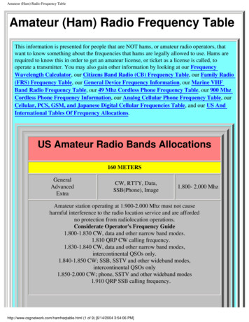
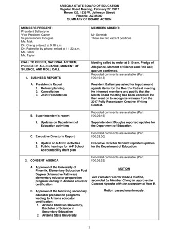
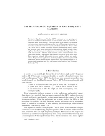
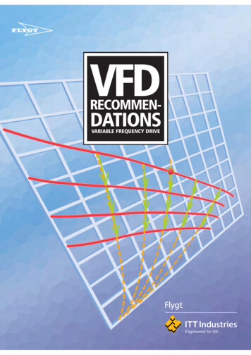
Proceedings of the National Power Systems Conference (NPSC) - 2018, December 14-16, NIT Tiruchirappalli, IndiaIntroduction of Secondary Frequency Control inIndian Power SystemPhanisankar Chilukuri, S.R. Narasimhan, N.Nallarasan, Kajal Gaur, Anamika Sharma, Harish Rathour, S.K.Soonee,and K.V.S.BabaPower System Operation Corporation Ltd. (POSOCO)New Delhi, Indiapchilukuri@posoco.inAbstract — Secondary frequency control has been introducedthrough Automatic Generation Control (AGC) in India in 2018on a pilot basis. This paper elaborates the various steps that wereinvolved in the introduction of secondary frequency control.Details of the important resources identified for theimplementation of AGC at load despatch centre and at powerplants are elaborated. Regulatory framework evolved aroundsecondary frequency control is discussed. The authors alsopresent the core ideas around secondary frequency control andits future in India.control, inertial response and interconnection strength are allessential components of frequency control of any grid. Takingthis experience into cognizance, Central Electricity RegulatoryCommission (CERC) Expert Group to review and suggestmeasures for bringing power system operation closer toNational Reference Frequency (Volume-I) suggestedsecondary control as a vital link in the frequency controlcontinuum as depicted in Figure-2 [2]. No single frequencycontrol mechanism alone is sufficient to stabilize the gridfrequency in a sustainable manner over the icGeneration Control, AGC, Indian power system, Ancillary Services,AGC pilot project.Since independence, Indian power system has evolvedgradually from state grids to regional grids and now an AllIndia synchronous electricity grid. Within each regional grid,the system is operated in a decentralized manner with eachstate grid considered as a notional control area. Unlike thepractices in power systems elsewhere, there was nocompulsion or regulatory mandate for the state control areas tobalance themselves 24 x 7. Rather, the imbalances ordeviations in net drawal from the schedule by each controlarea were priced through a frequency and volumetric linkeddeviation prices. This worked well as long as regional gridsoperated separately and energy deficits were common. Withthe interconnection of regional grids between 2003-2013,introduction of open access and an explosion in the growth ofIndependent Power Producers (IPPs), congestion in thenetwork also came to the fore.I. EVOLUTION TOWARDS SECONDARY FREQUENCY CONTROLIN INDIAOver the years there is a marked decline in the energydeficit [1]. Along with that, there is a significant improvementin frequency profile of the interconnected Indian grid. Figure1 depicts the improvement in average grid frequency profile ofIndia since 2004. Apart from growing grid size andinterconnections, this improvement has been made possiblebecause of bringing multiple frequency control mechanisms inplace supported by strong metering and settlement systems forfinancial accounting. It was observed that each of thefrequency control strategies operate in a different time framewith some overlap. Load and renewable forecast, unitcommitment, generation scheduling, manual frequency controlancillary services, automatic secondary and primary frequencyFigure-1: Average grid frequency of India since 2004978-1-5386-6159-8/18/ 31.00 2018 IEEEWhile primary frequency control is already mandated by theIndian electricity grid code on several generators, slow tertiaryfrequency control as an ancillary service for manuallychanging the schedules of thermal generators was introducedin 2016. Lack of automatic controls for balancing the system,the rapid expansion in Renewable Energy (RE) generation andthe need to successfully integrate these in the grid brought outthe need for automatic secondary frequency control in theIndian grid though this technology is in operation since the1930s as per the 1992 AGC Task force of the IEEE SystemControl sub-committee [3].For a large percentage of time every day, it is observedthat the inter-state shared generating stations have powerreserves available due to non-requisition by the states. Somegenerators are under reserve shutdown due to less requisitionof power from their respective beneficiaries. These reserveshave been envisaged to be harnessed for meeting high demandramps and for minute to minute tracking of load through AGC.
Proceedings of the National Power Systems Conference (NPSC) - 2018, December 14-16, NIT Tiruchirappalli, IndiaFigure-2: Schematic of Reserves, Balancing and Frequency Control Continuum in India [2]CERC identified Primary, Secondary and Tertiary controlsas important components for secure grid operation. A total of3600 MW of Secondary Reserve was decided necessary by theCommission, corresponding to the largest credible unit outagein each region [4][5]. CERC directed Power System OperationCorporation Limited (POSOCO) to submit a detailedprocedure to operationalize reserves in the country. In thisconnection, an outline procedure was submitted in Dec’15.Section IV of the paper discusses the detailed plan foroperationalization of reserves.In the outline procedure, POSOCO proposed to take up apilot project with one of the generating plants in a region toidentify the necessary software and hardware requirements. InJan’16, POSOCO organized brainstorming sessions withstakeholders, experts, Energy Management System (EMS)vendors and load despatchers to assess the requirements forAGC.II.AGC PILOT PROJECTFollowing the discussions, Dadri stage-II power plant (2 x490 MW) in Northern Region (NR) was selected forimplementation of the AGC pilot project keeping in view theease of executing the field level implementation process andconsidering the high probability of reserve availability in thatpower station from historical data.Secondary control considering each of the five regionalgrids in India as a single balancing area was proposed foroperation from National Load Despatch Centre (NLDC),considering the future EMS upgradation project at NLDC.During the course of interaction with the EMS vendors, it wasobserved that that this type of philosophy (Five AGCs locatedat a single control centre) is almost first of its kind. Theconcept of having a region as a balancing area is depicted inFigure-3 and the Area Control Error (ACE) has to be workedout for each area viz. region. The objective of the full-fledgedAGC is to drive the regional ACE to zero. Standard industrialgrade AGC software was used to process the value of ACEand limits of the power plant through the AGC software toderive the plant AGC set point.Regional ACE is calculated using the frequency, interregional schedule tie line MW and actual tie line MW data asshown in Figure-3. The software is capable of operating inthree modes viz., frequency bias, tie line interchange and tieline bias (combination of tie line interchange and frequencybias). References [6] and [7] recommend using frequencyresponse characteristic (FRC) calculated after the after thepower and frequency transients have settled, for the FrequencyBias Setting used in the ACE equation. Twenty events areadequate for estimating the frequency response characteristicto rule out human error [6]. For around 58 events in the gridsince 2015, Frequency response characteristic is archived forall the regions estimated using Phasor Measurement Unit(PMU) data at NLDC.
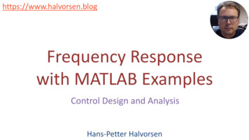
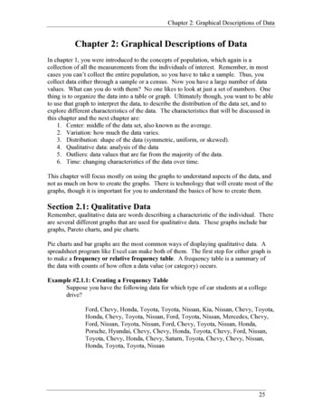
Proceedings of the National Power Systems Conference (NPSC) - 2018, December 14-16, NIT Tiruchirappalli, IndiaThe unit DCS accepts AGC signal sent by NLDC when theunit is set into Remote by the unit operator. Similarly the unitDCS only receives the signal but does not act on the signalwhen the unit is placed in Local. Unit circuit breaker status isalso collected by the AGC system to update the limits if anyunit goes offline.There are two modes OFF and ON. When workingnormally, AGC is in ON state. In case the tie line MW datathat is telemetered from the Remote Terminal Units (RTUs) issuspect for more than ten minutes, then the AGC programtranscends to mode OFF. AGC program has to be switchedON manually after the quality of telemetry is restored. Also, ifthere is any break detected in the communication channels toAGC server at NLDC, then the AGC program goes to OFFstate.Figure-3: Concept of region as a balancing areaData is exchanged between the SCADA system at NLDCand AGC application through Inter Control CenterCommunications Protocol (ICCP). AGC system at NLDCexchanges data two-way with the power plant in IEC 60870-5104 (IEC 104) protocol. The data flow in AGC project isrepresented in Figure 4.Unit Load Set Point (ULSP) of Dadri Stg-II is the gross setpoint of the plant including auxiliary power consumption,which is fed manually by the plant operator to the unit DigitalControl System (DCS). This is taken as an input for the AGCto establish the reference for base set point. AGC softwareoutput is the plant AGC set point which is communicatedevery two seconds (configurable 2s-10s) to the power plant.Figure-5: Architecture of the AGC pilot projectThe architecture of the project is depicted in Figure-5. AGCserver at NLDC has four divisions. They are - i) ICCP block,ii) database block, iii) front end processor block and iv) AGCblock. ICCP block handles the data exchanges with SCADA. Database block contains the information regarding theparameters of the units under AGC. Front end processor communicates with the RemoteTerminal Unit (RTU) located at the plant under AGC. AGC block handles the Proportional Integral (PI)controller related calculations and the power plant limitsafter taking inputs from other blocks and decides the plantAGC set point.Figure-4: Data flow in AGC pilot projectDelta P is the AGC correction calculated as the differencebetween plant AGC set point and the reference ULSP. Theplant operator has the choice to distribute the plant AGC setpoint in between the two units by a Factor.RTU located at the plant is connected to the nearest wideband communication node through a fibre optic cable laid as apart of the AGC project. The nearest wide bandcommunication node reports to the AGC front end processorlocated at NLDC through a communication path provided bythe optical fiber ground wire (OPGW) cables of the meshedelectric grid planned by Central Transmission Utility (CTU).RTU located at the plant is hardwired to the generating unitDigital Control System (DCS). Cyber security is ensured
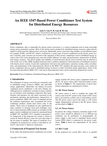
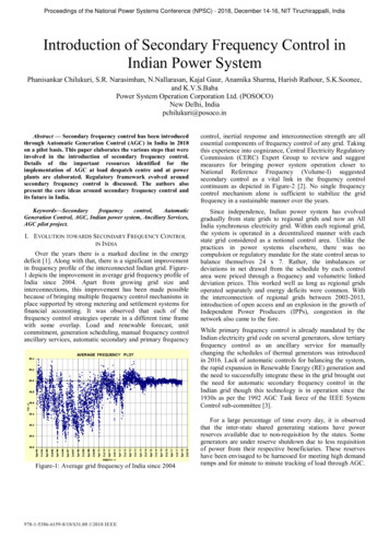
Proceedings of the National Power Systems Conference (NPSC) - 2018, December 14-16, NIT Tiruchirappalli, Indiathrough appropriate router configurations, firewalls andantivirus softwares.Desired attributes of the RTU are also understood as a partof the pilot project. They are listed hereunder. Sizing of the analog and digital input cards are decidedbased on the number of signals sent and received pergenerating unit for AGC, with scope for expansion. In the first AGC Pilot, no digital outputs were used, butprovision was kept for connecting digital devices infuture. The RTU should be capable of communicating over IEC60870-5-104 protocol with RLDC/NLDC. RTU should also have the capability of performingmicroprocessor level calculations and accepting logic. Inthe AGC pilot, arithmetic and logical operations like ,,*, /, if, else, while, do, AND, OR etc. were used on AGCsignals for sanity checking of data. GPS clock synchronization facility, operation over thestandard DC input voltage of 24-60 V DC, capability ofautomatic start up following restoration of power after anoutage, internal battery backup to hold data and date/timestamp in sequence of events (SOE) buffer memory isneeded. Communication interfaces should be via insertable serialinterface modules for Ethernet. The RTU shall be able to store the AGC signals fromNLDC/RLDC and mathematically integrate the AGCcommand over the desired period along with GPS timestamping for accounting purposes.A mock test was successfully conducted in June’17 byconnecting NTPC Dadri stg-II with NLDC through AGC.During the test, signals were sent every two seconds(configurable between 2s-10s) directly from NLDC controlcentre in New Delhi to NTPC Dadri control centre. Thegenerator responded as per the requirement. Response of theplant during mock test is shown in Figure-6.Figure-6: Results of the AGC mock testRamp limits of the plant were restricted in the software to /- 10 MW/min during the test. It was observed that the outputof the software had strictly honored the limits. Ramp rateadherence of the plant AGC set point is shown in Figure-7.Other important limits like max-min limits of the generatingunits are also strictly honoured.CERC in its order in Dec’17 approved the Commissioningof the AGC Pilot Project between NLDC and NTPC DadriStage-II [8]. The Commission observed that development ofsecondary reserves in the country will lead to grid security andreliability. The Commission also directed that similar pilotprojects may be replicated by NLDC, in at least one otherregional grid of the country.Figure-7: Ramp rate of the plant AGC set pointThe country’s first AGC set up at NTPC Dadri stg-II andNLDC has been successfully operationalized from Jan’18.Further areas from the pilot such as frequency bias modeoperation, frequency plus tieline bias mode operation besidesconfiguring additional units on AGC is also being studied.III.METERING, ACCOUNTING AND SETTLEMENT OFSECONDARY CONTROL SERVICESWhile several methods exist worldwide for compensatinggenerating stations providing secondary regulation servicesthrough AGC considering opportunity costs, a simple methodis required considering that the power plant is under CERC’sjurisdiction as far as tariff is concerned, its fixed cost liabilityis being shared by the beneficiaries and little opportunity costis involved in bringing this plant under AGC.Accounting and settlement of energy and services is beingdone as per the orders of the regulatory commissionmentioned above. Schematic of signals archived foraccounting and settlement is given as Figure-8. AggregatedDelta P MW signals over 15 minutes and 5 minutes are loggedin MWh at NLDC and power plant as AGC MWh. Power plantsends its AGC MWh account every week to NLDC for crossverification. AGC MWh logs are forwarded to NorthernRegional Power Committee (NRPC) secretariat on weeklybasis through Northern Region Load Despatch Centre.
Proceedings of the National Power Systems Conference (NPSC) - 2018, December 14-16, NIT Tiruchirappalli, IndiaDeviation in MWh for every 15-minute time block wouldbe worked out asPant MWh deviationPlant Actual MWhPlant Scheduled MWhThe markup of 50 paise/kWh was arrived at considering thehalf yearly feedback on Ancillary Services submitted to CERC[10]. Based on the experience with the implementation ofAncillary Services, it was observed that the generatorsparticipating in the Ancillary Services were retainingapproximately 50 paise/kWh as incentive on an average afterall payments as per the Ancillary Service regulations [11]. Thesecondary control energy account is prepared by the RegionalPower Committee (RPC) on weekly basis along withDeviation Settlement Mechanism (DSM) Account and theReserve Regulation Ancillary Services (RRAS) account.There are no opportunity charges payable to the secondarycontrol generators as only the unused power reserves are beingused for AGC.IV.IMPLEMENTATION PLAN FOR SECONDARY FREQUENCYCONTROLFigure-8: Schematic of the metering and accounting systemPlant Actual MWh & Plant Scheduled MWh are alwayspositive. AGC MWh can be either positive or negative. ThisPlant MWh deviation would be settled as per the existingDeviation Settlement Mechanism (DSM) Regulations [9]. Forpositive AGC MWh computed during every 15-minute timeblock, energy charge payment would be made from theregional DSM pool to the power plant. For negative AGCMWh, which means reduction in generation from thescheduled set point, computed during a 15-minute time block,power plant shall pay as per the same variable charges aboveto the regional DSM pool. For AGC MWh computed for each5-minute time block, 50 paise/kWh mark-up is being paid topower plant from regional DSM pool for both positive AGCMWh and negative AGC MWh. Same is depicted in Figure-9.Figure-9: Payment mechanism for secondary control servicesA detailed plan was submitted to CERC by POSOCO inJuly’17 for the implementation of secondary frequencycontrol. Secondary Control was recommended to be added asan Ancillary Service [12]. As per the detailed plan, all theISGS generators whose tariff is regulated / adopted by CERCwill be brought under secondary control in the first phase(Phase-I). It was observed from historical statistics thatNorthern Region (NR) and Western Region (WR) haveconsiderable un requisitioned surplus on bar in their ISGS for90% of the time. Substantial generation capacity addition isexpected in Southern Region (SR) in the near future. Toimprove the availability of Reserves all Regional Entitygenerating stations scheduled by RLDCs over and above thephase-I power stations are proposed to be brought undersecondary control in phase-II.Considering the excellent controllability of powerelectronic devices and the nominal cost of the AGC setup, REresources like wind and solar also might be wired for AGC.This would be useful for regulation in cases of extremedispatch scenarios when system runs out of secondary reservesand/or emergencies if RE is to be curtailed. Tehri Pumpedstorage plant may also be operational by 2019 and it can alsobe included in the AGC project. In case of the generatorswhich are part merchant and part regulated in India, toparticipate in the secondary control process, it wasrecommended that they shall share their Declared Capabilityand total schedule like other ISGS generators on a day aheadbasis. Subsequent revisions in the same must also be sharedwith RLDCs. The generating units should have workingcontrol systems for turbine, boiler and governor to participatein the present AGC mechanism. Governor responseplots/graphs of past incidents have to be submitted to RLDCas a proof. The existing communication backbone fromNLDC/RLDC to the nearest wideband node has to be madeavailable through coordination with Central TransmissionUtility (CTU). IEC104 protocol will be used for two waycommunication from RLDC/NLDC to the plant unit controlsystem in the AGC project. Data is being transferred till date
Proceedings of the National Power Systems Conference (NPSC) - 2018, December 14-16, NIT Tiruchirappalli, Indiathrough IEC 101 protocol to RLDC/NLDC from the field.Cyber Security will be ascertained through appropriate routerconfigurations, firewalls and antivirus software.With regard to AGC at state level, report of CERC ExpertGroup [2] suggests that AGC at the intra state level,particularly for large and renewable rich states, can beimplemented in line with directions by the State ElectricityRegulatory Commissions (SERCs). Forum of Regulatorsapproved SAMAST report [13] for intra-state accounting andsettlement system. A robust metering, accounting andsettlement system is a must to implement any ancillaryservice. Investment for the envisaged implementation of AGCis minor considering the impact AGC shall have on frequencyand grid security of Indian power system. The total cost of theproposed implementation is comparable to 1/10th (one tenth)of the indicative cost of a 765 kV double circuit transmissionline of 300 km length. Secondary control is suggested to be afast response Ancillary Service, which will become anadditional revenue stream for the conventional generators afterlarge scale penetration of renewables.After successful testing and implementation, thistechnology is planned to be spread across India for around 100power generation plants. A total of around 65000 MW isenvisaged to be brought under AGC. The full scale project,planned by 2022, shall enable efficiency and grid security inthe India power system, making it ready to handle the 175 GWof renewables targeted by 2022. It is felt that even if thesecondary frequency control service is procured from themarket at a later date, the generators need to be ready with thenecessary infrastructure. NLDC SCADA upgradation startedfrom Oct’17 and is scheduled to be completed by mid-2019.AGC integration work involving software modelling,hardware and communication work also has to be done inparallel. NLDC AGC set up by 2021-22 is envisaged to becapable of sending and receiving AGC signals to all theRegional Entity generating stations to start with, for the firsttime in India.V.CONCLUSIONAll the frequency control strategies should be given equalimportance. Successful implementation of secondaryfrequency control in India requires several resources. Softwareand hardware at plant and load dispatch center are a must. Astrong metering, accounting and settlement system is essentialsupported by regulations. Incentive for participating insecondary frequency control is recommended for gatheringpower reserves. Lastly, regulatory support for all the aboveactivities enables hassle free implementation and operation.Different agencies are involved in the full project, whichmakes the implementation of secondary control in Indiaunique.ACKNOWLEDGMENTThe authors are grateful to CERC, NTPC, POSOCO, CEA,RPCs and the EMS vendors for their support during theproject. A special word of gratitude to Professor Anjan Bose,FIEEE, Regents Professor, WSU for the continuous discussionand debate over a decade which had been a source of constantinspiration to the authors as they went about implementing theproject. The views expressed in this paper are those of theauthors and not necessarily of the organization they belong to.REFERENCES[1] Growth of Electricity Sector in India from 1947-2017,Central Electricity Authority, May 2017. ing/pdm/growth2017.pdf[2] Report of CERC Expert Group to review and suggestmeasures for bringing power system operation closer toNational Reference Frequency (Volume-I). [online]http://cercind.gov.in/2018/Reports/50%20Hz Committee1.pdf[3] N. Jaleeli, L. S. VanSlyck, D. N. Ewart, L. H. Fink and A.G. Hoffmann, "Understanding automatic generationcontrol," in IEEE Transactions on Power Systems, vol. 7,no. 3, pp. 1106-1122, Aug. 1992.[4] Central Electricity Regulatory Commission, Report of theCommittee On Spinning Reserve, 17th September, /Annexure%20SpinningReseves.pdf[5] CERC order on Roadmap to operationalise Reserves inthe country, October, 2015. [online]http://www.cercind.gov.in/2015/orders/SO 11.pdf[6] IEEE Task Force Report. 2017. “Measurement,Monitoring, and Reliability Issues Related to PrimaryGoverning Frequency Response,” Technical Report PESR-24, October.[7] P. Kundur, Power System Stability and Control, Chapter11, McGraw-Hill, New York, 1994.[8] CERC order in the matter of Automatic GenerationControl (AGC) pilot project. [online]http://www.cercind.gov.in/2017/orders/79 rc.pdf[9] Central Electricity Regulatory Commission (DeviationSettlement Mechanism and related matters) Regulations,2014. noti132.pdf[10] Reserve Regulation Ancillary Services (RRAS)Implementation in Indian Grid - Half Year Analysis andFeedback by POSOCO, November, 2016. ack-tocerc/?wpdmdl 8916[11] Detailed Procedure For Ancillary Services Operations,POSOCO, March 2016. pdf[12] Detailed Modus Operandi on operationalization ofSpinning Reserves by POSOCO, July 2017. /?wpdmdl 13461[13] Forum of Regulators ‘SAMAST’ Report. hatsNew/SAMAST.pdf
AGC server at NLDC, then the AGC program goes to OFF state. Figure-5: Architecture of the AGC pilot project The architecture of the project is depicted in Figure-5. AGC server at NLDC has four divisions. They are - i) ICCP block, ii) database block, iii) front end processor block and iv) AGC block. ICCP block handles the data exchanges with .