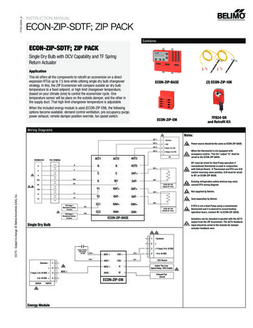
Transcription
WARNING!Before replacing actuator, damper must be inspectedand determined to be fully functional. See damper checklist below underNFPA 80 & NFPA 105.Pottorff Siebe MA2xx Replacement with Belimo FS SeriesContentsUL .2Code and Standard Issues.2NFPA 80 (Fire) & NFPA 105 (Smoke) .3Local Code Approval .4Cross Reference .5Examples of various gear train motors and mounting .6MA2xx with blade switches .6Transition model variation .8Linkage mounting.18Miscellaneous parts .19Auxiliary Switches .20Thermal sensor replacements – BAE165 US .21Wiring .21Building Official / Fire Marshal Notification Form. .24Contacts:Chris Sheehan 203 749-3112Larry Felker 775 355-2461 (775 250-4160 Cell)Mike Knipple 203 749-3170Laure Pomianowski 775 355-2466800 543-9038WARNING!Installer must be trained and experienced with repairof fire and smoke dampers and actuators.www.belimo.us/firesmokePottorff MA2xx Replacement with Belimo FS SeriesMarch 20181
UL In the “Marking & Application Guide, Dampers for Fire Barrier and Smoke Applications &Ceiling Dampers” April 2013 by Underwriters Laboratories Inc. , page 6 they state:DAMPER ACTUATORS“ field mounting or substitution of actuators is not covered within the scope of the ULcertification of the product. However, this does not necessarily preclude replacement ofactuators in the field. Like any appliance, field servicing of these products is not coveredunder the scope of the UL certification and factory follow-up service program. As with anypart of the damper, it is expected that replacement of actuators in the field be done inaccordance with the damper manufacturer’s normal field servicing program.”Code and Standard IssuesIn general, the administrative section of codes state that all mechanical and electrical systemsmust be kept in working order and an individual section may state that all life safety devicesand systems must be operable. NFPA 80 (Fire) & NFPA 105 (Smoke) require periodic testingand repair of dampers as soon as possible after any deficiency is uncovered.Chapter 7 IBC & IFC "Containment” DampersCommissioningEnd of first yearEvery 4 years except in hospitals every 6 yearsChapter 9 IFC "Smoke Control System” oningSemi-annuallyAnnuallyChapter 9 IBC & IFCFire detection & Smoke control systemsDedicatedWeekly self-testNon-dedicatedNot requiredFire & smoke dampers are appliances and field replacement of components is required whenfailure of any component occurs.The Authority Having Jurisdiction (local Fire Marshal and/or Building Official) must beconsulted if any blade or auxiliary switches are employed and are connected to the fire alarmsystem or to a Fire Fighters Smoke Control System (FSCS) panel. Retesting is required. Apermit and inspection may be required since connections to an alarm system have beentouched.Pottorff MA2xx Replacement with Belimo FS SeriesMarch 20182
NFPA 80 (Fire) & NFPA 105 (Smoke)NFPA requires damper inspection and repair of dampers.See www.nfpa.org. for Standards.See NFPA 80 & NFPA 105 for details. The damper cleaning and examination checklist here is based on them.Damper installation shall meet code requirements. Fire stopping and drywall integrity shall beconfirmed. Damper blades shall be in plane of wall. Duct shall be fall away with no fastenersconnected to damper sleeve.a. Dampers and ducts shall be cleaned of all foreign debris and dust build-up.b. All exposed moving parts of the damper shall be dry lubricated as required by themanufacturer. Do not use oil as it draws dirt.c. Damper shall be examined without defective old motor or new actuator to determine:i. The damper shall fully close from the open position.ii. Damper shall fully open from the closed position.iii. There are no obstructions to the operation of the damper. The damper shall not beblocked from closure in any way due to rusted, bent, misaligned, or damaged frameor blades. The damper shall not have defective hinges, side &/or blade seals, orother moving parts. The damper frame shall not be penetrated by any foreignobjects that would affect operation.d. If the damper is equipped with a fusible link, the link shall be removed for testing to ensurefull closure and lock-in-place if so equipped. If the link is damaged or painted, it shall bereplaced with a link of the same size, temperature, and load rating.e. The fusible link shall be reinstalled after testing is complete.After installation and wiring of new actuator it shall be tested.a. The checklist may be customized using material here and in NFPA Standards. Multiplegeometric configurations of springs, fusible link, thermal sensor(s), and actuation are possible.Confirm with AHJ if any additional requirements exist.b. Electric thermal sensors, if present, must be tested and replaced if defective.c. The test shall be conducted with normal HVAC airflow.d. When equipped with smoke detection activation, the smoke detector shall be activatedand damper operation observed.A record of all repairs must be kept and made available to AHJ.Test voltage input to actuators and repair as necessary if voltage is not correct.Old breakers often deliver below 115V and failed actuators may be due to powersupply problems.For the Air Movement and Control Association damper maintainance manual go to:http://www.amca.org/publications/damper maintenance.aspxPottorff MA2xx Replacement with Belimo FS SeriesMarch 20183
Local Code ApprovalWhile it is not detailed in codes, the following rules should be followed for selecting Belimoactuators for replacement:Check the technical specifications to ensure an “equal or better” actuator is used. Temperature – the replacement actuator shall have been UL555S tested at the same orbetter temperature as the original actuator. 250 F or 350 F are standard. (Code is250 F. However, in engineered smoke control systems the consulting engineer mayhave required 350 F. Tunnels and some other applications require highertemperatures.) Time – the replacement actuator shall drive open and spring closed at a speed equal orfaster than presently required by codes. ( 75 seconds is UL 555S and most codes.Las Vegas is 60 seconds. Consult the AHJ with any questions.) Torque – replacement actuator shall have equal or greater torque than the failedactuator. Voltage – replacement actuator shall have the same voltage rating as the original. Amperage – the replacement actuator(s) shall not draw more amperage than theoriginal(s) and cause the total connected amp draw on a circuit breaker to be greaterthan allowed by electrical code. (This is not a problem as Belimo actuators draw verylow current.) Final Testing – actuated damper and associated devices shall be tested for properoperation. See Acceptance testing details below.(Mnemonic device: TTT-VAT)WARNING!In all cases, installation must comply with any and all local electricaland life safety codes. Operation of the system after installation mustbe performed to verify proper damper cycling. Final checkout requiresverifying correct function.WARNING!Note that where any fire alarm wiring is touched, the fire departmentmust be informed.Pottorff MA2xx Replacement with Belimo FS SeriesMarch 20184
Cross ReferenceFor greater detail see www.belimo.us/firesmoke RETROFIT or download fromhttps://www.belimo.us/mam/americas/technical documents/pdfweb/fire and smoke doc/fire smoke competitive replacement data reference.pdfBarber 0120 VACMA221240 VACMA22324 VACMA230120 VACMA231240 VACMA23324 VACMA240120 VACMA250120 VACMA251230 VACMA25324 VACMA-31824 05050505050AuxSwitchesBelimoFSLF120 USFSLF230 USFSLF24 USFSNF120 USFSNF230 USFSNF24 USFSNF120 USFSNF230 USFSNF24 US60FSNF24 USFSNF24 -S24 VAC601US120 VAC60FSNF120 USFSNF120-S120 VAC601USDirect couple the Belimo where shaft is available.Some were direct coupled.FSTF 1.5 sq.ft. FSLF 4sq.ft.FSNF 12 sq.ft. FSAF*A 18 sq.ft.Notes1, 2, 41, 2, 41, 2, 41, 2, 31, 2, 31, 2, 35,61, 2, 3, 41, 2, 3, 41, 2, 3, 41, 31, 31, 31, 3For Pottorff with shaft spring see:https://www.belimo.us/mam/americas/technical documents/pdfweb/fire and smoke doc/pottorff-ma2xx to belimo.pdfMotor was not 90 degree and pulley and cable were usuallyused. Some geometric changes are necessary to simplify.Provide photos. Motor, linkage, blades, fusible link, McCabe Link, Typically direct couple to damper shaft if available.Otherwise, investigation necessary.4 sq.ft. in general for the FSLF. 36” w x 24” h is also UL555S listed with Pottorff.On MA318/418 -500 indicates aux switches. Use –S Belimo models.Where linkages required due to geometry of installation, use FSNF. FSLF does not havelinkages. FSNF is UL555S listed on 2 sections up to 16 sq.ft. Call Pottorff for dimensions.Pottorff MA2xx Replacement with Belimo FS SeriesMarch 20185
Nominal sq.ft. per UL555Stesting.Sq.ft. 1.5 4Temp250 F350 FActuatorFSTFFSLF 6121612350 F350 F250 F350 FFSLFFSNFFSNFFSAF*A.36” x 24” OK, not 24” x36”Call for dimensions.Examples of various gear train motors and mountingIn general, oil-filled spring return motors like the MA418 are straightforwardreplacements. In this case, the Belimo FSNF or FSAF may be direct coupled. The shaft springshould be examined and exercised to prove it is still operational. The fusible link cannot beseen, however it should release the shaft spring.For a cross reference or more retrofit instructions see Retrofit or Documentation Tabs inmiddle of ottorff MA2xx Replacement with Belimo FS SeriesNovember 20176
MA2xx with blade switchesBelow is the common shaft spring with fusible link model. It has the less commonblade indication switches. Since the switches go back to the fire alarm system, smokecontrol panel, or fire fighters’ smoke control (FSCS) panel, and they are modified here,retest of the system must be performed. A Belimo –S model could be installed to avoidthe blade switch adjustment problems which frequently occur.Shaft spring. This closesdamper when the motor isunpowered.MA230On some models therewas a spring on theoutside instead of ashaft spring. Notshown here.Bolt holds. springThe fusible linkreleases the motor.and slams damperblades closed.Rod connects to two switchesinside the wiring box. These areposition indication for FireFighters’ Smoke Control Panel.Pottorff MA2xx Replacement with Belimo FS SeriesBlade indicationswitchesNovember 20177
Transition model variationThe picture below shows a “transition” model between the older fusible linkversion and the modern Belimo spring return version. There are electrical thermalsensors instead of a fusible link. The steps shown in the main body of this installationinstruction do not apply.In this case, simply unhook the shaft spring making sure it cannot bind. Thenreplace the actuator and wire according to the diagram(s) in the wiring section.A dualthermal sensor can be seen at the lower left so this application is a reopenable damper.The spring must be disabled otherwise the Belimo FSLF would have to driveagainst its own spring as well as the shaft spring.DualSensorsNo fusiblelinkThere are no switches although there are two sensors appearing here. It may be thatonly one sensor is used. Investigate operation of fire fighters’ smoke control (FSCS)panel. Retest notifying fire department if necessary.INSTRUCTION SHEET - Pottorff MA2xx Replacement with Belimo FS SeriesOct 20148
Step by Step Replacement InstructionsThe MA220, 230, 250, 253 and similar actuators can be replaced by either of the Belimo FSLF120/24 orthe FSNF120/24 provided the following conditions are met:1. If the damper is equipped with an HS-10 or a DRS-30, the spring used on the MA250/253 set-up mustbe disconnected so as not to interfere with the operation of the Belimo actuator.2. If the damper is equipped with a fusible link, the link must be removed and replaced with a blank (or thefusible link arm can be bolted to the jackshaft) and the shaft spring must be disconnected so as not tointerfere with the operation of the Belimo actuator. IN ADDITION, a Pottorff HS-10 or Belimo BAE165must be installed on the damper and wired to the Belimo actuator per drawings in Wiring below.More modern dampers are electric thermal disk sensing only and the HS-10 is already present.In that case, replacement and testing of the actuator does not require spring disconnection.1. Disconnect incoming power and wiring at junction box or actuator.Tag all wires.2. Remove old actuator and mounting bracket.3. Mount Belimo FSNF or FSLF depending on torque or function required4. Reconnect wiring per original drawing. Typical wiring shown on p9.5. Restore incoming power.6. Test all functions per Fire Marshal Form on p10.DETAILED INSTRUCTIONS ON REMOVAL OF FUSIBLE LINK, DISABLINGJACKSHAFT SPRING, AND HS10 INSTALLATION FOLLOW.WARNING!Disconnect and lock out power before starting to disconnect old motor.WARNING!Anti-rotation strap may not be attached to the duct. It is attached to thedamper sleeve or to a flat plate secured to the damper or sleeve.The duct must be free to fall away leaving the damper in the wall.INSTRUCTION SHEET - Pottorff MA2xx Replacement with Belimo FS SeriesOct 20149
1. Detach actuator from jackshaft2. Remove the actuator-mounting bracket and loosen setscrews3. Remove old motor.Notes:Pottorff MA2xx Replacement with Belimo FS SeriesMarch 201810
4. Remove the e-ring where knee lock attaches to the drive blade bracketWARNING!USE CAUTION!SPRING IS UNDER HIGH TORSION AND MAY CAUSE SERIOUS INJURY!5. Disconnect knee-lock6. Carefully unwind spring.The spring should no longer affect the damper. It must be disconnected so it is not anobjectionable extra load on the actuator.Pottorff MA2xx Replacement with Belimo FS SeriesMarch 201811
7. Insert knee lock pin back into drive blade bracket8. Secure knee lock to drive blade bracket with e-ring9. If a fusible link is on the damper, insert a 5/16” x 1-1/2” carriage bolt into the spring arm.DO NOT REMOVE THE OTHER BOLT.Pottorff MA2xx Replacement with Belimo FS SeriesMarch 201812
10. Shaft spring is disconnected. Actuator life span is shortened if it must drive against thisunnecessary extra torque load.11. Inspect your actuator. The clamp must be on the CW side.Double check that actuator springs damper closed.12. If the clamp is not on the CW side, remove the clamp and reinstall on the CW sidePottorff MA2xx Replacement with Belimo FS SeriesMarch 201813
13. While reinstalling the clamp, line up the indicator to zero position marked on the actuator14. Slide the actuator over the jackshaft with the clamp outward.15. Finger tighten the nuts16. Attach the anti-rotation strap. It must not be completely tight and jammed into the slot onthe actuator. The strap may not be connected to the duct since the duct must be able to fallaway.17. Tighten the bolts. Teeth in cold-weldclamp dig into shaft.Pottorff MA2xx Replacement with Belimo FS SeriesMarch 201814
If convenient for wiringconnections, attach awiring box to the Belimoconduit connector with a½” chase nipple.18. Position the HS10 near the actuator and mark its location19. Make an 11/16” hole where the electroniclink will be positioned20. Mount the HS10 onto sleeve by inserting the electronic link into the 11/16” hole.Secure with #10x1/2” screws.21. Wire the HS10 electric thermal sensor and the actuator in series with the hot wiregoing into the HS10 first.See Typical Fire-Smoke Combination Damper in Wiring section below.Pottorff MA2xx Replacement with Belimo FS SeriesMarch 201815
Distance at top must bethe same as at bottomActuator must beperpendicular to thedamper shaft.Figure 1Actuator should beparallel to the plane ofthe damper frame andsleeve.Allow any non-concentric shaftmotion to be taken up bymounting stud in middle of U-slotNote how the pin of the antirotation strap is mounted inmiddle of actuator U-slot.Figure 2This is acceptable as longas mechanically solid.As long as it is mechanicallysolid, the anti-rotation strapmay be bent to fit height.Figure 3-Pottorff MA2xx Replacement with Belimo FS SeriesMarch 201816
Short shaft mountingFor short shaft mounting, theZG-LMSA-1/2-5 can beused. Alternately, the clampcan be installed between theactuator and sheet metal.ClampFSLF mounted on thedamper shaft. Twosheet metal screws holdthe anti-rotation strap.Two nuts secure coldweld clamp onto shaft.FSNF mounted on thedamper shaft. Two screwshold the anti-rotation strap.Two nuts secure cold-weldclamp onto shaft.FSAF mounts the same.Note that actuator floats freely. Clamp cold welds when teeth dig into the dampershaft and the anti-rotation strap stud allows the actuator to move if shaft is not perfectlyconcentric. Rigid mounting by jamming the stud into the U-slot of actuator is NOT usuallybest.WARNING!Read Data Sheet provided in box with eachactuator for specific wiring details.Pottorff MA2xx Replacement with Belimo FS SeriesMarch 201817
Linkage mountingPossible alternate arrangements for damper clip. (FSNF, FSAF actuators shown.)Belimo linkage ical documents/data sheets/man-airacc/Mechanical Accessories.pdfMounting Methods Guide:https://www.belimo.us/mam/americas/technical documents/pdfweb/guides/mounting methods.pdfPottorff MA2xx Replacement with Belimo FS SeriesMarch 201818
Miscellaneous partsShould they be needed, Belimo carries a range of parts. Ball joints and 5/16”rods are available from most distributors.Where the crank arm on the jackshaft is broken ornot of the type needed, the KH12 fits over theshaft without removing it. Zinc plated steel. Slot isfor the KG10A ball joint. V-bolt fits ¾” to 1” (20 to25mm) shafts.KH-6. Zinc plated steel. For shafts 3/8” to 11/16”Uses KG6 ball joint. Slot width 1/4”KH-8. Zinc plated steel. For shafts 3/8” to 11/16”Uses KG8 (90 degree) or KG10A ball joint. Slotwidth 21/64”KH8KG8 3/8”KG6, KG10A ¼”SH8 (not shown – see picture page 9). Push-rod for KG6 & KG8 ball joints. 5/16” 36” longUse SH10 3/8” rods for GMB and dual FSAF or FSNF linkages. 5/16” can bend under heavyloads.ZG-DC1 Damper blade clip and ball joints for blades typically3.5” in width. Typically the actuator or rod to shaftis in front of blade.ZG-DC2 Damper blade clip and ball joints – typically used for 6” wideblade control dampers. Typically the ctuator or rod toshaft is above or below the damper.Pottorff MA2xx Replacement with Belimo FS SeriesMarch 201819
Auxiliary SwitchesDamper blade switch assemblyExternally mounted auxiliary switchesWhere the original switches for signaling position to a Fire Fighters’ SmokeControl Panel or to local indicator lights must be replaced or are inoperativethe Belimo –S model actuators may be used or a S2A-F may be installed.Belimo S2A-F.FSLF (mid 2014ff), FSNF, andFSAF actuators can use theadd on switch package.-S models165 FHH CManualresetSome models are SPDT.Check data sheets.CInternal switchesS1S2Contact closed if Contact closes ifdamper closed damper openSwitchcableClosedPottorff MA2xx Replacement with Belimo FS SeriesHotMarch 2018Open20
Thermal sensor replacements – BAE165 USOriginal equipment is recommended although not strictly required by code. UL does notregulate replacement or repair. See NFPA 80 or NFPA 105. Pottorff’s thermal switch ispart number HS10. Belimo’s version is shown below.Belimo BAE165 USWhere existing sensor isdefective or one must beadded, the 165 F primarysensor may be used.WiringBelimo Mechanical165 FThermodiscAnti- rotationstrapFSLFFSNFWhere a junction box isrequired a chase nipple andbox may be mounted on theBelimo conduit connector.½” threadedconnectorChase nipple2x 4 box andblank coverExisting flex connector andincoming power wiresPottorff MA2xx Replacement with Belimo FS SeriesMarch 201821
The wiring below is how the original damper was most typically wired. Most often, thewiring will have to be modified to appear like that shown in the next drawing with athermal sensor.Fusible link DAMPER ACTUATOR WIRINGSMOKE DAMPER ACTUATOR WIRINGSmoke Detector or Relay from areasmoke detection systemHOT120or24 VACN orCOMBELIMOFSxxACTUATORThere are several wiring schemes that describe most applications. While the geometryof the wire runs may vary, the connections are essentially the same.TYPICAL FIRE - SMOKE COMBINATION DAMPER WIRINGElectric thermal discSmoke Detector or Relay from areasmoke detection systemTYPICAL SENSORTEMPERATURE165 FHOT120 or24 VACN orCOMBELIMOFSxxACTUATORTo alarmsystemRegardless of the wiring routes used, this drawing shows the wiring necessary for a UL555Sdamper and actuator. Use it as a basis for any of the other wiring schematics. Note that thealarm connections are not touched when replacing an actuator. This is a major concern for FireMarshals. If their wiring is not touched, retest is not typically required as the replacement is anormal repair.Pottorff MA2xx Replacement with Belimo FS SeriesMarch 201822
The wiring below is commonly connected to alarm or smoke control electronic modules inmodern systems.TYPICAL REOPENABLE DAMPER with FSCSBelimo Auxiliary Switches for position indication to FSCSSmoke detectoror relay contactsTYPICAL SENSORTEMPERATURES165 FBELIMOFSLF or FSNFACTUATOR350 FN orCOMFIRE FIGHTERSCONTROL PANELAHOT120 or24 VAC-S models havetwo SPST (FSLF)or two SPDT(FSNF) auxiliaryswitches.OHOAHTo alarmsystemSee FSLF or FSNF datasheet for wiring numbersand/or color coding.Com NO Com NCC NO NC C NO NCFSNFFSLFDamper Open or ClosedDamper Open or ClosedThe auxiliary switches are used to provide status indication to the fire fighters’smoke control panel. Typically there are two or three status lights or leds. Thiswiring is the responsibility of the fire alarm company. If it is touched, they mustretest to verify proper operation.WARNING! Damper must be free to move from open to closed without undue stress.Damper and duct must be clean and free of all debris.Test damper and controls per Fire Marshal’s checklist below.Fire alarm company may need to be present to verify proper statusindication at FSCS panel.Pottorff MA2xx Replacement with Belimo FS SeriesMarch 201823
Building Official / Fire Marshal Notification Form.Retain this portion of checklist at premises for Fire Marshal inspection. See local AHJ or Fire Marshal forother information and requirements regarding conformance with NFPA 80 & NFPA 105.Some dampers are Normally Open. Reverse procedure regarding open & closed.There is no longer a fusible link to test. Contact Belimo if any variations are uncovered.Test Checklist (Smoke dampers do not have sensors. Only steps a & b apply.)1. Single Sensor Combination Dampera. Open smoke detector or relay wire or contact to cut power. Damper springs closed.b. Reconnect power. Damper drives open.c. Open thermal sensor using heat gun. Damper springs closed.d. Press thermal sensor manual reset. Damper drives open.Repeat 3 times to ensure operation. This imitates UL555S test.2. Reopenable Two Sensor Fire-Smoke Combination Damper(Since this system involves the Firefighters’ Smoke Control System, inform fire department.)With FSCS switch in Auto position:a. Disconnect power from smoke detector or relay contacts. Actuator springs damperb. Reconnect power. Actuator drives damper open.c. Trip thermal sensor. Actuator springs damper fully closed.d. Press manual reset. Actuator drives damper open.Test FSCS switch functionsa. Move FSCS switch to Off position. Actuator springs damper fully closed.b. Move FSCS switch to Hand position. Actuator drives damper open.c. Trip secondary (higher temperature) thermal sensor. Actuator springs damper fullyd. Press manual reset of secondary sensor. Actuator drives damper open.closed.closed.Move FSCS switch back to Auto position: Actuator springs damper closed if Primary sensor is still open. Actuator stays open if Primary sensor has re-closed.When completed, ensure sensors are reset and smoke detector is in normal state and FSCSswitch is in Auto. Damper is normally Open; check sequence of operation.Damper Numbers or Location Identifying Numbers Date - -. Contractor .Service Technician (Print) Service Technician (Signed) Phone number ( ) Notes . .Pottorff MA2xx Replacement with Belimo FS SeriesMarch 201824
b. All exposed moving parts of the damper shall be dry lubricated as requiredby the manufacturer. Do not use oil as it draws dirt. c. Damper shall be examined without defective old motor or new actuator to determine: i. The damper shall fully close from the open position. ii. Damper shall fully open from the closed position. iii.