Transcription
Web ServerManualElectronic pressure-independent c haracterisedcontrol valve with energy monitoringBelimo Energy Valve Thermal Energy MeterEdition 2021-10/A
2Web Server Manual
Web Server Manual / Table of Contents3Table of contentsPageGeneralVersion information4Preconditions4"Peer to peer" connection5IP address6User name and password7General8Cloud9Site neral12Language setting12Overview13Live trend and KPI14Data logging17Health state18Error messages18Version information19Application20General settings20Application – Override21Application – Parametrisation22Site information28Date and time28User enance34Definitions35AccessStartup assistantUser interfaceDataStatusSettingsBelimo Energy ValveTMAnnex
4Web Server Manual / General / AccessGeneralVersion informationThis manual applies to products listed below:Belimo Energy ValveTM DN 15 50EV0.R2 (K)BAC/EV0.R2 MID3-way Belimo Energy ValveTM DN 15.50EV0.R3 BACThermal Energy Meter DN 15.5022PE(M)-1U.Earlier versions may have different representations and functions. If in doubt,please contact your Belimo representative.AccessPreconditionsSubject to technical modificationsFor direct access, you will need a PC with one of the web browsers listed belowas well as a network cable (RJ45).– Microsoft Edge– Mozilla Firefox– Safari on iOS platform– Google Chrome
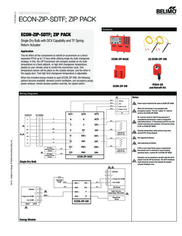
Web Server Manual / Access"Peer-to-peer" connectionEasy access to the device is possible via the link local address. For this, thelaptop must be connected as "peer-to-peer" with the device. The IP addressdoes not need to be known.Ethernet lWebserverNote: The device must be supplied with voltage. If the device is powered via PoE,you can access the device only via the IP address or through the Belimo Assistant App.Establish a direct connection between the PC/laptop and the Belimo device viaan RJ45 cable. You can then access the device via a supported web browser bycalling up the address http://169.254.1.1 or http://belimo.local.The following preconditions must be met:– No static IP address– No alternative IP address set– PC/laptop must be set to "DHCP"Internet Protocol Version 4 (TCP/IPv4) PropertiesInternet Protocol Version 4 (TCP/IPv4) PropertiesGeneralGeneralYou can get IP settings assigned automaticlly if your network supportsthis capabiliy. Otherwise, you need to ask your network administratorfor the appropriate IP settings.GeneralYou can get IP settings assigned automaticlly if your network supportsthis capabiliy. Otherwise, you need to ask your network administratorfor the appropriate IP settings.Obtain an IP address automaticallyObtain an IP address automaticallyIP address:192 . 168 . 0 . 5Subnet mask:255 . 255 . 255 . 0.Obtain DNS server address automaticallyUse the following DNS server addresses:Preferred DNS server:.Alternate DNS server:.Validate settings upon exitAdvanced.OKSubject to technical modificationsCancelAlternate ConfigurationYou can get IP settings assigned automaticlly if your network supportsthis capabiliy. Otherwise, you need to ask your network administratorfor the appropriate IP settings.Obtain an IP address automaticallyUse the following IP address:Use the following IP address:Default gateway:Internet Protocol Version 4 (TCP/IPv4) PropertiesAlternate ConfigurationIP address:192 . 168 . 0 . 2Subnet mask:255 . 255 . 255 . 0Default gateway:.Preferred DNS server:.Alternate DNS server:.Preferred WINS server:.Alternate WINS server:.Use the following IP address:IP address:.Subnet mask:.Default gateway:.Obtain DNS server address automaticallyUse the following DNS server addresses:Validate settings upon exitPreferred DNS server:.Alternate DNS server:.Validate settings upon exitOKCancelAdvanced.OKCancel5
6Web Server Manual / AccessA direct connection must exist in order to access the device via peer-to-peer.This type of connection cannot be used in a network with other consumers.IP addressAs an alternative to the link local address and "peer-to-peer" connection, you canalso access the device using the IP address. This type of connection can also beused in a network with multiple consumers. If there are several devices in thenetwork, valid IP settings have to be assigned to the consumers in advance(IP address and subnet mask).– IP settings for deliveries are as follows:– IP address 192.168.0.10– Subnet mask 255.255.255.0– Open the web browser and enter the following address: http://192.168.0.10, orthe one assigned by the network administratorPlease note that the following conditions are to be observed:Laptop static IP addressLaptop settings DHCPExample: When the device is in delivery condition:x not equal to 10If the device is already connected to a network, matching IP settings must be assigned to the laptop.If the network has a DHCP server and the network adaptersettings on the laptop are set to DHCP, the IP settings will beassigned automatically.Subject to technical modifications
Web Server Manual / AccessUser name and passwordAccess to the device is password-protected.LoginThe connection to this website is not secureUsernamePasswordLoginCancelThere are three standard users with different read and write permissions. Allstandard users and passwords can be seen in the chapter "User administration".Subject to technical modifications7
8Web Server Manual / Startup assistantStartup assistantGeneralThe startup assistant is started after initial entry. The assistant helps to ensurethat the main settings of the device are undertaken right from the start. After thegreeting, it guides you through the following set-up steps:– Cloud– Site information– Application– CommunicationYou can still change all the settings you have entered later.Subject to technical modifications
Web Server Manual / Startup assistantCloudIf you want a connection to the Belimo Cloud, you can enter the data here.Cloud account emailIf you already have a Belimo Cloud account, enter the email address here.Allow automatic updatesThis allows software updates to be automatically installed. After the update, thedevice will reboot automatically and all settings will remain the same.Cloud servicesYou can activate the cloud services such as delta T Optimisation and Supportvia Cloud here. If the cloud services are not activated, you cannot use the following functions: Delta T Optimisation via the Cloud, Online Support and Remote Parametrisation.Site informationSubject to technical modificationsYou can add details about the device here, e.g. mounting location, applicationdetails or the building address. This information is especially important whenmanaging multiple devices. This allows you to identify a device when it is accessed.9
10Web Server Manual / Startup assistantApplicationThis is where you enter the settings for installation, control settings (only forEnergy Valve) and flow values (only for Energy Valve).CommunicationThis is where you adjust all bus-related settings.Subject to technical modifications
Web Server Manual / Startup assistantFinishParametrisation by the startup assistant is now complete. Three notes are displayed:SecurityDirect access to user administration. To ensure secure operation, you need tochange the password for the standard users, and in particular for the adminuser.Advanced settingsDirect access to the application settings. You can also download a commis sioning report here.IT infrastructureDirect access to the IP settings. You can configure the IP settings here accordingto the existing IT infrastructure.Subject to technical modifications11
12Web Server Manual / User InterfaceUser interfaceGeneralAfter completing the commissioning, you will be redirected to the web serveroverview page. This is where you can view all of the data points and access allof the settings.21341 Language settingThis is where you can set the language of the user interface.2 Device nameThe device name entered in the settings is displayed here.3 Navigation menuAllows you to navigate through the different areas to access information andconfigure settings.4 Log OutLogs the current user out of the web server.Language settingThe language used is automatically selected in accordance with thePC settings. If the computer is set to a language that is not available, English willbe selected automatically.You can also select the display language via the drop-down menu.Available nJapaneseKoreanMacedonianNorwegianDutchSubject to technical shSerbianSlovakSlovenianSpanishChinese (Mandarin)
Web Server Manual / User InterfaceOverviewSubject to technical modificationsThis page shows the most important actual values of the device. You get anoverview of the actual values here and can see the status of thedevice.Fault messages can be viewed directly here.13
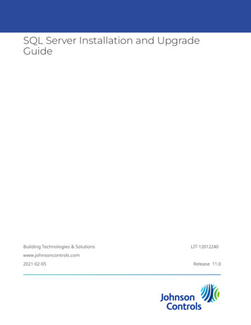
14Web Server Manua / DataDataLive trend and KPIThe visualisation of the system data provides a simple and quick overview ofthe system. The values displayed can be specifically selected.On this page you can view and evaluate the recorded data. Selected data can bevisualised in the live trend view.186243571 Visualisation of the system dataThe saved data from the last 8 days is automatically loaded in this view.2 Zoom outThis function makes it possible to expand the period being viewed.3 AdaptationClicking this button resets the visualisation.4 Arrow navigationThese arrows allow you to navigate along the timeline.5 Load more dataThis function loads all data stored in the product.6 Heat exchanger characteristic curveDisplays the determined characteristic curve of the heat exchanger. This allowsdelta T values to be determined (only for Energy Valve).7 Displayed dataBy selecting or deselecting the check boxes, you can selectively show or hidevalues.8 Zoom functionThe zoom function can be used to limit the period being viewed. Click and dragto zoom in on the selected area.Subject to technical modifications
Web Server Manual / DataThe figure below shows an example of a determined heat exchanger charac teristic curve for the Energy Valve. The orange data points represent the performance curve of the heat exchanger. The green data points represent the corresponding differential temperature curve. The ideal values for the delta T managerare determined.The KPI statistics show the performance of the device since commissioning orduring a specific month. You can select the month via the drop-down menu.The following KPIs are displayed– Control mode– Delta T manager– Flow rate– Power– Delta T– Cooling energy– Heating energy– Total flow– Meter readingSubject to technical modifications15
16Web Server Manual / DataControl mode (only Energy Valve)Shows how many hours the Energy Valve has been operated in total in the different control modes of flow rate, position and power control.Delta T manager (only for Energy Valve)Shows how many hours the delta T manager was active, switched off or instandby mode. The time during which there is no flow requirement is not included in the statistics.FlowShows the maximum, minimum and average flow rate values. The time duringwhich there is no flow requirement is not included in the statistics.PowerShows the maximum, minimum and average power. The time during which there is no flow requirement is not included in the statistics. Delta T: Shows themaximum, minimum and average differential temperature. The time duringwhich there is no flow requirement is not included in the statistics.Cooling energyThe total measured cooling energy is displayed here. If you have selected amonth via the drop-down menu, two values will be displayed. The top value represents the cumulative energy flow between the time of commissioning andthe end of the selected month. The bottom value represents the energy flowduring the selected month.Heating energyThe total measured heating energy is displayed here. If you have selected amonth via the drop-down menu, two values will be displayed. The top value represents the cumulative energy flow between the time of commissioning andthe end of the selected month. The bottom value represents the energy flowduring the selected month.Flow totalThe total measured flow volume is displayed here. If you have selected a monthvia the drop-down menu, two values will be displayed. The top value representsthe cumulative volume flow between the time of commissioning and the end ofthe selected month. The bottom value represents the volume flow during theselected month.Meter readingDisplays the certified meter reading and the service life meter reading. The certified meter reading is the same value that is shown on the display of thedevice. This value is used for accounting purposes. The service life meter read ing starts at the time the device is commissioned and is never reset.Subject to technical modifications
Web Server Manual / DataData loggingSubject to technical modificationsOn this page you can choose to download the data in the short-term memory(31 days uncompressed) or long-term memory (13 months compressed).You can also delete all of the data.17
18Web Server Manual / StatusStatusHealth stateThe current status of the device is displayed here. The fluid, flow rate,power, sensor and actuator parameters are checked.All of the fault messages since commissioning are displayed in the "Chronicle"section. In addition, the time elapsed since the last occurrence of the respectiveerror can be seen.Click on "Show details" to display additional information.Error messagesCategoryError messageProposed solutionFluidGlycol determined– Test the glycol concentrationFreeze warning– Water temperature is low– Test the glycol concentrationReverse flow– Check whether the valve is installed in-line with the direction of flowFlow not reached– Check whether the pump pressure is adequate– Check the pump fittings– Check the flushing bypass– Check the V'max settingFlow rate with closed valve– Check whether the actuator is mounted correctly accord ing to the valve positionFlowThe current flow rate exceeds the nominal – Set the control mode on flow control and V'max to theflow rate. esigned flow ratedPowerPower not realised– Check the supply temperature– Check whether the secondary side is in operation– Check the P'max settingSensorExternal temperature sensor (T1) error– Check the wire connectionIntegrated temperature sensor (T2) error– Check the wire connectionFlow measurement error– Check whether the system is filled with water and that there is no air presentNo communication to the sensor– Check whether the logic module and sensor module aremounted correctly– Restart the device (power off/power on).Actuator cannot move.– Check whether the rotation is 90 .Gear train disengaged– Gear disengagement push-button on the actuator is disengagedNo communication to the actuator– Check the cabling to the actuator– If PoE is used, check whether PoE is activatedActuatorSubject to technical modifications
Web Server Manual / StatusVersion informationYou can view all the version information for your device here.Hardware– Type code– Serial number– Sensor module serial number– Actuator serial number– OC module material number– PlatformSoftware– Operating system version– Basic software version– Communication module firmware version– Active boot slot– Flow sensor firmware versionApplication module– Model name– Model file name– Model versionSubject to technical modifications19
20Web Server Manual / SettingsSettingsApplicationThis is where you can configure all the settings for the application. The settingsare divided into three sections:1231. General settings2. Override3. ParametrisationGeneral settingsCommissioning assistantYou can restart the commissioning assistant here once again to receive assistance for parametrising the device.Commissioning reportAllows for the commissioning report to be viewed and downloaded in PDF format. The commissioning report presents all of the settings and basic data forthe device in a clear and structured way.Settings importClicking on this button takes you to the maintenance menu where you can import a pre-parametrisation in XML format.Settings exportClicking on this button takes you to the maintenance menu where you can export a pre-parametrisation in XML format.Subject to technical modifications
Web Server Manual / SettingsApplication – OverrideNote: The override is reset automaticallyafter 2 hours.OverrideThe override function allows you to override all control signals and force one ofthe following functions:Open: Valve is opened.Close: Valve is closed.Min: The set minimum volumetric flow/position/power (depending on the setcontrol mode) is controlled.Max: The set maximum volumetric flow/position/power (depending on the setcontrol mode) is controlled 1).Nom: The set nominal volumetric flow/position/power (depending on the setcontrol mode) is controlled.Motor stop: The actuator remains at its current position.Relative setpoint: The set relative setpoint for volumetric flow/position/power(depending on the set control mode) is controlled.Relative position: The set relative position, independent of the set control mode,is approached.Simulated operation: Can be used when neither a control signal nor any othersensor data is available, e.g. for presentation purposes.Since V'nom/P'nom can be higher than the maximum required (set) V'max/P'maxof the installation, achieving the nominal values is dependent on the output ofthe pump.1)Subject to technical modifications21
22Web Server Manual / SettingsApplication – ConfigurationUnitsThis is where you can define the displayed units for temperature, flow rate, power and energy.TemperatureFlowPowerEnergy C (*)m /hWJ Fm /skW (*)kWh (*)Kl/min ject to technical modifications Factory preset
Web Server Manual / SettingsApplicationThis is where you can set the fluid and the installation position. For MID-certifieddevices, it is no longer possible to make changes after activation.FluidSelection of the fluid used:– Water– Propylene glycol– Ethylene glycol– Antifrogen L– Antifrogen N– DowCal 200– DowCal 100Glycol overrideThis selection is displayed only if you have selected glycol as the fluid. You canenter the percentage concentration of the glycol here. The glycol display functionis overridden by the input value. Glycol compensation is still carried out with themeasured value.Installation positionThe correct settings are important for allocating the consumed energy as cooling or heating energy:– Valve in supply pipe– Valve in return pipeActuator sync positionThe actuator synchronises its position after the gear disengagement push- button has been pressed. Select "Sync at 0%" to enable synchronisation whenthe valve is closed. Select "Sync at 100%" so that the actuator synchroniseswhen the valve is open.Subject to technical modifications23
24Web Server Manual / SettingsNote:These settings determine the analoguefeedback signal U5.Analogue feedbackYou can select which parameter is output as a feedback signal U5 here.The units correspond to the settings in the "Units" area. The following parameters can be output:– Relative position: Opening angle [ ] valve– Relative flow rate: Current quantity of water– Relative power: Current consumer power output– Supply temperature in the set unit– Return temperature in the set unit– Delta T: Differential temperature, supply and returnDepending on which parameter you select as the output signal, you must definethe maximum and/or minimum value of the output parameter.You can select one of the following signals as the output range:– 0.10 V– 0.5.10 V– 2.10 V– You can manually enter the minimum and maximum voltage of the output signal hereSubject to technical modifications
Web Server Manual / SettingsControl settingsParametrisation of the positioning signal Y.Control modeYou can select the desired control mode here.– Position control: In this setting, the valve operates as a pressure-dependentvalve such as a conventional characterised control valve– Flow control: Operation as a pressure-independent valve similar to an electronic pressure-independent characterised control valve– Power control: The positioning signal directly requests a particular power output at the heat exchanger. The valve operates independently of tempera ture and differential pressureSetpoint sourceYou can select either a bus or an analogue signal as the signal source here.Positioning signal rangeYou can select the operating range of the positioning signal here. The ranges5.10 V, 2.10 V or a user-defined range are available.Signal inversionThe signal can be inverted if desired.Subject to technical modifications25
26Web Server Manual / SettingsMaximum and limitWhen the control mode is set to flow rate or power control, you can configurethe Maximum and Limit settings.V'maxMaximum flow rate as absolute value in the selected unit.V'minMinimum flow rate as absolute value in the selected unit. You can enter a V'minhere to ensure a minimum flow rate with a requirement of 0%. This minimumflow becomes effective at a minimum requirement of the positioning signal.Depending on the analogue setting, this is 0 V, 0.5 V, 2 V or via bus 0%.Note:The definitions of the values V'nom andV'max are provided in the annex to this document.P'maxMaximum power as absolute value in the selected unit. Set this value based onthe design data of the consumer. The value can only be defined if power controlis set as control mode.Delta-T managerActivation or deactivation of the delta T manager. This function can be used toprevent the volumetric flow from increasing when the supply/return tempera ture falls below a set differential temperature. In this case, the valve will not beopened further, even if the positioning signal increases.dT limit function:– Off: Deactivates the delta T manager– On: Activates the delta T manager– On with scaling: Extended delta T limiting is switched onSubject to technical modifications
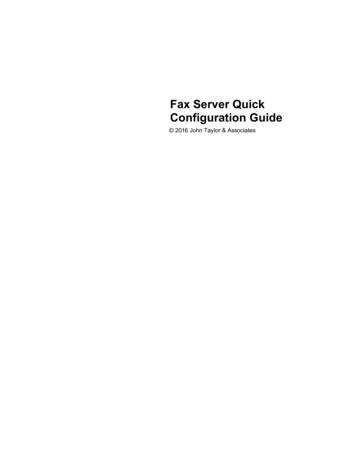
Web Server Manual/SettingsDelta T limit valueNo increase in volumetric flow if this setting value is not reached. In the "On withscaling" mode, this value is dynamic. This value can be read from the heat exchanger characteristic curve determined. (Register KPI and trends – heatexchanger characteristic curve).dT flow rate saturation value: Corresponding flow rate when delta T is reached.Maximum water quantity T WaterPower outputExchangerLimitation TWater quantity [l/min]CAUTION: This does not apply in the "Onwith scaling" mode.Subject to technical modificationsIn operation, the limitation only monitors the differential temperature at a flowvalue 30% of V'max.– In the range below 30% V'max, excessively low differential temperatures arenot corrected by the valve– This operational behaviour ensures that the system restarts properly after astandstill period27
28Web Server Manual / SettingsSite informationYou can enter all of the information about the location of the device here. Thiscan be especially helpful if you are managing multiple devices.Date and timeYou can define these settings in Date and Time.BrowserDate and time of the PC browser connected to the device.DeviceDate and time set on the device.Update device timeClicking on "Update device time" transfers the date and time setting of the connected PC to the device.NTP ServerIf desired, the date and time can be applied from a time server. If multiple devicesare being used, it is also possible to define one device as the time master. To dothis, enter the IP address of the time master for all other devices.Subject to technical modifications
Web Server Manual / SettingsUser administrationYou can create new users via this control panel.Add: Adds a new user.Edit: Edits the user currently selected.Delete: Deletes the user currently selected.Reset: Resets all user settings to the factory settings.There are three standard users included in the factory settings: admin, guestand maintenance.These three users have different read and write permissions. The table belowgives an overview of all the permissions.LegendL Read accessS Write access Page is not displayed.1) Please change the adminpassword during the first start-up.2) Units can be written.Subject to technical modificationsUser g 1)OverviewLLLLive trend and KPIL/SL/SL/SData recordingLLL/SSystem statusLL/SL/SVersion informationLLLApplicationLLLUserLL/SL/SIP setting–LL/SBACnet/MP/ModbusLLL/SCloud setting––L/SDate and time–LL/SMaintenance––L/S2)2)29
30Web Server Manual / SettingsBACnet/MP/ModbusYou can set the selection of the desired communication protocol here. Once aprotocol is selected, you can configure all the relevant settings according to thespecifications of the on-site devices.– BACnet IP– BACnet MS/TP– MP-Bus– Modbus TCP– Modbus RTU– None (only conventional control)IPThis is where you can configure all of the IP settings according to the specifications of the person responsible for the network.Note:The settings do not change for direct access with the laptop.DHCP/ZeroconfWith this setting, the IP address is either automatically assigned to the device ordetermined by the device.– If a DHCP server is present, the device is automatically assigned the IP address by the server– If there is no DHCP server, the device is able to calculate the IP address basedon the Zeroconf specification in the "Zeroconf" settingStatic/ZeroconfThis setting allows the device to be assigned an IP address determined by thenetwork administrator. It is normally used in networks without a DHCP server.Subject to technical modifications
Web Server Manual / SettingsCloudThis is where you can configure all the settings for the Belimo Cloud.Cloud connection statusUses colour to show the connection status of the cloud. If the symbol is green,the connection to the cloud has been established. Red means that no connection could be established.Subject to technical modifications31
32Web Server Manual / SettingsDevice ownerThis is where you can configure the settings for the device owner.Current ownerThis is typically the name of the user who configured the Belimo Cloud settingsand matches the email address provided during the initial installation. Clickingon "Update current owner" retrieves this information again from the Cloud.New ownerUsed when transferring from a current owner (or no owner) to a new owner. Todo this, click on the "Transfer device" button after entering a new owner.Cloud service settingsThis is where you can configure the settings for Updates, Datalog and TaskMode.Datalog and Task ModeEnables data transfer between the device and the Belimo Cloud.– Deactivated: No data transfer– Only Datalog: Only data is stored in the cloud. Settings from the cloud are notadopted by the device– Datalog and Task Flow (Polling): The device checks at intervals whether settings are to be transferred from the cloud– Datalog and Task Fast (PubNub): If settings are changed in the cloud, the device is informed that new settings are to be adopted from the cloud. These arethen automatically adoptedSubject to technical modifications
Web Server Manual / SettingsUpdate modeEnables updating of the software through the Belimo Cloud.– Deactivated: No updates– Device-controlled: Updates are displayed on the web server, no installation– Cloud-controlled, manual: Updates are displayed on the Belimo Cloud, no installation– Cloud-controlled, automatic: Updates are installed automaticallyAdditional informationThis is where you can access a variety of information about the device and subdevices.Connection statusPerforms a routine that helps troubleshoot the connection to the Belimo Cloud.Clicking on "Check connection status" performs the following three steps:– Check of the connection to the next gateway– Check of the connection to the Internet– Check of the connection to the Belimo CloudPubNubShows the connection status to the PubNub service. Green means that the lastconnection attempt was successful. Red means that there is no connection.Subject to technical modifications33
34Web Server Manual / SettingsMaintenanceSettings import/exportThe settings you selected during the commissioning can be saved here as a fileon the computer (export settings).If a large number of devices with the same nominal diameter and the samesettings need to be installed, you can export these settings once and then import and apply them on another valve (browse/import settings).Software updateIt is possible to upload a software update and to execute it directly.Configure encrypted connection to the web serverEnables the SSL certificate to be created in order to establish an HTTPS connection.Other/misc.Restart: When this field is clicked, the device restarts. The previously configuredsettings remain unchanged.Factory reset: You can reset the device back to the factory settings. The stepsare as follows: 1. Press the "Factory settings" field and confirm the message bypressing "OK". 2. Connect the device to the Belimo Assistant App. The device willthen start to reset all of the settings back to the delivery condition. All storeddata will be lost.Subject to technical modifications
Web Server Manual / Belimo Energy Valve annexBelimo Energy Valve annexDefinitionsV'nomV'nom is the maximum possible flow rate through the valve unit. V'nom corresponds to the catalogue value and is the flow rate set at the time of delivery.V'maxV'max is the set maximum flow rate at the highest positioning signal,e.g. 10 V/100%.P'nomP'nom is the maximum controllable power output Q'nom at the heat exchanger.P'maxP'max is the set maximum power output Q
Note: The device must be supplied with voltage. If the device is powered via PoE, . Login. The connection to this website is not secure Username Cancel Password Login. . If you already have a Belimo Cloud account, enter the email address here. Allow automatic updates.