Transcription
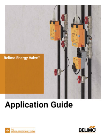
Belimo Energy Valve Application GuideVisitbelimo.com/energy-valve
1GeneralInformationEvolution of Control ValvesThis is the Belimo Energy Valve application guide, a centralsource of materials for the planning, selection, and application ofthe Belimo Energy Valve . It is intended to provide to consultingengineers, system integrators, HVAC contractors,commissioning engineers, facility managers and building ownersworldwide, educational and practical information on this flagshipproduct of Belimo. Belimo Energy Valve is a registeredTrademark of Belimo. For easier reading it is referred in thefollowing text of this guide as Energy Valve or EV.table of contentsIn this guide, you will find information on: T he evolution ofvalve technology The difference betweenpressure dependent andindependent technology Mechanical versuselectronic pressureindependent technology A n overview of the EnergyValve and its features Common applications Best practices includinginstallation andcommissioning tips Supporting tools &resources FAQPART AIntroduction to the Belimo Energy Valve 4PART BBelimo Energy Valve HVAC Applications 60PART CInstallation and Configuration 114This reference guide can be printed on-demand or downloaded. This guide will help increase your knowledge of the BelimoEnergy Valve and its most common applications. However, it does not replace professional engineering work, but serves assupporting document and is your go-to resource for standard questions and solutions. If issues that are more complex arise,please contact your local Belimo sales person or the Belimo support hotline (see www.belimo.com).
part a1Evolution of Control ValvesIntroduction tothe BelimoEnergy Valve overview of key functions and features1 Evolution of Control Valves 62 Pressure Independent Valve Technology 103 What is a Belimo Energy Valve ? 204 Control Modes of the Belimo Energy Valve 305 Feature Overview of the new Belimo Energy Valve 4 50
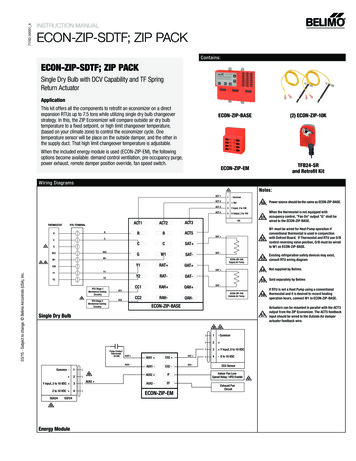
6Belimo Energy Valve – Application GuidePART A Introduction to the Belimo Energy Valve – 1 Evolution of Control Valves11.1 Characterized Control Valve, or CCVFigure 1: CCVFor decades, globe valves dominated the HVAC control valve marketuntil in 1999, Belimo released its Characterized Control Valve or CCV.It was one of the first products to offer accurate reproduction of theequal percentage curve, in particular at low flow rates which were aproblem for other valves. The CCV is also ‘Air bubble tight’ meaning itdoes not permit any water to pass or leak through the valve whenclosed. The CCV continues to be the best-selling control valve on themarket with millions sold worldwide.1.2 Pressure Independent Valve, or PICCVFigure 2: PICCVIn 2003, the first pressure independent valve, or PICCV madeexclusively for the HVAC industry was born. Using the same valvetechnology found in the CCV, a robust mechanical pressure regulatorwas integrated to absorb pressure changes in the system. This allowedthe desired flow to remain constant despite system pressure changes.1.3 Electronic Pressure IndependentValve, or ePIVEvolution ofControl ValvesControl valve technology has significantly evolved over the lasttwo decades. From simple actuation on a valve, to the realm oftruly smart valves. Smart valves do more than simply position,they have various flow and/or temperature sensors installedwithin the valve body and/or in the air or water stream.The combination of valve, actuator and sensors allows the smartvalve to automate many processes that would be difficult or timeconsuming to put into a DDC controller.Figure 3: ePIVAfter four years of development in 2012, Belimo brought the groundbreaking electronic pressure independent valve, or ePIV, to themarket. For the first time, true flow measurement was available on avalve. The ePIV combines an accurate wet calibrated ultrasonic flowmeter with a characterized control valve in one device. This combinationallows for precise control of the flow with the capability to read theactual flow at all times.1.4 Belimo Energy Valve , or EVFigure 4: EVIn 2010 the first version of the Belimo Energy Valve , or EV wasintroduced. In this valve the ePIV was enhanced with temperaturesensors in the supply and return water to measure the DifferentialTemperature (known as delta T) measurement across the coil or heatexchanger. Taking this measurement allows the valve to continuallymonitor, and with built in software even enhance the efficiency of theheat exchange, avoiding costly and inefficient overflow.The Energy Valve opened a new chapter with advanced connectivity.Besides the analogue and bus interfaces, supporting Modbus andBACnet protocols, the EV, also for the first time, included an embeddedweb-server simplifying mechanical and electrical commissioning toseconds. The EV also includes the capability to securely connect to theinternet, the EV had become the industry’s first Internet-of-Things(IoT) control valve.7
8Belimo Energy Valve – Application GuidePART A Introduction to the Belimo Energy Valve – 1 Evolution of Control Valves1.5 Quick Compact Valve, or QCVFigure 5: QCVIn 2013, the Zone Tight QCV, for zone applications was introducedto allow more accurate control of low flows. Combining the Belimo“air bubble tight” ZoneTight ball valve design and an extremelylow power electrical consumption actuator with Quick pop upmounting.1.6 Pressure Independent QuickCompact Valve, or PIQCVFigure 6: PIQCV1.8 Belimo set the new industry standard for innovativevalve, and actuator technology twice.CCV & Zone Valves: In the space of just ten years, Belimohad clearly established with the Characterized Control Valvethe new industry standard for control valves. From 2013,Zone Tight QCV also initiated an exponential growth spurt,with high volumes for zone applications. It is foreseeablethat in the coming decade a large number of outdated shortstroke zone valves will be replaced by energy efficient andair bubble-tight Belimo QCV zone valves.In 2016 the Zone Tight product family became Pressure Independent, the PIQCV combined mechanical pressure independent andZoneTight technology to zone applications.EV 4Certified Metering, eady for Energy-BillingRCharacterized Control Valves1.7 Belimo EV 4, Belimo bringstogether what belongs together.Mechanically Pressure-Independent(based on CCV)EVElectronically Pressure-InpdependenControl Valves ( based on CCV)In 2021, a new range of certified thermal energy meters and theBelimo Energy ValveTM 4 was launched. It offers seamless anddirect integration to the BMS or a 3rd party Building IoT platform,providing valuable data on current operation modes, temperatures,flows or energy consumption which can be directly used fortenant billing.Figure 7: New EV 4PI-Valves: Pressure-independent valves have experiencedexponential growth over the last 5 years. This is driven bycompact, mechanically pressure-independent PIQCV zonevalves, which are replacing the pressure-dependent shortstroke valves that are outdated in many applications.However, the fast market penetration of electonic pressureindependent valves such as the ePIV and EV continues, theywill quickly become the industry standard.Power Controldelta T ManagementePIVTrue FlowControlAll those Belimo Innovations have helped to solve severeproblems and inefficiencies in the hydronic control of HVACsystems, ranging from leaking valves, discomfort from pressurefluctuations, and of course, the low delta T problem.PIQCVPressure-Independent Zone ValvePICCVPressureIndependent Control*CCVPro TipRetrofit of outdated valve and actuator technology isthe first step to energy efficiency. Combining thelatest leak free, pressure independent valves, withmodern efficient variable speed pumps, significantlyreduces power consumption, while increasingoccupant comfort. Consult your local Belimorepresentative for e Control20102020*PICCV product has since been replaced by PIQCV & ePIV productsFor those looking to save energy without sacrificing comfort, the concept of the smart valve has been embraced by themarket. From 2012 to 2021, Belimo has sold several hundred thousand ePIV’s and EVs and both product lines continue to growat very high rates.9
10Belimo Energy Valve – Application Guide2PART A Introduction to the Belimo Energy Valve – 2 Pressure Independent Valve Technology2.1 The traditional approachPressure dependent valvesIn a pressure dependent system, the typical arrangementconsists of a manual balancing valve in series with apressure dependent control valve (globe valve, characterizedcontrol valve, zone valve, etc.). Typically, the balancingvalves have a machined orifice, or venturi, that allows thetechnician to measure differential pressure, known as delta P,to obtain the flow value. The flow is obtained either bycalculating the delta P and the valve’s coefficient (Cv/Kv), orby using flow/delta P tables provided by the valvemanufacturer.Although variable flow systems save building operatorssubstantial pump energy cost every year, complex flowissues caused by pressure fluctuations can arise, resultingin system instabilities. Even the best-designed systems stillmake it challenging to optimize operations, especially duringpart load.Pressure dependent valves can suffer from overflow andunderflow due to mechanical pressure changes in thesystem.Pressure IndependentValve TechnologyThe drive towards greater HVAC efficiency led to variablepumping systems and two-port control valves; requiring controlvalves to operate under dynamic conditions. However, controlvalves remained sized to static design conditions; this madevalve selection, balancing and control problematic. To addressthis, Belimo released the first pressure independent valvedesigned for the HVAC industry.2.2 Pressure independent valvesMaintain the flow independent of pressure fluctuationsSince 2003, when Belimo invented the first PressureIndependent Control Valve, these valves, often referred to asPI Valves, PIV or PICV, have seriously disrupted the way inwhich building HVAC systems are designed, installed andcommissioned, offering savings at virtually every stage of aproject life cycle.For nearly two decades, pressure independent valves havedemonstrated the ability to mitigate costly problemsassociated with pressure dependent systems. Providinghuge improvements in flow consistency irrespective ofsystem pressure fluctuations. PI valves maintain flowthrough each coil, only permitting flow changes whencommanded by the control signal. As a result, heatexchanger performance is unaffected by system pressurefluctuations.Figure 8: PICCV, the first Belimo Pressure Independent Valve11
Belimo Energy Valve – Application GuidePART A Introduction to the Belimo Energy Valve – 2 Pressure Independent Valve Technology2.3 Mechanical PI ValvesThe key componentsHow mechanical PI valves workA mechanical PI valve, sometimes also referred to as a dualvalve, combines a control valve with a differential pressureregulator. The pressure regulator keeps a constant pressureacross the control valve resulting in a known flow for aknown position. As seen in figure 9 the supply pressure canbe measured, at the blue port the outlet pressure. Theseintegrated pressure and temperature ports, referred to as“PT ports”, allow measurements during operation.PI Valves require a minimum differential pressure to operate.This differential pressure is required to load the spring whichpositions the diaphragm. If a hydronic system provides adifferential pressure below this minimum, the pressureregulator mechanism is unable to respond to pressurechanges effectively making the valve pressure dependent,causing it to deliver inconsistent results. If the maximumdifferential pressure rating of the valve is exceeded, thediaphragm will be experiencing additional stress which ifleft for extended periods can damage the regulator. Usually,hydronic systems are designed such that they deliver thedifferential pressure within the required range, with little orno additional equipment or design overhead.PT PortsAdvantages of mechanical PI valves over pressuredependent valvesBy controlling flow and eliminating the effects of pressurefluctuations, pressure independent valves eliminate theneed for extra balancing valves. Incorporating the balancingfunction into the control valve not only minimizes installationcost but also substantially reduces commissioning cost dueto the elimination of the labor-intensive balancing process.PI valves can arrive to the job site pre-set to design flow, sothere is no additional setup required. They can also arriveset to the full flow position to allow higher flushing velocitiesbefore being set to design flow.Occupant comfort, installation simplicity and ongoingflexibility have been the key to the success of the mechanicalPI valve. PI valves are selected on flow and do not requireflow coefficient or valve authority calculations. Changes tothe building’s existing hydronic system doesn’t effect PIvalves avoiding costly re-balancing or comfort issues arisingfrom not re-balancing.Flow ratePressureRegulatorTolerance in %Flow setpoint12Figure 9: Components of a mechanical PI valve, example PIQCVsuesPrrewFloBall ValueFigure 10: Stabilizing pressure and flow changeswith a mechanical PI valve, eg. a PIQCVMinimal delta PDifferential pressureMaximal delta PFigure 11: Improved stability with mechanical PI valvesValue added to the system with PI valvesBuilding owners realize the benefits of PI valves with energysavings and increased occupant comfort. Installers savesignificant amounts of labor by not installing balancing valvesand a reduced commissioning program.In summary, pressure independent valves stabilize thecontrol of variable flow systems, offering greater efficiencyand worry-free, dynamic balancing, making installation andcommissioning a significantly easier task.Challenges with mechanical PI valvesIf you wish to measure the flow through the valve you needan additional device such as a machined orifice or venturi.While many PI valves are equipped with PT ports, theyshould only be used for the measurement of differentialpressure, pressure drop across the PI valve body isn’tsuitable for flow calculations, as its geometry moves withthe regulator as a result of pressure changes. If you intendto verify flow with an external device, careful attentionshould be paid to the combined tolerance of both the valveand the measuring station. For example, if both deviceshave a stated tolerance of /- 10% a reading of anywherebetween 80% & 120% of design should be consideredacceptable.There are several PI valves on the market that attempt toreport a theoretical or calculated flow based on the valveposition. This is often based on the assumption that thedelta P over the valve is within the required range and thatsufficient flow is available. Unfortunately, mechanical PIvalves do not report delta P or the diaphragm position. Forthat reason, it is not advisable to calculate flow based on theposition of the valve alone, as an isolated valve would still bereporting its theoretical flow.13
Belimo Energy Valve – Application GuidePART A Introduction to the Belimo Energy Valve – 2 Pressure Independent Valve TechnologyHow does the ePIV work?2.4 Electronic PI ValvesThe electronic Pressure Independent Valve (ePIV) uses technology very similar tothe universally accepted pressure independent VAV box used in airside applications. By using algorithms incorporated into the smart valve, thecontrol signal DDC is interpreted into a flow requirement, which the valvepositions to provide, delivering distortion free characterized flow.For almost a decade, Belimo Electronic PI valves have enjoyed fast growth asmore and more customers enjoy the peace of mind that they get with thisinnovative product.What are the components of an ePIV?Positioning logic within the electronic valve is key to controlling pressure and flowaccurately. The valve positions itself to be within 1% of the required flow and willremain at that position until the flow value is outside its internal control toleranceof 5%. This prevents continuous movement of the actuator, as minor pressurevariations are typically removed by the system before the valve must correct itsflow by changing position.An electronic PI valve, often referred to as an ePIV, combines a flow meter withpatented glycol compensation, a high resolution actuator and flow control logicinto one device. Flow measurement data from the meter can be collected viaanalogue interfaces or digital communication through Belimo MP-Bus, andoptionally BACnet or Modbus. This provides valuable data to your buildingmanagement system and allows a previously unavailable level of insight into yourhydronic system.Flow rateLike mechanical PI valves, electronic PI valves also require differential pressurewithin a certain range to work. Electronic PI valves are able to maintain pressureindependence at a significantly lower differential pressures, as the ultrasonic flowmeasurement remains accurate down to very low flow rates and they do notrequire pressure to work a regulator.Sensor module with control logicElectronic actuatorTolerance in %Flow setpoint14Minimal delta P, Mechanical PI valveMinimal delta P, Electronic PI valveDifferential pressureMaximal delta PFigure 13: Electronic PI valves can maintain flow at lower delta Pthan mechanical PI valvesPro TipsurePresSupply and returntemperature sensorsFlowControl valve basedon CCV technologyFigure 12: Belimo electronic PI valve example ePIVAlthough electronic PI valves can maintain flow when thedifferential pressure drops below the minimum requirement for PI,any pressure change will result in a large flow rate changeaccentuating valve moments to correct flow deviations.15
Belimo Energy Valve – Application GuidePART A Introduction to the Belimo Energy Valve – 2 Pressure Independent Valve Technology2.5 What advantages do electronic PI valves offer overmechanical PI valves?2.6 Harmonize the pump speed based onelectronic PI valves positionCritical Zone ResetCommissioningHydronic variable flow systems may reset supply water temperature, pump staticpressure, or a combination of both in order to reduce plant energy consumptionand to comply with building codes and standards. The information on the chart infigure 15 illustrates one of the ways in which valve position feedback to theBuilding Automation System BAS may be used to reset the pump pressuresetpoint. In this example, in accordance with ASHRAE 90.1, the index valveposition is used to reset the pump pressure setpoint.Continuous True Flow measurement has removed all theflow verification frustrations associated with mechanical PIvalves, either from an assumed flow using valve position ortrying to read flow from an external device. By reporting thetrue flow rates to the building management system ofchoice, you have not only removed any working from heighttypically associated with waterside commissioning terminalunits, you have made continuous commissioning feasible.The term “Critical Zone Reset” (CZR) is used to describe the BMS’s automateddemand response logic as illustrated in the chart. Under normal operation, thespeed of the pump is controlled by the position of the control valve’s actuators.One of the valves needs to be almost 100% open to satisfy the load – this is thecritical zone. When the critical zone valve starts to close off, that is a sign that thepump speed can be reduced until the valve is almost fully open again. This logicenables a highly energy-efficient operation of a hydronic circuit.Operation TransparencyProduct longevity and reliability should go hand in hand.Control valves, once commissioned, are not often revisitedin a building’s lifetime to ensure their optimum operation.Both pressure dependent and mechanical PI valves can andoften will deviate from design. This can be either due to thedifficulty in adjusting the flow during commissioning, or tonot knowing whether the regulator is working correctly inthe case of mechanical PI valves. An electronic valve willalways report its flow, ensuring your piece of mind over thelifetime of the device. Common issues such as isolated orbypassed units, and even backwards installation of thevalve, can be spotted easily and dealt with before it becomesa bigger issue. A failed valve will become obvious to anoperator and can be alarmed on the BMS, or become analert on your analytics software.Improved Dirt PerformanceThanks to their simplified water path, electronic valves excelin environments where dirt is present. The smallest Belimoelectronic valve will pass a 6mm particle, even if the valve iscontrolling at high delta P, the particle causing a blockage isreported as a lack of flow, which will make the valve simplydrive open until the particle causing the obstruction passesthrough the valve. This effectively eliminates the need forterminal strainers and the additional pressure drop theycreate.Figure 14: Electronic PI valves have a simple flowpath, removing flow direction changes significantlyimproves dirt tolerance.Critical Zone Valve % Open16100When critical zone is wide open; increase pump pressure979491When critical zone is almost wide open;maintain pump pressure88Pro TipIn every closed circuit a centralmethod of removing dirt and air isconsidered best practice. UsingBelimo electronic valves, means thisis the only form of dirt removalrequired. Additional terminal unitstrainers are not required.When critical zone is reasonably less than wide open;decrease pump pressureFigure 15: An example Critical Zone Reset (CZR) strategy.Pro TipUsing the data provided from Energy Valves you can optimize thisprocess, section 5.7 of this guide explains more.17
Belimo Energy Valve – Application GuidePART A Introduction to the Belimo Energy Valve – 2 Pressure Independent Valve TechnologyMore Accurate flow measurementThe Belimo ePIV and the EV position information allows pump pressure reset thatautomatically optimizes pump pressure according to CZR by increasing ordecreasing pump speed or its pressure setpoint. In response, the critical zone’sePIV or Belimo Energy Valve actuator will close the valve to suit the increasedpressure, while maintaining the required flow. In contrast a pressure dependentvalve would remain fully open in effect delivering an overflow to the coil. Amechanical PI valve would also remain fully open, however an internal diaphragmwould move to restrict the flow to design, these unseen diaphragm changesmakes mechanical PI valve positions not suitable for use with CZR.The wet calibrated ultrasonic flow meter, which is an integral part of all ePIVs andEVs, measures more accurately than a typical venturi or orifice plate. It is able toprovide true flow information through transit time technology instead of flowcalculations using differential pressure and flow coefficients. Continuous flow ratefeedback available from the valve allows flow measurements to be displayed ortrended by the BMS.Open 10Feedbackrespondsto loadClosed 2DesignLoad0Figure 16: Pressure Dependent & Mechanical PICV P ResponseOpen 10Valve modulates closed with increase in pump pressure P ResponsePosition Feedback VDCMechanical versus electronic PI; impact based on pump pressureValve remains open until load is less than designPosition Feedback VDC18Feedbackrespondsto PClosed 2Figure 19: Wet calibrated ultrasonic flow meter, partmeasuring stationof the Belimo Energy Valve Any challenges with electronic PI?Due to the method electronic PI valves use to achieve pressure independence,they theoretically take more time to react to large system pressure changes thanmechanical PI valves. Thankfully, large and fast pressure changes are rare, asvariable speed drives and advanced pump control systems will prevent such sharppressure changes from happening. Figure 20 shows how electronic valves react tosignificant pressure changes. The top graph shows the actual flow with the controldead-band overlaid; as pressure increases, the flow moves outside the dead band,and the valve reacts as shown on the lower graph. Later the pressure reduces,causing the flow to move outside the control dead-band again, resulting in anothervalve position correction shown on the lower graph.DesignFlow0Figure 18: MechanicalFigure 17: ePIV or Energy ValvePressure vs. Flow 5%Required flowPro Tip- 5%When planning a Critical zone reset system, you will need a BMSnetwork that is able to quickly communicate with the installedvalves, analyze that data and make control decisions.Valve PositionValve reacts to over flowAdjustment time 90s maxFigure 20: Reaction of ePIV to pressure changesValve reacts t o under flowTime19
20Belimo Energy Valve – Application Guide3PART A Introduction to the Belimo Energy Valve – 3 What is a Belimo Energy Valve ?3.1 Main FeaturesThe Belimo Energy Valve (EV) is a smart pressureindependent control valve for HVAC applications. It is basedon the Belimo Characterized Control Valve (CCV) technologythat has an air bubble tight close off delivering zero leakage.The flow through the valve is permanently measured with anultrasonic flow sensor. The sensor is accurate and it caninclude a patented method of detecting and compensatingfor glycol. The accurate flow information is used toelectronically compensate for any pressure fluctuation inthe system. Combined with the temperature sensors in thesupply and return pipe, it is also used to measure the energysupplied to a coil.The EV has a patented built-in Power Control and BelimoDelta T Manager logic to monitor coil performance andoptimize the heat exchange taking place bymaintaining delta T. In addition to the standardanalog control signal DDC and feedback wiring, theEVcommunicatesitsdatatotheBuildingManagement System (BMS) via Belimo MP-Bus, BACnetor Modbus communication. The built-in web server makesthe EV easy to configure andenables clearvisualization of the valves’ operation in realtime. Performance data is stored for 13 months on theactuator. Optionally, the Belimo Cloud provides lifetimedata.Overview of the main features of the EVIs IoT-readyWhat is a BelimoEnergy Valve ?MeasuresEnergyControlsPowerCompensates Pressure ElectronicallyIncludes Strengths of a CCVFigure 21: Main Features of the EV solutionManagesdelta T21
22Belimo Energy Valve – Application GuidePART A Introduction to the Belimo Energy Valve – 3 What is a Belimo Energy Valve ?3.2 Energy Valve Pillars3.3 Delta T, why its importantCCV StregnthsEfficiency gains – pump savingsCharacterized Control Valve or CCV, accurately reproduces the equal percentagecurve allowing enhanced control at low flows. The CCV is also ‘Air bubble tight’meaning it does not permit any water to pass or leak through the valve whenclosed. The CCV continues to be the best-selling control valve on the market withmillions sold worldwide.While the formula for heat exchange is exact, the reality of the buildings’ operationis far from exact. Our quest for comfort has made modulating control valves andvarying air flows a reality, however this turns optimum heat exchange into amoving target, as ideal air volume and water flow rates are interdependent andnon-linear.Compensates Pressure ElectronicallyThe temperature spread between water entering and leaving a heat exchanger iswhat is commonly referred to as its delta T, this is a measure of how much energythe water has given up as it passed through the heat exchanger. If this is lowerthan expected, less energy is being given up, this is concerning as a significantamount of energy is put into the water, and a further amount of energy expendedmoving that water around the building.Using a flow meter and advanced high-resolution actuator, the Energy Valvepositions to provide the required flow using feedback from a flow meter without atraditional PI cartridge. Energy Valves sense pressure changes as changes inflow, reacting to large pressure changes by moving the valve until the correctflow is achieved, remaining there until either another large pressurechange is experienced, or the required flow is changed.Measure EnergyFlow through the valve is continuously measured using a wet calibrated ultrasonicflow meter; when combined with a matched pair of temperature sensors, the valvemeasures the energy consumed by the heat exchange device.Control PowerNot only can the valve measure energy it can also control it. Power control isa complete departure from traditional valve characteristics; the control signalDDC is interpreted into a power requirement; this makes the valve controlindependent of pressure, water temperatures and air volumes.Manage delta TA key concept of low delta T is the heat exchanger is receiving too much water.The Energy Valve eliminates these overflows by slowing the water down until theheat exchanger gives up the desired amount of energy is a crucial feature of theEnergy Valve.Reducing flow rates to optimize heat exchange has a significant effect at thepumps and the plant; this is why many district energy providers have surchargesfor operators returning low delta T.Figure 22 shows the pump affinity law, this shows us that the relationship betweenpump power consumption and flow is cubed, so a 30% reduction in flow is arounda 50% energy consumption.Figure 22: Pump affinity lawDelta T is an excellent indicator of heat exchange efficiency, the Energy Valveincludes two options for managing delta T, one designed for fixed flow temperaturesand the other for facilities that vary flow temperatures.Low delta T isn’t all about pump savings either; the central plant is compromisedwhen the consumers do not maintain delta T.Digital ReadyCentral plants suffering from low delta T typically lack capacity during peak timesas the water flows too quickly to impart sufficient energy.In addition to the standard analogue control signal DDC and feedbackwiring, the EV can communicate its data to the Building Management System(B
heat exchange, avoiding costly and inefficient overflow. The Energy Valve opened a new chapter with advanced connectivity. Besides the analogue and bus interfaces, supporting Modbus and BACnet protocols, the EV, also for the first time, included an embedded web-server simplifying mechanical and electrical commissioning to seconds.