Transcription
Wiring forDamper Actuators and Control ValvesJuly 2011
Wiring for Damper Actuators and Control ValvesGeneral Wiring InstructionsAlways read the controller manufacturer’s installationliterature carefully before making any connections. Follow allCAUTION: It is good practice to power electronic or digital controllersfrom a separate power transformer than that used for actuators or otherend devices. The power supply design in our actuators and other enddevices use half wave rectification. Some controllers use full waverectification. When these two different types of power supplies areconnected to the same power transformer and the DC commons areconnected together, a short circuit is created across one of the diodes inthe full wave power supply, damaging the controller. Only use a singlepower transformer to power the controller and actuator if you know thecontroller power supply uses half wave rectification.instructions in this literature. If you have any questions, contactthe controller manufacturer and/or Belimo.Multiple actuators, one transformerTransformer(s)Belimo actuators require a 24 VAC Class 2 transformer. Theactuator enclosure cannot be opened in the field, there are noparts or components to be replaced or repaired.– EMC Directive: 2004/108/EC– Software Class A: Mode of Operation Type 1– Low Voltage Directive: 2006/95/ECExample: 3 AF Actuators Supplied, 16 Ga. wire (refer to table onpage 3)350 ft. (allowable wire length) 3 actuators 117 ft. maximum wire runTypical Transformer SizingActuator SeriesEFB, EFXAFB, AFXAFNFB, NFXLFTFGMBAMB / ARBNMBLMB / LRBCMBAHBLHBLUBAMQBNMQBLMQBAHQBLHQBGK / 424242424800-543-9038 USA2Required VAPer ple actuators may be powered from one transformer provided thefollowing rules are followed:1. The TOTAL current draw of the actuators (VA rating) is less than orequal to the rating of the transformer.2. Polarity on the secondary of the transformer is strictly followed.This means that all No. 1 wires from all actuators are connectedto the common leg on the transformer and all No. 2 wires from allactuators are connected to the hotleg. Mixing wire No. 1 & 2 on oneleg of the transformer will result in erratic operation or failure of theactuator and/or controls.Multiple actuators, multiple transformersMultiple actuators positioned by the same control signal may be poweredfrom multiple transformers provided the following rules are followed:1. The transformers are properly sized.2. All No. 1 wires from all actuators are tied together and tied to thenegative leg of the control signal. See wiring diagram.Wire type and wire installation tipsFor most installations, 18 or 16 Ga. cable works well with Belimoactuators. Review job requirements and determine whether a plenumor appliance rated cable is appropriate. Use code-approved wire nuts,terminal strips or solderless connectors where wires are joined. It isgood practice to run control wires unspliced from the actuator to thecontroller. If splices are unavoidable, make sure the splice can bereached for possible maintenance. Tape and/or wire-tie the splice toreduce the possibility of the splice being inadvertently pulled apart.Wire length for actuator installationKeep power wire runs below the lengths listed in the following tables.If more than one actuator is powered from the same wire run, dividethe allowable wire length by the number of actuators to determine themaximum run to any single actuator.866-805-7089 CANADA203-791-8396 LATIN AMERICA / CARIBBEANN40067 - 7/11 - Subject to change. Belimo Aircontrols (USA), Inc.WARNING: The wiring technician must be trained and experiencedwith electronic circuits. Disconnect power supply before attempting anywiring connections or changes. Make all connections in accordancewith wiring diagrams and follow all applicable local and national codes.Provide disconnect and overload protection as required. Use copper,twisted pair, conductors only. If using electrical conduit, the attachmentto the actuator must be made with flexible conduit.
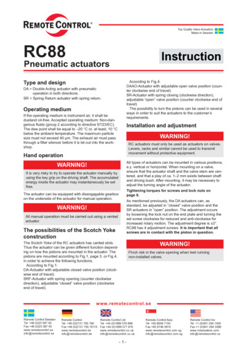
24 VAC110 VAC800-543-9038 USA866-805-7089 CANADA67767GM 105752005001235014345125375163253252208020067.5AM 11509256003752006.5NM 11509256003752007.5AM 11257004503001506.5NM X Distance between Actuator and Supply (feet)9.51150LF US TF US11259001821511NF.UP115080017512018AF 7527550032514575375325345165415110VA7.56MAX Distance between Actuator and Supply (feet)6.51621511GM 1125182658.5LF US TF 036035014VA7NM 5LM/LR 1.5CM 11257004502504.5LM 11257004502504.5LM 700450250150010006003253.5CM 115010006003503.5CM 12001150800MAX Distance between Actuator and Supply (feet)22NKQ GM/GR AM/AR 32511021GK/GKR 2254505TF US1453257LF 4003LU117511257504003LU6003752006AH 7004502505LH 7004502505LU 1400120011001TR 5003002001257018AMQ NMQ LMQ AHQ LHQ *Belimo actuators and auxiliary switches are designed as a IEC protection class II, double insulated, and do not require an independent ground wire toearth, unless otherwise indicated in this document220 VACN40067 - 7/11 - Subject to change. Belimo Aircontrols (USA), Inc.Wire Size vs. Length of Run for Damper Actuators and Control Valves203-791-8396 LATIN AMERICA / CARIBBEAN3
24 VAC110 VAC800-543-9038 USA866-805-7089 087557463238116wire gauge374631515180.55432331487559214416wire 029411923119075893286250367624041488947MAX Distance between Actuator and Supply (feet)0.6AmpsSY45741384622621479916583MAX Distance between Actuator and Supply (feet)1.3AmpsSY42711821077043MAX Distance between Actuator and Supply (feet)1.818wire 12203-791-8396 LATIN AMERICA / CARIBBEANN40067 - 7/11 - Subject to change. Belimo Aircontrols (USA), Inc.The NEC mandates that 24 VAC over 100 VA power requires CLASS 1 wiring conduit. Local codes may vary. Do NOT mix CLASS 1 & CLASS 2 circuits inthe same conduit. Generally, 24 VAC actuators over 100 VA should be changed to 120 VAC models.220 VAC4AmpsWire Size vs. Length of Run for SY Series Actuators
Wiring for Damper Actuators and Control ValvesW236 11On/Off, Spring Return, Electronic Fail-Safe, 24VActuators: EFB24(-S)TF24(-S) USEFX24(-S)GKB24-3AF24(-S) USGKX24-3NFB24(-S)NKQB24-1Hazard IdentificationIndicates a potentially hazardous situation which, if not avoided,may result in minor or moderate injury. It may also be used toalert against unsafe practices.2Equipment damage!Actuators may be connected in parallel. Powerconsumption and input impedance must be observed.WARNINGLive Electrical Components!During installation, testing, servicing and troubleshooting of thisproduct, it may be necessary to work with live electricalcomponents. Have a qualified licensed electrician or otherindividual who has been properly trained in handling live electricalcomponents perform these tasks. Failure to follow all electricalsafety precautions when exposed to live electrical componentscould result in death or serious injury.On/OffLF24(-S) USINSTALLATION NOTESWarnings and Cautions appear at appropriate sections throughoutthis manual. Read these carefully.CAUTIONNFX24(-S)NKQX24-11Provide overload protection and disconnect as required.3Actuators may also be powered by 24 VDC.5Actuators with plenum rated cable do not havenumbers on wires; use color codes instead.AActuators with appliance cables are numbered.APPLICATION NOTESMeets cULus requirements without the need of anelectrical ground connection.On/Off124 VAC Transformer24 VAC Transformer235Blk (1) Common –LineVolts53Red (2) Blk (1) CommonLineVoltsN40067 - 7/11 - Subject to change. Belimo Aircontrols (USA), Inc.aa opena closedRed (2) HotWht (3) The indication of directionis valid for switch position 1.10NKQOn/Off124 VAC TransformerLineVolts35Blk (1) Common –aRed (2) HotWht (3) Y1 inputGKRefer to page 26 for auxiliary switch (-S models) wiring.800-543-9038 USA866-805-7089 CANADA203-791-8396 LATIN AMERICA / CARIBBEAN5
Wiring for Damper Actuators and Control ValvesW231 A 11On/Off, Spring Return, 120, 230V and UPActuators: UP(-S)AF120(-S) US/AF230(-S) USLF120(-S) US/LF230(-S) USTF120(-S) USHazard IdentificationINSTALLATION NOTESWarnings and Cautions appear at appropriate sections throughoutthis manual. Read these carefully.CAUTION14Indicates a potentially hazardous situation which, if not avoided,may result in minor or moderate injury. It may also be used toalert against unsafe practices.2Equipment damage!Actuators may be connected in parallel. Powerconsumption and input impedance must be observed.TF120(-S) US can be supplied with both 120 VACand 230 VAC.19UP models and TF120(-S) US uses “L” instead of “H”on #2 wire.20All 120 VAC, 230 VAC and UP actuators use appliance ratedcables.UPUniversal Power Supply (UP) models can be suppliedwith 24 VAC up to 240 VAC.WARNINGLive Electrical Components!During installation, testing, servicing and troubleshooting of thisproduct, it may be necessary to work with live electricalcomponents. Have a qualified licensed electrician or otherindividual who has been properly trained in handling live electricalcomponents perform these tasks. Failure to follow all electricalsafety precautions when exposed to live electrical componentscould result in death or serious injury.APPLICATION NOTESMeets cULus requirements without the need of anelectrical ground connection.On/OffLineVolts14UP22019Wht NWht (1) NeutralBlk HBlkN40067 - 7/11 - Subject to change. Belimo Aircontrols (USA), Inc.120 VAC230 VAC(2) HotRefer to page 26 for auxiliary switch (-S models) wiring.800-543-9038 USA6866-805-7089 CANADA203-791-8396 LATIN AMERICA / CARIBBEAN
Wiring for Damper Actuators and Control ValvesW232 11Floating Point, Spring Return, 24VActuators:LF24-3(-S) USTF24-3(-S) USLFC24-3.USHazard IdentificationWarnings and Cautions appear at appropriate sections throughoutthis manual. Read these carefully.INSTALLATION NOTESEquipment damage!Actuators may be connected in parallel. Powerconsumption and input impedance must be observed.Actuators with plenum rated cable do not have numbers onwires; use color codes instead. Actuators with appliancecables are numbered.Actuators Hot wire must be connected to the control boardcommon.For triac sink the Common connection from the actuatormust be connected to the Hot connection of the controller.The actuator must be connected to the control board common.5Indicates a potentially hazardous situation which, if not avoided,may result in minor or moderate injury. It may also be used toalert against unsafe practices.2Actuators may also be powered by 24 VDC.3CAUTION611WARNINGLive Electrical Components!During installation, testing, servicing and troubleshooting of thisproduct, it may be necessary to work with live electricalcomponents. Have a qualified licensed electrician or otherindividual who has been properly trained in handling live electricalcomponents perform these tasks. Failure to follow all electricalsafety precautions when exposed to live electrical componentscould result in death or serious injury.APPLICATION NOTESMeets cULus requirements without the need of anelectrical ground connection.† ActuatorWire Number4545TF24-3 USTF24-3-S USLF24-3 USLF24-3-S USFloating PointColorOrgOrgGrnWhtTriac Source24 VAC Transformer324 VAC TransformerBlk (1) CommonLineVoltsN40067 - 7/11 - Subject to change. Belimo Aircontrols (USA), Inc.5LineVoltsRed (2) HotabWht (3) †2Hot Com5Blk (1) CommonRed (2) HotCWCCWWht (3) LF24-3(-S) USLFC24-3-R USLFC24-3-S USTF24-3(-S) USThe indication of directionis valid for switch position CW.† CWCCWLF24-3(-S) USTF24-3(-S) USThe indication of directionis valid for switch position CW.ControllerTriac SinkTriac Sink with Separate Transformer24 VAC TransformerLineVolts2HotCom51124 VAC TransformerBlk (1) CommonRed (2) Hot24 VAC Transformer6LineVoltsWht (3) †CWLineVolts25 CCWBlk (1) CommonHotLF24-3(-S) USTF24-3(-S) USComRed (2) Hot6Wht (3) ControllerThe indication of directionis valid for switch position CW.†CW CCWLF24-3(-S) USTF24-3(-S) USControllerThe indication of directionis valid for switch position CW.Refer to page 26 for auxiliary switch (-S models) wiring.800-543-9038 USA866-805-7089 CANADA203-791-8396 LATIN AMERICA / CARIBBEAN7
Wiring for Damper Actuators and Control ValvesActuators: LMB24-3(-S) (-P5) (-P10) (-T)TR24-3(-T) USCMB24-3 NMB24-3ARB24-3-5AMB24-3(-S)GMB24-3 GRB24-3-5LMX24-3(-T)NMX24-3(-T)GRB24-3-7Hazard IdentificationIndicates a potentially hazardous situation which, if not avoided,may result in minor or moderate injury. It may also be used toalert against unsafe practices.2Equipment damage!Actuators may be connected in parallel. Powerconsumption and input impedance must be observed.LRB24-3(-S) ARX24-3ARB24-3(-S) LRX24-3LRCB24-3(-S)INSTALLATION NOTESWarnings and Cautions appear at appropriate sections throughoutthis manual. Read these carefully.CAUTIONAMX24-3(-T)GMX24-3 GMB24-3-X13Actuators may also be powered by 24 VDC.5Actuators with plenum rated cable do not havenumbers on wires; use color codes instead.Actuators with appliance cables are numbered.16The TR24-3-T US actuators are provided witha numbered screw terminal strip instead of cable.17TR24-3 US actuators cannot be wired in parallel.WARNINGLive Electrical Components!During installation, testing, servicing and troubleshooting of thisproduct, it may be necessary to work with live electricalcomponents. Have a qualified licensed electrician or otherindividual who has been properly trained in handling live electricalcomponents perform these tasks. Failure to follow all electricalsafety precautions when exposed to live electrical componentscould result in death or serious injury.APPLICATION NOTESMeets cULus requirements without the need of anelectrical ground connection.Floating PointOn/Off24 VAC Transformer23524 VAC TransformerBlk (1) CommonLineVolts35Blk (1) CommonLineVoltsRed (2) 2Red (2) aa opena closedWht (3) 1 0The indication of directionis valid for switch position 1.Wht (3) 3.LRB(X)24-3.ARB(X)24-3.LineVoltsThe indication of directionis valid for switch position 1.GMB(X)24-3.CMB24-3.LRB(X)24-3.ARB(X)24-3.1617524 VAC TransformerBlk 1 Common51617Blk 1 CommonLineVoltsRed 2 Red 2 Wht 3 Note: TR24-3 (-T) US cannotbe wired in parallel withany actuator.LMB(X)24-3.NMB(X)24-3.AMB(X)24-3.Floating PointOn/Off – SPDT Switch24 VAC Transformer1 0Wht 3 Note: TR24-3 (-T) US cannotbe wired in parallel withany actuator.TR24-3 (-T) USTR24-3 (-T) USRefer to page 26 for auxiliary switch (-S models) and -P5, -P10 potentiometer wiring.800-543-9038 USA8866-805-7089 CANADA203-791-8396 LATIN AMERICA / CARIBBEANN40067 - 7/11 - Subject to change. Belimo Aircontrols (USA), Inc.W332 11On/Off and Floating Point, Non-Spring Return, 24V
Wiring for Damper Actuators and Control ValvesW612 11Floating Point, Electronic Fail-Safe, 24VActuators: GKB24-3Hazard IdentificationINSTALLATION NOTESWarnings and Cautions appear at appropriate sections throughoutthis manual. Read these carefully.CAUTIONIndicates a potentially hazardous situation which, if not avoided,may result in minor or moderate injury. It may also be used toalert against unsafe practices.2Equipment damage!Actuators may be connected in parallel. Powerconsumption and input impedance must be observed.WARNINGLive Electrical Components!During installation, testing, servicing and troubleshooting of thisproduct, it may be necessary to work with live electricalcomponents. Have a qualified licensed electrician or otherindividual who has been properly trained in handling live electricalcomponents perform these tasks. Failure to follow all electricalsafety precautions when exposed to live electrical componentscould result in death or serious injury.1Provide overload protection and disconnect as required.3Actuators may also be powered by 24 VDC.5Control signal may be pulsed from either the Hot (source)or the Common (sink) 24 VAC line.8Contact closures A & B also can be triacs.A & B should both be closed for triac source and open fortriac sink.9For triac sink the common connection from the actuatormust be connected to the hot connection of the controller.APPLICATION NOTESMeets cULus requirements without the need of anelectrical ground connection.N40067 - 7/11 - Subject to change. Belimo Aircontrols (USA), Inc.Floating PointGKB24-3800-543-9038 USA866-805-7089 CANADA203-791-8396 LATIN AMERICA / CARIBBEAN9
Wiring for Damper Actuators and Control X120-3ARX120-3CMB120-3Hazard IdentificationINSTALLATION NOTESWarnings and Cautions appear at appropriate sections throughoutthis manual. Read these carefully.CAUTIONIndicates a potentially hazardous situation which, if not avoided,may result in minor or moderate injury. It may also be used toalert against unsafe practices.2Equipment damage!Actuators may be connected in parallel. Powerconsumption and input impedance must be observed.15LMB(X), NMB(X), AMB(X), GMB(X), LRB(X), and ARB(X)can be supplied with either 120 VAC or 230 VAC.19All 120VAC and 230VAC actuators use appliance ratedcables.AActuators with appliance cables are numbered.WARNINGLive Electrical Components!During installation, testing, servicing and troubleshooting of thisproduct, it may be necessary to work with live electricalcomponents. Have a qualified licensed electrician or otherindividual who has been properly trained in handling live electricalcomponents perform these tasks. Failure to follow all electricalsafety precautions when exposed to live electrical componentscould result in death or serious injury.APPLICATION NOTESMeets cULus requirements without the need of anelectrical ground connection.Floating PointOn/Off100 to 240 VAC21519100 to 240 VAC15219N L1Blu (1) Common –N L1Blk (1) CommonH L2Blk (2) H L2Red (2) a opena closedaThe indication of directionis valid for switch position 1.Wht (3) 10Wht (3) The indication of directionis valid for switch position 1.10Refer to page 26 for auxiliary switch (-S models) wiring.800-543-9038 USA10866-805-7089 CANADA203-791-8396 LATIN AMERICA / CARIBBEANN40067 - 7/11 - Subject to change. Belimo Aircontrols (USA), Inc.W364 11On/Off and Floating Point, Non-Spring Return, 100 to 240V
Wiring for Damper Actuators and Control ValvesW233 A 11Proportional, Spring Return, FX24-SR(-S)AFB24-SR(-S)AFX24-SR(-S)AF24-SR USLF24-SR(-S) USTF24-SR(-S) USAFA24-SR USHazard IdentificationINSTALLATION NOTESWarnings and Cautions appear at appropriate sections throughoutthis manual. Read these carefully.CAUTIONIndicates a potentially hazardous situation which, if not avoided,may result in minor or moderate injury. It may also be used toalert against unsafe practices.4Equipment damage!Up to four actuators may be connected in parallel if notmechanically linked. Power consumption and inputimpedance must be observed.WARNINGLive Electrical Components!During installation, testing, servicing and troubleshooting of thisproduct, it may be necessary to work with live electricalcomponents. Have a qualified licensed electrician or otherindividual who has been properly trained in handling live electricalcomponents perform these tasks. Failure to follow all electricalsafety precautions when exposed to live electrical componentscould result in death or serious injury.3Actuators may also be powered by 24 VDC.5Actuators with plenum rated cable do not havenumbers on wires; use color codes instead.Actuators with appliance cables are numbered.6Only connect common to neg. (–) leg of control circuits.APPLICATION NOTESMeets cULus requirements without the need of anelectrical ground connection.7A 500 Ω resistor converts the 4 to 20 mA controlsignal to 2 to 10 VDC.8The AFA24-SR US and TF24-SR(-S) US are suppliedwithout position feedback.† Actuator24 VAC TransformerLine47Blk (1) CommonVoltsN40067 - 7/11 - Subject to change. Belimo Aircontrols (USA), Inc.3Red (2) Hot(–)Control Signal( )VDC/mAΩ500 Ω2 to 10 VDC (–)Feedback Signal ( )5Wht (3) Y Input,2 to 10†Wire )AFX24-SR(-S)AF24-SR USNFB24-SR(-S)NFX24-SR(-S)LF24-SR USLF24-SR-S USColorOrgOrgOrgOrgWhtOrgOrgGrnWht(5) U Output,2 to -SR(-S)AF24-SR USNFB24-SR(-S)NFX24-SR(-S)LF24-SR(-S) US24 VAC TransformerLine347Blk (1) CommonVolts(–)Control Signal( )VDC/mA6Ω500 ΩRed (2) Hot5Wht (3) Y Input,2 to 10V8AFA24-SR USTF24-SR(-S) USRefer to page 26 for auxiliary switch (-S models) wiring.800-543-9038 USA866-805-7089 CANADA203-791-8396 LATIN AMERICA / CARIBBEAN11
Wiring for Damper Actuators and Control ValvesW333 11Proportional, Non-Spring Return, Electronic Fail-Safe, 24VActuators: LMB24-SR (-T)NMB24-SRLMX24-SR (-T)GMB24-SRAMX24-SR (-T)CMB24-SR-R GKB24-SRAMB24-SRCMB24-SR-LNMX24-SR (-T)GMX24-SRGKX24-SRHazard IdentificationINSTALLATION NOTESWarnings and Cautions appear at appropriate sections throughoutthis manual. Read these carefully.3Actuators may also be powered by 24 VDC.5Actuators with plenum rated cable do not havenumbers on wires; use color codes instead.Actuators with appliance cables are numbered.6Only connect common to neg. (–) leg of control circuits.Terminal models (-T) have no-feedback.CAUTIONIndicates a potentially hazardous situation which, if not avoided,may result in minor or moderate injury. It may also be used toalert against unsafe practices.4LRB24-SR TR24-SR (-T) USARB24-SR LRX24-SRARX24-SRNKQB24-SR NKQX24-SREquipment damage!Up to four actuators may be connected in parallel if notmechanically linked. Power consumption and inputimpedance must be observed.APPLICATION NOTESWARNINGLive Electrical Components!During installation, testing, servicing and troubleshooting of thisproduct, it may be necessary to work with live electricalcomponents. Have a qualified licensed electrician or otherindividual who has been properly trained in handling live electricalcomponents perform these tasks. Failure to follow all electricalsafety precautions when exposed to live electrical componentscould result in death or serious injury.BlkLine7Ω(–)500 ΩControl Signal( )VDC/mA7324 VAC Transformer4Line(1) Common5(–)Control Signal( )VDC/mAWht (3) Y Input 2 to 10VΩ500 ΩRed (2) Hot5Wht (3)Y Input, 2 to 10VOrg (5)U Output, 2 to 10V72 to 10 VDC (–)Feedback Signal ( )64Blk (1) CommonVoltsRed (2) HotVoltsA 500 Ω resistor converts the 4 to 20 mA controlsignal to 2 to 10 VDC.TR24-SR (-T) US61 (X)24-SRCMB24-SR.GK.NK.800-543-9038 USA12866-805-7089 CANADA203-791-8396 LATIN AMERICA / CARIBBEANN40067 - 7/11 - Subject to change. Belimo Aircontrols (USA), Inc.324 VAC TransformerMeets cULus requirements without the need of anelectrical ground connection.
Wiring for Damper Actuators and Control ValvesW365 11Proportional, Non-Spring Return, 100 to 240VActuators: d IdentificationINSTALLATION NOTESWarnings and Cautions appear at appropriate sections throughoutthis manual. Read these carefully.CAUTION15LMB(X), NMB(X), AMB(X), GMB(X), LRB(X), andARB(X) can be supplied with either 120 VAC or 230 VAC.6Only connect common to neg. (–) leg of control circuits.19All 120 VAC and 230 VAC actuators use appliance ratedcables.AActuators with appliance cables are numbered.Indicates a potentially hazardous situation which, if not avoided,may result in minor or moderate injury. It may also be used toalert against unsafe practices.2Equipment damage!Actuators may be connected in parallel. Powerconsumption and input impedance must be observed.WARNINGLive Electrical Components!During installation, testing, servicing and troubleshooting of thisproduct, it may be necessary to work with live electricalcomponents. Have a qualified licensed electrician or otherindividual who has been properly trained in handling live electricalcomponents perform these tasks. Failure to follow all electricalsafety precautions when exposed to live electrical componentscould result in death or serious injury.2A 500 Ω resistor converts the 4 to 20 mA controlsignal to 2 to 10 VDC.19N L1Wht (1) NeutralH L2Blk (2) Hot 67Cable 215Meets cULus requirements without the need of anelectrical ground connection.Blk (1) Common7(–)Control SignalVDC/mA ( )2 to 10 VDC (–)Feedback Signal ( )Red (2) Hot 5Wht (3) Y Input, 2 to 10VOrg (5) U Output, 2 to 10V1800-543-9038 USACable 1N40067 - 7/11 - Subject to change. Belimo Aircontrols (USA), Inc.100 to 240 VACAPPLICATION NOTES0866-805-7089 CANADA203-791-8396 LATIN AMERICA / CARIBBEAN13
Wiring for Damper Actuators and Control ValvesW225 2 11Phasecut Control Signal, Spring Return and Non-Spring Return, 24VActuators:AF24-PC Hazard IdentificationINSTALLATION NOTESWarnings and Cautions appear at appropriate sections throughoutthis manual. Read these carefully.3Actuators may also be powered by 24 VDC.5Actuators with plenum rated cable do not havenumbers on wires; use color codes instead.Actuators with appliance cables are numbered.CAUTIONIndicates a potentially hazardous situation which, if not avoided,may result in minor or moderate injury. It may also be used toalert against unsafe practices.2Equipment damage!Actuators may be connected in parallel. Powerconsumption and input impedance must be observed.APPLICATION NOTESWARNINGLive Electrical Components!During installation, testing, servicing and troubleshooting of thisproduct, it may be necessary to work with live electricalcomponents. Have a qualified licensed electrician or otherindividual who has been properly trained in handling live electricalcomponents perform these tasks. Failure to follow all electricalsafety precautions when exposed to live electrical componentscould result in death or serious injury.2Meets cULus requirements without the need of anelectrical ground connection.5324 VAC TransformerN40067 - 7/11 - Subject to change. Belimo Aircontrols (USA), Inc.Blk (1) Common –LineVoltsRed (2) Hot Wht *(3) Y Input, 0 to 10V phasecut(–)Control Signal( )0 to 10 V PhasecutOrg‡ (5) U Output, 2 to 10V PC* White color wire for AF24-PC US, Pink color for all others.‡ White color wire for AF24-PC US, Orange color for all others.800-543-9038 USA14866-805-7089 CANADA203-791-8396 LATIN AMERICA / CARIBBEAN
Wiring for Damper Actuators and Control ValvesW604 11Proportional, Spring Return, 24V, 3 kΩ or 10 kΩ Control InputActuators: LF24-ECON-R03 USLF24-ECON-R10 USAF24-ECON-R03 USHazard IdentificationINSTALLATION NOTESWarnings and Cautions appear at appropriate sections throughoutthis manual. Read these carefully.Indicates a potentially hazardous situation which, if not avoided,may result in minor or moderate injury. It may also be used toalert against unsafe practices.2Equipment damage!Actuators may be connected in parallel. Power consumptionand input impedance must be observed.Override Control27A relay or switch can spring return the actuator when theRTU fan de-energizes, or if low ambient temperature is sensed.A standard relay can be used to close the sensor circuit toengage economizer mode, e.g. outside air changeover devicelike a dry bulb or enthalpy limit switch. Honeywell logicmodule W7459A and enthalpy sensor C7400 also provideterminals for this switching.29A remote CO2 sensor or DDC controller can change thestandard relay opening or closing the sensor circuit. Thisdevice can be a relay or a dry bulb/enthalpy limit switch.30Override control for Y2 only accepts 0 to 10 VDCoverride control.ApplicationDrive closed (0%)Morning warm-up cycle24 VACW203AF24-ECONLF24-ECON positionY1CommonDrive open (100%)Smoke PurgeY1Open wireDrive to min. positionMechanical cooling inuse, RTU thermostatcalls for heat.0 VDC to 10 VDCMin. position of 0% to 100%BLineVoltsBlk (1) CommonRed (2) Hot27Wht (3) Y1AOverride potentiometervia a remote C02sensor/controller orDDC controller.Standard Economizer Mode Wiring2524 VAC TransformerOrg (4) Y2 Min-pos, 0 to 10VGrn (5) U Output, 2 to 10VDefaultCWCCWAOverrideClosed (0%)BOverrideOpen (100%)(–)Control Signal( )0 to 10 VDC29301026.8.2.4.6MINAF24-ECON-R03 USLF24-ECON-R03 USLF24-ECON-R10 USW202N40067 - 7/11 - Subject to change. Belimo Aircontrols (USA), Inc.Min-position is adjustable from 0 to 100% with apotentiometer on the actuator cover.OverrideWire Input SignalY22628WARNINGLive Electrical Components!During installation, testing, servicing and troubleshooting of thisproduct, it may be necessary to work with live electricalcomponents. Have a qualified licensed electrician or otherindividual who has been properly trained in handling live electricalcomponents perform these tasks. Failure to follow all electricalsafety precautions when exposed to live electrical componentscould r
Wiring for Damper Actuators and Control Valves On/Off, Spring Return, Electronic Fail-Safe, 24V Blk (1) Common Red (2) Hot 24 VAC Transformer Line Volts 2 3 5 Actuators with plenum rated cable do not have numbers on wires; use color codes instead. Actuators with appliance cables are numbered. 3 Actuators may also be powered by 24 VDC. 5