Transcription
Design No. P522May 05, 2020Unrestrained Assembly Rating — 1 HrFinish Rating — 25 Min (See Items 3 or 3A )This design was evaluated using a load design method other than the Limit States DesignMethod (e.g., Working Stress Design Method). For jurisdictions employing the Limit StatesDesign Method, such as Canada, a load restriction factor shall be used — SeeGuide BXUV or BXUV7* Indicates such products shall bear the UL or cUL Certification Mark for jurisdictionsemploying the UL or cUL Certification (such as Canada), respectively.
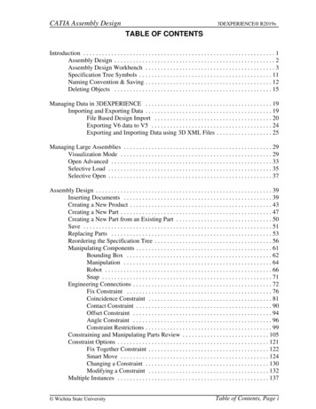
1. Roofing System* — Any UL Class A, B or C Roofing System (TGFU) or Prepared Roof Covering (TFWZ) acceptablefor use over nom 15/32 in. thick wood structural panels, min. grade "C-D" or "Sheathing". Nom 15/32 in. thick woodstructural panels secured to trusses with No. 6d ringed shank nails spaced 12 in. OC along each truss. Staples havingequal or greater withdrawal and lateral resistance strength may be substituted for the 6d nails. Construction adhesivemay be used with either the nails or staples.2. Trusses — Pitched or parallel chord wood trusses, spaced a max of 24 in. OC, fabricated from nom 2 by 4 lumber,with lumber oriented vertically or horizontally. Truss members secured together with min. 0.0356 in. thick galv steelplates. Plates have 5/16 in. long teeth projecting perpendicular to the plane of the plate. The teeth are in pairs facingeach other (made by the same punch), forming a split tooth type plate. Each tooth has a chisel point on its outsideedge. These points are diagonally opposite each other for each pair. The top half of each tooth has a twist for stiffness.The pairs are repeated on approximately 7/8 in. centers with four rows of teeth per inch of plate width. Where thetruss intersects with the interior face of the exterior walls, the min truss depth shall be 5-1/4 in. with a min roof slopeof 3/12 and a min. area in the plane of the truss of 21 sq/ft. Where the truss intersects with the interior face of theexterior walls, the min truss depth may be reduced to 3 in. if the batts and blankets ( Item 3) are used as shown in theabove illustration (Alternate Insulation Placement) and are firmly packed against the intersection of the bottom chordsand the plywood sheathing.3. Batts and Blankets* — (Optional) — Required when Item 6B is used — Glass fiber insulation, secured to the woodstructural panels with staples spaced 12 in. OC or to the trusses with 0.090 in. diam galv steel wires spaced 12 in. OC.Any glass fiber insulation bearing the UL Classification Marking as to Surface Burning Characteristics and/or FireResistance, having a min density of 0.5 pcf. As an option, the insulation may be fitted in the concealed space, drapedover the resilient channel/gypsum board ceiling membrane when resilient channels and gypsum board attachment ismodified as specified in Items 6 and 7. When Steel Framing Members (Item 6B) are used, max 3-1/2 in. thickinsulation shall be draped over the furring channels (Item 6Ba) and gypsum board ceiling membrane, and frictionfitted between trusses and Steel Framing Members (Item 6Bd). The finished rating has only been determined when theinsulation is secured to the decking.3A. Fiber, Sprayed* — As an alternate to Item 3 (not evaluated for use with Item 6B) — Any thickness of sprayapplied cellulose insulation material, having a min density of 0.5 lb/ft3, applied with water, over the resilientchannel/gypsum board ceiling membrane when resilient channels and gypsum board attachment is modified asspecified in Items 6 and 7. Fiber, Sprayed is applied with moisture in accordance with the application instructionssupplied with the product. The finish rating when Fiber Sprayed is used has not been determined. Alternateapplication method: The fiber is applied without water or adhesive in accordance with the application instructionssupplied with a minimum density of 0.5 lb/ft3 over the resilient channel/gypsum board ceiling membrane whenresilient channels and gypsum board attachment is modified as specified in Items 6 and 7. Alternate applicationmethod: The fiber is applied without water or adhesive to a nominal density of 3.5 lb/ft3 behind netting (Item 9)stapled to the rafters. The netting is stapled at both lower edges of the rafters creating a cavity to accept the cellulosefiber.
U S GREENFIBER L L C — INS735, INS745, INS750LD, and SANCTUARY for use with wet or dry application. INS510LD,INS515LD, INS541LD, INS735, INS765LD, and INS773LD are to be used for dry application only.3B. Foamed Plastic* — (As an alternate to Item 3 or 3A, Not Shown) — Spray foam insulation applied directly to theunderside of the underside of the roofing system (Item 1). Spray foam insulation installed to a maximum thickness of10 in. at a nominal 0.5 lb/ft3 density, while maintaining a minimum 8-1/2 in. clearance between the spray foaminsulation and the gypsum board (Item 7). When spray foam insulation is used, resilient channels (Item 6) shall beinstalled maximum 12 in. OC, with channels adjacent to butt joints of gypsum board (Item 7) installed at 6 in. OC toallow for maximum 3 in. spacing off ends of the gypsum board joints. Gypsum board (Item 7) to be installed using 11/4 in. long Type S screws, spaced maximum 8 in. OC, and butted end joints shall be staggered min. 2 ft within theassembly, and occur midway between the continuous furring channels. If used with a fire damper (Items 5 through 5K)in the concealed space, minimum 1 in. clearance to be maintained between damper housing and spray foaminsulation. Not evaluated for use with Items 6A through 6F.SES FOAM INC — Sucraseal3C. Cavity Insulation - Batts and Blankets* or Fiber, Sprayed* — (As described above) in Items 3 and 3A — (ForUse with Item 7B, Not Shown) — Min. 3-1/2 in thick with no limit on maximum thickness fitted in the concealed space,draped over the resilient channel (Item 6G)/gypsum board (Item 7B) ceiling membrane.3D. Foamed Plastic* — (As alternate to Item 3, 3A, or 3B, Not Shown) — Spray foam insulation applied directly to theunderside of the roofing system (Item 1). Spray foam insulation installed to a maximum thickness of 10 in. at anominal 0.5 lb/ft3 or 2.0 lb/ft3 density, depending on the product installed. When spray foam insulation is installed,resilient channels (Item 6) shall be installed maximum 12 in. OC, with channels adjacent to butt joints of gypsum board(Item 7) spaced maximum 3 in. away from gypsum butt joints. Gypsum board (Item 7) to be installed using minimum1-1/4 in. long Type S screws, spaced maximum 8 in. OC, and butted end joints shall be staggered min. 2 ft within theassembly, and occur midway between the continuous furring channels. If used with a fire damper (Items 5 through 5H)in the concealed space, minimum 1 in. clearance to be maintained between damper housing and spray foaminsulation. Not evaluated for use with Items 6A through 6F.BASF CORP — Enertite NM, Enertite G, FE178 , Spraytite 178, Spraytite 81206, Walltite 200, Walltite US,Walltite US-N, and Walltite HP 3E. Foamed Plastic* — (As an alternate to Item 3, 3A, 3B, 3C, or 3D, Not Shown) — Spray foam insulation applieddirectly to the underside of the underside of the roofing system (Item 1). Spray foam insulation installed to amaximum thickness of 17 in. at a nominal 0.5 lb/ft3 density, while maintaining a minimum 1-1/2 in. clearance betweenthe spray foam insulation and the gypsum board (Item 7). When spray foam insulation is used, resilient channels (Item6) shall be installed maximum 12 in. OC, with channels adjacent to butt joints of gypsum board (Item 7) installed at 6in. OC to allow for maximum 3 in. spacing off ends of the gypsum board joints. Gypsum board (Item 7) to be installedusing 1-1/4 in. long Type S screws, spaced maximum 8 in. OC, and butted end joints shall be staggered min. 2 ft withinthe assembly, and occur midway between the continuous furring channels. If used with a fire damper (Items 5 through5K) in the concealed space, no clearance is necessary between damper housing and spray foam insulation. Notevaluated for use with Items 6A through 6F.SES FOAM INC — EasySeal.53F. Foamed Plastic* — (As alternate to Item 3 - not to be used in combination with any alternates to item 3) — Sprayfoam insulation applied directly to the underside of the roofing system (Item 1). Spray foam insulation installed to a
maximum thickness of 11 in. at a nominal 1.0 lb/ft3 - 2.5 lb/ft3 density, while maintaining a minimum 7 in. clearancebetween the spray foam insulation and the gypsum board (Item 7). When spray foam insulation is installed, resilientchannels (Item 6) shall be installed maximum 12 in. OC, with channels adjacent to butt joints of gypsum board spacedmaximum 3 in. away from gypsum butt joints. Gypsum board to be installed using minimum 1-1/4 in. long Type Sscrews, spaced maximum 8 in. OC, and butted end joints shall be staggered min. 2 ft within the assembly, and occurmidway between the continuous furring channels. If used with a fire damper (Items 5 through 5K) in the concealedspace, no clearance is necessary between damper housing and spray foam insulation. Only for use with item 6 notevaluated for use with alternates to item 6.CARLISLE SPRAY FOAM INSULATION — SealTite Pro Closed Cell (CC), SealTite Pro Open Cell (OC), SealTite Pro OCX,SealTite Pro No Trim, and SealTite Pro One Zero.4. Air Duct* — Any UL Class 0 or Class 1 flexible air duct installed in accordance with the instructions provided by thedamper manufacturer.5. Ceiling Damper* — Max nom area, 324 sq in. Max square size, 18 in. by 18 in. rectangular sizes not to exceed 324sq in. with a max width of 18 in. Max damper height is 14 in. Installed in accordance with manufacturers installationinstructions provided with the damper. Max damper openings not to exceed 162 sq in. per 100 sq ft of ceiling area.C&S AIR PRODUCTS — Model RD-521POTTORFF — Model CFD-5215A. Alternate Ceiling Damper* — Max nom area, 196 sq in. Max square size, 14 in. by 14 in. Rectangular sizes not toexceed 196 sq in. with a max width of 26 in. Max overall damper height is 7 in. Installed in accordance with themanufacturers installation instructions provided with the damper. Max damper openings not to exceed 98 sq in. per100 sq ft of ceiling area.C&S AIR PRODUCTS — Model RD-521-BTPOTTORFF — Model CFD-521-BT.5B. Alternate Ceiling Damper* — Max nom area shall be 256 sq in. with the length not to exceed 24 in. and thewidth not to exceed 20 in. Max height of damper shall be 17 in. Aggregate damper openings shall not exceed 128 sqin. per 100 sq ft of ceiling area. Damper installed in accordance with the manufacturers installation instructionsprovided with the damper. A steel grille shall be installed in accordance with installation instructions.C&S AIR PRODUCTS — Model RD-521-IP, RD-521-NPPOTTORFF — Models CFD-521-IP, CFD-521-NP5C. Alternate Ceiling Damper* — Ceiling damper & fan assembly. Max nom area shall be 75 sq in. with the lengthnot to exceed 8-9/16 in. and the width not to exceed 8-3/4 in. Max height of damper shall be 9-7/8 in. Aggregatedamper openings shall not exceed 38 sq in. per 100 sq ft of ceiling area. Damper shall be installed in combination with
one of the fan models described in, and in accordance with, the manufacturers installation instructions provided withthe damper. A plastic grille shall be installed in accordance with installation instructions.DELTA ELECTRONICS INC — Models CRD2, GBR-CRD, ITG-CRD5D. Alternate Ceiling Damper* — Ceiling damper & fan assembly for use with min 18 in. deep trusses. Max nom areashall be 75 sq in. with the length not to exceed 9-1/4 in. and the width not to exceed 9-3/4 in. Max height of dampershall be 9-7/8 in. Aggregate damper openings shall not exceed 45 sq in. per 100 sq ft of ceiling area. Damper shall beinstalled in combination with one of the fan models described in, and in accordance with, the manufacturer'sinstallation instructions provided with the damper. A plastic grille shall be installed in accordance with installationinstructions.DELTA ELECTRONICS INC — Model SIG-CRD5E. Alternate Ceiling Damper* — For use with min 18 in. deep trusses. Max nom area shall be 144 sq in. with thelength not to exceed 14 in. and the width not to exceed 12 in. Max height of damper shall be 17-7/8 in. Aggregatedamper openings shall not exceed 74 sq in. per 100 sq ft of ceiling area. Damper installed in accordance with themanufacturers installation instructions provided with the damper. A steel grille shall be installed in accordance withinstallation instructions.C&S AIR PRODUCTS — Model RD-521-90, RD-521-NP90POTTORFF — Models CFD-521-90, CFD-521-90NP5F. Alternate Ceiling Damper* — Ceiling damper & fan assembly for use with min 18 in. deep trusses. Max nom areashall be 131 sq in. with the length not to exceed 11-1/16 in. and the width not to exceed 11-7/8 in. Aggregate damperopenings shall not exceed 66 sq in. per 100 sq ft of ceiling area. Damper shall be installed in combination with one ofthe fan models described in, and in accordance with, the manufacturer's installation instructions provided with thedamper. A plastic grille shall be installed in accordance with installation instructions.DELTA ELECTRONICS INC — Model SMT-CRD5G. Alternate Ceiling Damper* — Ceiling damper & fan assembly for use with min 18 in. deep trusses. Max nom areashall be 103 sq in. with the length not to exceed 10-1/8 in. and the width not to exceed 10-1/8 in. Aggregate damperopenings shall not exceed 52 sq in. per 100 sq ft of ceiling area. Damper shall be installed in combination with one ofthe fan models described in, and in accordance with, the manufacturer's installation instructions provided with thedamper. A plastic grille shall be installed in accordance with installation instructions.PANASONIC CORPORATION, PANASONIC CORPORATION OF NORTH AMERICA — Model PC-RD05C55H. Alternate Ceiling Damper* — Ceiling damper & fan assembly for use with min 18 in. deep trusses. Max nom areashall be 113 sq in. with the length not to exceed 10-1/8 in. and the width not to exceed 11-1/8 in. Aggregate damperopenings shall not exceed 57 sq in. per 100 sq ft of ceiling area. Damper shall be installed in combination with one ofthe fan models described in, and in accordance with, the manufacturer's installation instructions provided with thedamper. A plastic grille shall be installed in accordance with installation instructions.BROAN-NUTONE L L C — Model RDFUWT
5I. Alternate Ceiling Damper* — Ceiling damper & fan assembly for use with min 18 in. deep trusses. Max nom areashall be 79 sq in. with the length not to exceed 10 in. and the width not to exceed 7-15/16 in. Aggregate damperopenings shall not exceed 40 sq in. per 100 sq ft of ceiling area. Damper shall be installed in combination with one ofthe fan models described in, and in accordance with, the manufacturer's installation instructions provided with thedamper. A metallic grille shall be installed in accordance with installation instructions.BROAN-NUTONE L L C — Models RDJ1 and RDH5J. Alternate Ceiling Damper* — Ceiling damper & fan assembly for use with min 18 in. deep trusses. Max nom areashall be 87 sq in. with the length not to exceed 9 in. and the width not to exceed 9-11/16 in. Aggregate damperopenings shall not exceed 44 sq in. per 100 sq ft of ceiling area. Damper shall be installed in combination with one ofthe fan models described in, and in accordance with, the manufacturer's installation instructions provided with thedamper. A plastic grille shall be installed in accordance with installation instructions.BROAN-NUTONE L L C — Model RDMWT5K. Alternate Ceiling Damper* — Ceiling damper & fan assembly for use with min 18 in. deep trusses. Max nom areashall be 87 sq in. with the length not to exceed 9 in. and the width not to exceed 9-11/16 in. Aggregate damperopenings shall not exceed 44 sq in. per 100 sq ft of ceiling area. Damper shall be installed in combination with one ofthe fan models described in, and in accordance with, the manufacturer's installation instructions provided with thedamper. A plastic grille shall be installed in accordance with installation instructions.BROAN-NUTONE L L C — Model RDMWT26. Furring Channels — Resilient channels formed of 25 MSG thick galv steel. Installed perpendicular to the trusses(Item 2), spaced a max of 16 in. OC when no insulation (Item 3 or 3A) is fitted in the concealed spaced, or a max of 12in. OC when insulation (Item 3 or 3A) is fitted in the concealed space, draped over the resilient channel/gypsum boardceiling membrane, or when insulation (Item 3B, 3D or 3E) is applied to the underside of the roofing system (Item 1).Two courses of resilient channel positioned 6 in. OC at wallboard butt-joints (3 in. from each end of wallboard).Channels oriented opposite at wallboard butt-joints. Channel splices overlapped 4 in. beneath wood trusses. Channelssecured to each truss with 1-1/4 in. long Type S screws.6A. Steel Framing Members* — (Not Shown) — As an alternate to Item 6, furring channels and Steel FramingMembers as described below:a. Furring Channels — Formed of No. 25 MSG galv steel. 2-9/16 in. or 2-23/32 in. wide by 7/8 in. deep,spaced 16 in. OC perpendicular to trusses when no insulation (Items 3 or 3A) is fitted in the concealed space or12 in. OC when insulation (Items 3 or 3A) is fitted in the concealed space, draped over the furringchannel/gypsum board ceiling membrane or 24 in. OC when insulation (Items 3 or 3A) is fitted in theconcealed space, draped over the furring channel/gypsum board ceiling membrane and a second layer ofgypsum board is attached as described in Item 7 for steel framing members. Channels secured to trusses asdescribed in Item 6Ab. Ends of adjoining channels overlapped 6 in. and tied together with double strand ofNo. 18 SWG galv steel wire near each end of overlap.b. Steel Framing Members — Used to attach furring channels (Item a) to trusses (Item 2). Clips spaced 48 in.OC. RSIC-1 and RSIC-1 (2.75) clips secured to alternating trusses with No. 8 by 2-1/2 in. coarse drywall screwthrough the center grommet. RSIC-V and RSIC-V (2.75) clips secured to alternating trusses with No. 8 by 1-1/2in. coarse drywall screw through the center hole. Furring channels are friction fitted into clips. RSIC-1 and RSICV clips for use with 2-9/16 in. wide furring channels. RSIC-1 (2.75) and RSIC-V (2.75) clips for use with 2-23/32
in. wide furring channels. Adjoining channels are overlapped as described in Item 6Aa. As an alternate, ends ofadjoining channels may be overlapped 6 in. and secured together with two self-tapping No. 6 framing screws,min. 7/16 in. long at the midpoint of the overlap, with one screw on each flange of the channel. Additionalclips required to hold furring channel that supports the gypsum board butt joints, as described in Item 7.PAC INTERNATIONAL L L C — Types RSIC-1, RSIC-V, RSIC-1 (2.75), RSIC-V (2.75).6B. Steel Framing Members* — (Not Shown) — As an alternate to Items 6 and 6A.a. Furring Channels — Hat-shaped furring channels, 7/8 in. deep by 2-5/8 in. wide at the base and 1-1/4 in.wide at the face, formed from No. 25 ga. galv steel, spaced max 16 in. OC perpendicular to trusses and ColdRolled Channels (Item 6Bb). Furring channels secured to Cold Rolled Channels at every intersection with a 1/2in. pan head self-drilling screw through each furring channel leg. Ends of adjoining channels overlapped 4 in.and tied together with two double strand No. 18 SWG galv steel wire ties, one at each end of overlap.Supplemental furring channels at base layer and outer layer gypsum board butt joints are not required. Battsand Blankets draped over furring channels as described in Item 3. Two layers of gypsum board attached tofurring channels as described in Item 7.b. Cold Rolled Channels — 1-1/2 in. by 1/2 in., formed from No. 16 ga. galv steel, positioned vertically andparallel to trusses, friction-fitted into the channel caddy on the Steel Framing Members (Item 6Bd). Adjoininglengths of cold rolled channels lapped min. 6 in. and wire-tied together with two double strand 18 SWG galvsteel wire ties, one at each end of overlap.c. Blocking — Where truss design does not permit direct, full contact of the hanger bracket, a piece ofnominal 2 by 4 in. lumber (blocking), min. 6 in. long to permit full contact of the hanger bracket, to be securedvertically to the side of the truss (Item 2) at the top and bottom of the blocking at each Steel Framing Member(Item 6Bd) location.d. Steel Framing Members* — Hangers spaced 48 in. OC. max along truss, and secured to the Blocking (Item6Bc) on alternating trusses with a single 5/16 in. by 2 in. hex head lag bolt or four #6 1-1/4 in. drywall screwsthrough mounting hole(s) on the hanger bracket. The two 1/4 in. long steel teeth on the hanger areembedded in the side of the blocking. Hanger positioned on blocking and leveling bolt height adjusted suchthat furring channels are flush with bottom of trusses before gypsum board installation. Spring gauge ofhanger chosen per manufacturer's instructions.KINETICS NOISE CONTROL INC — Type ICW.6C. Steel Framing Members* — (Not Shown) — As an alternate to Items 6, 6A and 6B.a. Furring Channels — Formed of No. 25 MSG galv steel, 2-3/8 in. wide by 7/8 in. deep installed perpendicularto wood structural members. Channels spaced a max of 16 in. OC when no insulation (Item 3 or 3A) is fitted inthe concealed space or a max of 12 in. OC when insulation (Item 3 or 3A) is fitted in the concealed space.Channels secured to trusses as described in Item 6Cb. Ends of adjoining channels overlapped 6 in. and tiedtogether with double strand of No. 18 AWG galvanized steel wire near each end of overlap.b. Steel Framing Members* — Used to attach furring channels (Item 6Ca) to trusses (Item 2). Clips secured tothe bottom chord of each truss (24 in. OC) with one No. 8 by 2-1/2 in. long coarse drywall screw throughcenter grommet. Furring channels are friction fitted into clips. Adjoining channels are overlapped as describedin Item 6Ca. As an alternate, ends of adjoining channels may be overlapped 6 in. and secured together withtwo self-tapping No. 6 framing screws, min 7/16 in. long at the midpoint of the overlap, with one screw oneach flange of the channel. Additional clips required to hold furring channel that supports the gypsum boardbutt joints, as described in Item 7.PLITEQ INC — Type Genie Clip
6D. Steel Framing Members* — (Not Shown) — As an alternate to Items 6, 6A, 6B and 6C.a. Main runners — Installed perpendicular to trusses — Nom 10 or 12 ft long, 15/16 in. or 1-1/2 in. wide face,spaced 4 ft OC. Main runners hung a min of 2 in. from bottom chord of trusses with 12 SWG galv steel wire.Wires located a max of 48 in. OC.b. Cross tees or channels — Nom 4 ft long, 15/16 in. or 1-1/2 in. wide face or cross channels, nom 4 ft long,1-1/2 wide face, installed perpendicular to the main runners, spaced 16 in. OC. Additional cross tees orchannels used at 8 in. from each side of butted gypsum board end joints. The cross tees or channels may beriveted or screw-attached to the wall angle or channel to facilitate the ceiling installation.c. Wall angles or channels — Used to support steel framing member ends and for screw-attachment of thegypsum wallboard — Min 0.016 in. thick painted or galvanized steel angle with 1 in. legs or min. 0.016 in. thickpainted or galvanized steel channel with a 1 by 1-1/2 by 1 in. profile, attached to walls at perimeter of ceilingwith fasteners 16 in. OC.CGC INC — Type DGL or RXUSG INTERIORS LLC — Type DGL or RX6E. Alternate Steel Framing Members* — (Not Shown) — As an alternate to items 6, 6A, 6B, and 6C, furring channelsand Steel Framing Members as described below.a. Furring Channels — Formed of No. 25 MSG galv steel, 2-5/8 in. wide by 7/8 in deep, spaced 16 in OC,perpendicular to trusses. When insulation, Items 3 or 3A is used, the furring channel spacing shall be reducedto 12 in. OC. Channels secured to joists as described in Item b.b. Steel Framing Members* — Used to attach furring channels (Item a) to the wood trusses (Item 2). Clipsspaced at 48" OC and secured to the bottom of the trusses with one 2 in. Coarse Drywall Screw with 1 in. diamwasher through the center hole. Furring channels are then friction fitted into clips. Ends of channels areoverlapped 6" and tied together with double strand of No. 18 AWG galvanized steel wire. Additional clips arerequired to hold the Gypsum Butt joints as described in Item 7.STUDCO BUILDING SYSTEMS — RESILMOUNT Sound Isolation Clips - Type A237 or A237R6F. Steel Framing Members* — (Not Shown) — As an alternate to Items 6 through 6E- Not for use with Items 3 or3A. Main runners nom 12 ft long, spaced 72 in. OC. Main runners suspended by min 12 SWG galv steel hanger wiresspaced 48 in. OC. Cross tees, nom 6 ft long, installed perpendicular to main runners and spaced 24 in. OC. Additional 6ft long cross tees required at each gypsum board end joint with butted gypsum board end joints centered betweencross tees spaced 8 in. OC. The main runners and cross tees may be riveted or screw attached to the wall angle orchannel to facilitate the ceiling installation.USG INTERIORS LLC — Type DGL or RX6G. Resilient Channels — For Use With Item 7B - Formed from min 25 MSG galv steel installed perpendicular totrusses and spaced 16 in. OC. Channels secured to each truss with 1-5/8 in. long Type S bugle head steel screws.Channels overlapped 4 in. at splices. Two channels, spaced 6 in. OC, oriented opposite each gypsum panel end joint.
Additional channels shall extend min 6 in. beyond each side edge of panel. Insulation, Item 3C is applied over theresilient channel/gypsum panel ceiling membrane.6H. Alternate Steel Framing Members* — (Not Shown) — As an alternate to items 6 through 6G, furring channelsand Steel Framing Members as described below.a. Furring Channels — Formed of No. 25 MSG galv steel, 2-1/2 in. wide by 7/8 in deep, spaced 16 in OC,perpendicular to trusses. When insulation, Items 3 or 3A is used, the furring channel spacing shall be reducedto 12 in. OC. Channels secured to joists as described in Item b.b. Steel Framing Members* — Used to attach furring channels (Item a) to the wood trusses (Item 2). Clipsspaced at 48" OC and secured to the bottom of the trusses with one 2-1/2 in. Coarse Drywall Screw with 1 in.diam washer through the center hole. Furring channels are then friction fitted into clips. Ends of channels areoverlapped 6" and tied together with double strand of No. 18 AWG galvanized steel wire. Additional clips arerequired to hold the Gypsum Butt joints as described in Item 7.REGUPOL AMERICA — Type SonusClip7. Gypsum Board* — One layer of nom 5/8 in. thick by 48 in. wide boards, installed with long dimension parallel totrusses. Attached to the resilient channels using 1 in. long Type S bugle-head screws. Screws spaced a max of 12 in.OC along butted end-joints and in the field when no insulation (Item 3 or 3A) is fitted in the concealed spaced, or amax of 8 in. OC along butted end-joints and in the field when insulation (Item 3 or 3A ) is fitted in the concealedspace, draped over the resilient channel/gypsum board ceiling membrane. When insulation (Item 3B, 3D or 3E) isinstalled in the concealed space, spray-applied to the underside of the roofing system (Item 1), screws are spaced amax of 8 in. OC along resilient channels, fasteners are increased in length to 1-1/4 in, and gypsum board butt jointsshall be staggered min. 2 ft within the assembly, and occur between the main furring channels.When Steel Framing Members* (Item 6A or 6C) are used, sheets installed with long dimension perpendicular tofurring channels and side joints of sheet located beneath trusses. Gypsum board screws are driven through channelspaced 12 in. OC in the field when no insulation (Item 3 or 3A) is fitted in the concealed space, or 8 in. OC in the fieldwhen insulation (Item 3 or 3A) is fitted in the concealed space, draped over the furring channel/gypsum board ceilingmembrane. Gypsum board butt joints shall be staggered min. 2 ft within the assembly, and occur between the mainfurring channels. At the gypsum board butt joints, each end of the gypsum board shall be supported by a singlelength of furring channel equal to the width of the wallboard plus 6 in. on each end. The furring channels shall bespaced approximately 3-1/2 in. OC, and be attached to the trusses with one clip at each end of the channel. Screwspacing along the butt joint to attach the gypsum board to the furring channels shall be 8 in. OC. Second (outer) layerof gypsum board required when furring channels (Item 6A, a) are spaced 24 in. OC and insulation is fitted in theconcealed space, draped over the furring channel/gypsum board ceiling membrane. Outer layer of gypsum boardattached to the furring channels using 1-5/8 in. long Type S bugle-head screws spaced 8 in. OC at butted joints and 12in. OC in the field. Butted end joints of outer layer to be offset a minimum of 8 in. from base layer end joints. Buttedside joints of outer layer to be offset minimum 18 in. from butted side joints of base layer.When Steel Framing Members (Item 6B) are used, two layers of nom 5/8 in. thick, 4 ft wide gypsum board areinstalled with long dimensions perpendicular to furring channels (Item 6Ba). Base layer attached to the furringchannels using 1 in. long Type S bugle head steel screws spaced 8 in. OC along butted end joints and 12 in. OC in thefield of the board. Butted end joints centered on the continuous furring channels. Butted base layer end joints to beoffset a min of 16 in. in adjacent courses. Outer layer attached to the furring channels using 1-5/8 in. long Type Sbugle head steel screws spaced 8 in. OC at butted end joints and 12 in. OC in the field. Butted end joints centered onthe continuous furring channels and offset a min of 16 in. from butted end joints of base layer. Butted side joints ofouter la
POTTORFF — Model CFD-521 5A. Alternate Ceiling Damper* — Max nom area, 196 sq in. Max square size, 14 in. by 14 in. Rectangular sizes not to exceed 196 sq in. with a max width of 26 in. Max overall damper height is 7 in. Installed in accordance with the manufacturers installation instructions provided with the damper.