Transcription
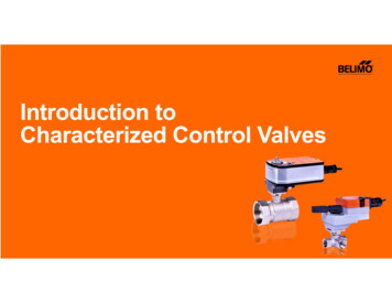
Introduction toCharacterized Control Valves
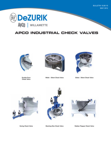
Characterized Control Valve ApplicationsControl valves are suitable for use in a hydronicsystem with variable flow. Air handling units on heating or cooling coils Fan unit heating or cooling coils Unit ventilators VAV box re-heat coils and bypass loops2
Characterized Control Valve (CCV) TechnologyPatented characterizing discthat ensures a true equalpercentage flowcharacteristicEasy InstallationMaintenance-free designBall valve technology0% leakagepreventing ghost energy3
What is Ghost Energy? Leaky control valves increase the call foradditional chilled water or heating water flowscreating waste, which is called Ghost Energy.A 1% leakage creates a 5 to 10% energy loss.4
Characterized Control Valve (CCV) Technology The characterizing disc defines the change in flow as the ball opens to create a flowcharacteristic that can be defined as an equal percentage flow curve.Fully Closed20% Open50% Open80% Open100% Open5
Flow ConfigurationEqual Percentage Flow Characteristic The equal percentage flowcharacteristic of the valve is theinverse of the coil flow characteristicThe combination of these twocharacteristic results in a linearoutput (relationship between ballopening and heat energy) whichallows for a proportional responseCOILCHARACTERISTICCONTROL VALVECHARACTERISTICFlow / Heat 100%0%HEAT OUTPUTSignal / Flow100%6
Characterized Control ValveSelection Criteria Media Type (chilled/hot water or steam)Pattern (2-way, 3-way or 6-way)Valve Size (1/2” to 6”)Piping reduction factor (Fp –if Applicable)Cv Range – Coefficient of FlowControl Type (Open/Close, Floating Point,Modulating)7
Media TypesChilled or Hot WaterSteam8
Valve Configurations 2-WayIsolation & Proportional 3-WayMixing & Diverting/Switching 6-WayDual Temp Systems9
Cv - Piping Reduction Factor (Fp) Correction Factor Values in chart arecorrected Cvratings for indicatedpipe sizeNOTE: Please use the corrected Cv values for the valves listed in the chart when installing them in pipes larger than the line size of the valve. All CCVs not listed do not require pipingreduction factors. The values shown in bold are based on test data. All other values are calculated.10
2-Way Operation2 ports An inlet port (A)and an outlet port (AB)AABValve has a drilled hole through the middle When the hole is in line withthe inlet and outlet ports, flow will occur.To open valve and allow flow Ball is rotated (CCW)—theopening is in line with both A and AB portsTo close valve and stop flow Ball is rotated 90º (CW)—theopening is perpendicular to A and AB ports11
2-Way Valve in Return Piping2 Position or Proportional ControlAABReturnSupplyCoil12
3-Way Mixing3 ports Two inlet ports (A andB) and one outlet port (AB)ABABRotate 90 (CW) to allow flow from B to AB Cv is 70% in the bypassRotate 90 (CCW) to resume flow from A to AB Cv is 100% to thecoil13
3-Way DivertingHave 3 ports One inlet port (AB)and two outlet ports (A and B)ABABRotate 90 (CW) to allow flow from AB to B Cv is 70%Rotate 90 (CCW) to resume flow from AB to A Cv is100%14
Stem Marking and Flow DirectionStem markings show flow throughthe valve (A to AB flow shown)AFlow arrows show mixing orientation2 inlets, A and B, and one outlet, ABABB15
Mixing2 Inputs – 1 OutputAABReturnBSupplyCoil16
Diverting1 Input – 2 Outputs Coil SupplyReturnBCoilAABSupply17
Actuator TypeFail-safe actuators utilize an internal spring that drives the actuator open or closed on loss ofpower. Non fail-safe actuators stay in their current position on loss of power.18
6-Way CCV19
6-Way CCV Application Chilled beam systemsRadiant ceiling panelsRadiant heating/cooling applicationsAnlass, Datum20
6-Way CCVThe 6-way CCV is a rotary valve similar to a CCVbut with 2 control sequences. Sequence operating ranges Sequence¹: 0º to 30º rotation Closed position 30º to 60º Sequence²: 60º to 90º21
6-Way CCV Operation22
6-way CCV OperationOne valve switching andcontrol valveA Cooling controlB Heating controlAB switchingABA modulatingactuator is usedto throttle thevalve over it’srange22
Typical Heating/Cooling ApplicationTerminal Unit (4 pipe), 2-way Valves and 2 Coils ProHEATCOOL Two exchangers (1 coil for heating and 1 for cooling) Con Cost exchanger (cost of 2 coils) Two control sequencesCost of 2 control valves cost of 2 actuators cost of 2 points to control HCCC24
Typical Heating/Cooling ApplicationTerminal Unit (4 pipe), (4) 2-way Valves and 1 CoilsH/C ProOptimize exchanger (1 coil for heating andcooling) Con Costs multiple valves (cost of 4 control valves) Two control sequences (cost of 2 controlsequences and 4 actuators)HCCC25
Typical Heating/Cooling ApplicationTerminal Unit (4 pipe), (1) 6-way Valves and 1 Coils ProH/C Optimize exchanger (1 coil for heating andcooling) Low installation cost 1 valve to installOne control point need to sequence heating andcooling Unit cost of one valveMHCCC26
Further Questions or to OrderUSA33 Turner Road, Danbury, CT 06810Tel. 800-543-9038 Fax. 800-228-82831049 Fortunato Loop, Sparks, NV 89436Canada5845 Kennedy Road, Mississauga, Ontario L4Z 2G3Tel. 866-805-7089 Fax. 905-712-3124Latin America and the CaribbeanTel. 203-791-8396 Fax. 203-791-9139BrazilRua Barbalha, 251, Alto da Lapa, São Paulo - CEP: 05083-020Tel. 55 11 3643-5656 Fax. 55 11 3643 565727
Media Type (chilled/hot water or steam) Pattern (2-way, 3-way or 6-way) Valve Size (1/2" to 6") . Two exchangers (1 coil for heating and 1 for cooling) Con Cost exchanger (cost of 2 coils) Two control sequences HEAT COOL HC CC Cost of 2 control valves
